


You also want an ePaper? Increase the reach of your titles
YUMPU automatically turns print PDFs into web optimized ePapers that Google loves.
<str<strong>on</strong>g>Snap</str<strong>on</strong>g>-<strong>on</strong> EEWB300A Operators Manual<br />
7.0 TIRE MATCHING PROGRAM<br />
The matching program assists the user in determining the<br />
best possible mating of the tire and rim.<br />
The mating of tire and wheel normally allows the least amount<br />
of additi<strong>on</strong>al weight required for balancing and total runout.<br />
The matching program is helpful when:<br />
- Excessive radial runout is noticed.<br />
- The balancer calls for weights in excess of 2 oz. <strong>on</strong> either<br />
plane in the Dynamic mode.<br />
The EEWB300A computer wheel balancer features 2 different<br />
matching programs:<br />
- Static , when the tire has a manufacturers determined directi<strong>on</strong><br />
of rotati<strong>on</strong> and cannot be reversed <strong>on</strong> the rim.<br />
- Dynamic, when the mating may require to rotate and reverse<br />
the tire <strong>on</strong> the rim.<br />
7.1 DYNAMIC TIRE MATCHING<br />
A. Mount the wheel <strong>on</strong> the machine and enter wheel data as<br />
usual. Lower the wheel guard to spin the wheel.<br />
E. Dismount the wheel from balancer.<br />
Deflate tire and rotate the tire 180 degrees <strong>on</strong> the rim (the<br />
mark <strong>on</strong> the tire and the valve shall be at 180 degrees) (Fig.58<br />
#B). Inflate tire to the right pressure respecting all safety<br />
precauti<strong>on</strong>s.<br />
F. Mount the wheel <strong>on</strong>to the balancer with valve at 12 o’clock.<br />
NOTE:<br />
Check that the rim is mounted in the same angular positi<strong>on</strong><br />
with respect to the arbor.<br />
G. Spin the wheel.<br />
Displays show : [Opt] and blink [2— ] [ —2].<br />
H. Move the wheel with the valve at 12 o’clock and press F .<br />
Displays show [Opt] [End] .<br />
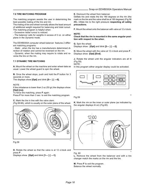
J. Rotate the wheel until the angular indicators are all lit<br />
(Fig.59).<br />
NOTE :<br />
In this program either angular display could be activated.<br />
B. Once the wheel stops, push and hold the F butt<strong>on</strong> for 3<br />
sec<strong>on</strong>ds or more.<br />
The displays show [Opt] and blink [0— ] [ —0].<br />
NOTE :<br />
If the imbalance is lower than 2 oz (50 gr) the displays show:<br />
[Opt] [no].<br />
To force tire matching, press F again.<br />
Press F for more than 3 sec. to exit the matching program.<br />
C. Mark the tire in line with the valve stem.<br />
(Fig.58 #A), which is usually <strong>on</strong> the outer plane of the wheel.<br />
Fig.59<br />
K. Mark the rim <strong>on</strong> the inner or outer plane (as indicated by<br />
the angular displays lit <strong>on</strong>) (Fig.60).<br />
168<br />
Fig.58<br />
61<br />
D. Rotate the wheel so that the valve is at 12 o’clock and<br />
press F .<br />
Displays show [Opt] and blink [1— ] [ —1].<br />
Fig. 60<br />
L. Remove the wheel from the balancer and with a tire<br />
changer match the marks <strong>on</strong> the rim and the tire.<br />
63<br />
M. Press F to exit the program.<br />
Balance the wheel normally.<br />
Page 16


