50 MW OTEC Plantship Design - Hawaii National Marine ...
50 MW OTEC Plantship Design - Hawaii National Marine ...
50 MW OTEC Plantship Design - Hawaii National Marine ...

Create successful ePaper yourself
Turn your PDF publications into a flip-book with our unique Google optimized e-Paper software.
14 OTC 20957<br />
The conceptual position control system consists of two subsystems: a single point moor to maintain position, within a given<br />
watch circle, during <strong>OTEC</strong> operations and up to the site departure condition; and, four propulsion and position control<br />
thrusters to assist in directional positioning (weather vaning) during operations and to provide the propulsive power required<br />
to depart the site. The single point mooring subsystem is available from several manufacturers. For the CC-<strong>OTEC</strong> system<br />
four propulsion thrusters are rated at ≈ 2,000 kW each and would be used minimally during operations. The actual schedule<br />
for thruster usage would be developed during the final design phase.<br />
The single-point mooring system includes a power cable swivel, and a water hose swivel. The power cable and water hose<br />
are linked to the <strong>OTEC</strong> plant at their respective swivels on the turntable. This system provides a minimal-thruster-powerconsumption<br />
means of holding the <strong>OTEC</strong> platform in position. Auxiliary power diesel generators would be available to<br />
operate the thrusters during transit and departure, as well as in situ when <strong>OTEC</strong> power is not available.<br />
<strong>OTEC</strong> Seawater Components<br />
The <strong>OTEC</strong> seawater system consists of the pipes and pumps required to supply warm and cold seawater streams to the <strong>OTEC</strong><br />
heat exchangers and allow for the return of effluents to the ocean. The concept considered for the cold water pipe (CWP) is<br />
an 8.7 m i.d. FRP sandwich pipe suspended from the <strong>OTEC</strong> platform to a depth of 1,000 m. Warm seawater will be drawn in<br />
through two 10 m i.d. pipes from a depth of about 20 m. The mixed effluent will be returned through two 12.3 m i.d. FRP<br />
pipes at a depth of 60 m. This depth has been selected to minimize the environmental impact.<br />
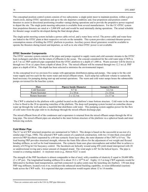
At the conceptual level we envision five sumps with appropriate distribution piping and pumps. One sump is for the cold<br />
water supply and two each for the warm water and mixed effluent return. Each sump has sufficient volume to sustain the<br />
head necessary for pumping during start-up and normal operations. The warm and cold water sumps house the submersible<br />
pumps envisioned for the baseline system.<br />
Flow Pipe(s) Inside Diameter Sump(s) Diameter<br />
Cold Seawater 8.7 m 12.3 m<br />
Warm Seawater 2 x 10 m 2 x 14 m<br />
Return Seawater 2 x 12.3 m 2 x 17 m<br />
The CWP is attached to the platform with a gimbal located on the platform’s inner bottom structure. Cold water in the sump<br />
is free to flood to the 20 m operating waterline of the platform. The deep-well pumping system located on centerline draws<br />
water up through the well and into a manifold that distributes cold water. This pumping system supplies power for the flow<br />
of cold water from the pipe inlet to its discharge through the mixed effluent discharge pipe.<br />
The mixed effluent from all of the condensers and evaporators is returned from the mixed effluent sumps through the 40 m<br />
long pipe. The mixed effluent pipes are attached to the inner bottom structure of the platform via a spherical heads and inner<br />
bottom ring sockets.<br />
Cold Water Pipe<br />
The 8.7 m id CWP structural properties are summarized in Table 6. This design is based on the successful at-sea test of a<br />
similar pipe (Vega, 1988). The selected CWP walls consist of a sandwich construction, with two 14 mm thick cross-plied<br />
unwoven FRP facesheets separated by a 60 mm syntactic foam layer (thus, the outer diameter of the CWP is 8.9 m). The<br />
load bearing FRP provides structural strength, whereas the foam filler allows for the adjustment of wet weight and flexural<br />
bending stiffness, as well as for load transmission. The syntactic foam uses glass microspheres and milled fiber to achieve a<br />
density of 670 kg/m3 for buoyancy control. The facesheets are helically wound using 4<strong>50</strong> yield strand interspersed with 20<br />
oz unidirectional roving and a minor amount of chopped strand. The wind angle is 60° for the helical layers. The pipe is<br />
wound in a rotating mandrel. A vinylester resin (e.g., Hetron 922) 2 is used.<br />
The strength of the FRP facesheets is almost comparable to that of steel, with a modulus of elasticity E equal to 20,600 MPa<br />
(3 x 10 6 psi). The longitudinal bending stiffness EI is about 19.2 x 10 10 N-m 2 . Eighty 12.5 m long CWP segments would be<br />
fabricated to facilitate land transportation, and butt-connected via splice joints near the launching site (harbor). 1<strong>50</strong> mm deep<br />
FRP ring stiffeners, located every 6 m, would provide enhanced lateral buckling capability, to resist differential (suction)<br />
loads across the CWP walls. It is expected that pipe construction would require about 12 to 14 months.<br />
2 These are common units used in the USA by FRP pipe fabricators.