50 MW OTEC Plantship Design - Hawaii National Marine ...
50 MW OTEC Plantship Design - Hawaii National Marine ...
50 MW OTEC Plantship Design - Hawaii National Marine ...

Create successful ePaper yourself
Turn your PDF publications into a flip-book with our unique Google optimized e-Paper software.
OTC 20957 15<br />
Parameter<br />
Value<br />
Inside Diameter<br />
8.7 m<br />
Laminate (facesheet) thickness<br />
14 mm<br />
Core (syntactic foam) thickness<br />
60 mm<br />
Laminate Density 1760 kg/m 3<br />
Outside Diameter<br />
8.9 m<br />
Core Density 670 kg/m 3<br />
Dry (air) Weight<br />
2,460 kg/m<br />
Wet (submerged) Weight<br />
3 kg/m<br />
Flexural Rigidity, EI 19.2 x 10 10 N-m 2 (46.4 x 10 10 lb-f 2<br />
Laminate Modulus of Elasticity<br />
20,680 MPa (3 x 10 6 psi)<br />
Core Modulus of Elasticity<br />
2,370 MPa (0.344 x 10 6 psi)<br />
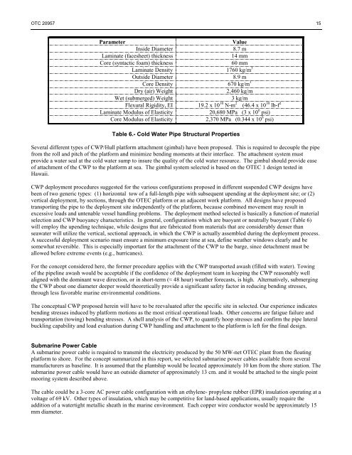
Table 6.- Cold Water Pipe Structural Properties<br />
Several different types of CWP/Hull platform attachment (gimbal) have been proposed. This is required to decouple the pipe<br />
from the roll and pitch of the platform and minimize bending moments at their interface. The attachment system must<br />
provide a water seal at the cold water sump to insure the quality of the cold water resource. The gimbal should provide ease<br />
of attachment of the CWP to the platform at sea. The gimbal system selected is based on the <strong>OTEC</strong> 1 design tested in<br />
<strong>Hawaii</strong>.<br />
CWP deployment procedures suggested for the various configurations proposed in different suspended CWP designs have<br />
been of two generic types: (1) horizontal tow of a full-length pipe with subsequent upending at the deployment site; or (2)<br />
vertical deployment, by sections, through the <strong>OTEC</strong> platform or an adjacent work platform. All designs have proposed<br />
transporting the pipe to the deployment site independently of the platform, because combined movement may result in<br />
excessive loads and untenable vessel handling problems. The deployment method selected is basically a function of material<br />
selection and CWP buoyancy characteristics. In general, configurations which are buoyant or neutrally buoyant (Table 6)<br />
will employ the upending technique, while designs that are fabricated from materials that are considerably denser than<br />
seawater will utilize the vertical, sectional approach, in which the CWP is actually assembled during the deployment process.<br />
A successful deployment scenario must ensure a minimum exposure time at sea, define weather windows clearly and be<br />
somewhat reversible. This is especially important for the attachment of the CWP to the barge, since detachment must be<br />
allowed before extreme events (e.g., hurricanes).<br />
For the concept considered here, the former procedure applies with the CWP transported awash (filled with water). Towing<br />
of the pipeline awash would be acceptable if the confidence of the deployment team in keeping the CWP reasonably well<br />
aligned with the dominant wave direction, or in short-term (≈ 48 hour) weather forecasts, is high. Alternatively, submerging<br />
the CWP about one diameter deeper would theoretically provide a significant safety factor in reducing bending stresses,<br />
through less favorable marine environmental conditions.<br />
The conceptual CWP proposed herein will have to be reevaluated after the specific site in selected. Our experience indicates<br />
bending stresses induced by platform motions as the most critical operational loads. Other concerns are fatigue failure and<br />
transportation (towing) bending stresses. A shell analysis of the CWP, to quantify hoop stresses and confirm the pipe lateral<br />
buckling capability and load evaluation during CWP handling and attachment to the platform is left for the final design.<br />
Submarine Power Cable<br />
A submarine power cable is required to transmit the electricity produced by the <strong>50</strong> <strong>MW</strong>-net <strong>OTEC</strong> plant from the floating<br />
platform to shore. For the concept summarized in this report, we selected submarine power cables available from several<br />
manufacturers as baseline. It is assumed that the plantship would be located approximately 10 km from the shore station. The<br />
submarine power cable would have an outside diameter of approximately 13 cm. and it would be attached to the single point<br />
mooring system described above.<br />
The cable could be a 3-core AC power cable configuration with an ethylene- propylene rubber (EPR) insulation operating at a<br />
voltage of 69 kV. Other types of insulation, which may be competitive for land-based applications, usually require the<br />
addition of a watertight metallic sheath in the marine environment. Each copper wire conductor would be approximately 15<br />
mm diameter.