User Manual - IBP Medical
User Manual - IBP Medical
User Manual - IBP Medical

Create successful ePaper yourself
Turn your PDF publications into a flip-book with our unique Google optimized e-Paper software.
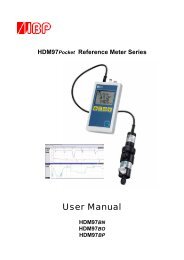
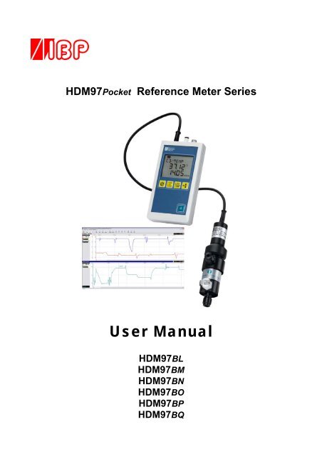
HDM97Pocket Reference Meter Series<br />
<strong>User</strong> <strong>Manual</strong><br />
HDM97BL<br />
HDM97BM<br />
HDM97BN<br />
HDM97BO<br />
HDM97BP<br />
HDM97BQ
Preface<br />
The information contained in this is subject to change without notice. <strong>IBP</strong> <strong>Medical</strong> GmbH, its distributors and subsidiaries take no<br />
responsibility for any errors or omissions in this document. The contained software is being delivered on the basis of a general licence<br />
contract or in single license. Use or reproduction of the software is allowed only in agreement with the contractual arrangements.<br />
Whoever transfers this software and/or this manual on magnetic tape, diskette or any other media, except for the purpose of own use,<br />
without written authorization of the <strong>IBP</strong> <strong>Medical</strong> GmbH, is liable to prosecution.<br />
Copyright (C) 2009 <strong>IBP</strong> <strong>Medical</strong> GmbH.<br />
All rights reserved<br />
All brand names mentioned in this document are property of their respective owners.<br />
Publishers: <strong>IBP</strong> <strong>Medical</strong> GmbH <strong>IBP</strong> <strong>Medical</strong> Inc<br />
Ikarusallee 15<br />
4113 W. St. Charles Ave.<br />
D 30179 Hannover Phoenix, AZ 85041<br />
Germany<br />
USA<br />
Phone: +49 511 651647 1-865-686-8650<br />
Fax: +49 511 652284 1-866-243-0187<br />
Internet: http://www.ibpmedical.com http://www.ibpmedical.com<br />
E-Mail: support@ibpmedical.com america@ibpmedical.com<br />
<strong>Manual</strong> authors:<br />
Dipl. Ing. Werner Pfingstmann<br />
Holger Kleinert<br />
Document Number<br />
DHDM97.0220.01<br />
Revision history Rev. 0. 29.05.2008<br />
Rev. 1. 18.03.2009 Update Hard- und Software release 2.0<br />
Rev. 2. 01.10.2009 Update Flow sensor<br />
Rev. 3. 04.11.2009 Update Flowsensor Cleaning<br />
This manual is only valid for the software revisions listed below:<br />
HDM97BL V 2.00 ...2.19<br />
HDM97BM V 2.00 ...2.19<br />
HDM97BN V 2.00 ...2.19<br />
HDM97BO V 2.00 ...2.19<br />
HDM97BP V 2.00 ...2.19<br />
HDM97BO V 2.00 ...2.19<br />
HDM97BQ V 2.00 ...2.19<br />
<strong>IBP</strong>View V 2.00<br />
0482
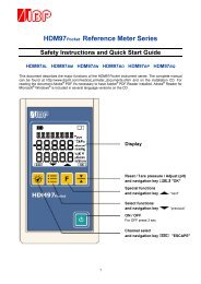
SAFETY INSTRUCTIONS<br />
For your and your patients safety read and consider the safety instructions below carefully<br />
• Read the entire manual carefully before using the HDM97Pocket .<br />
• Keep the instrument away from unauthorised persons.<br />
• Only use the HDM97Pocket as reference instrument to measure Conductivity, Temperature,<br />
Pressure, Flow and pH depending to it's equipped features.<br />
• Never use the HDM97Pocket as a replacement of sensors of a medical device.<br />
• Do not use the HDM97Pocket in conjunction with a medical device during a treatment.<br />
• Only use the instrument in a dry environment and do not touch it with wet hands.<br />
• Make sure that no liquids intrude inside the instrument or it's inlets / outlets.<br />
• Always use a clean protection filter for the pressure transducer inlet.<br />
• Prevent every mechanical overstraining of electrical wires. Never buckle or pull the cable of the<br />
conductivity probe.<br />
• If the acquired values seem to be not believable, make sure that the HDM97Pocket is not defective<br />
• Prevent electrostatic discharge on the connectors. This can lead to substantial damage of the<br />
instrument. Make sure to be completely discharged before touching the connectors or cables<br />
connected to the instrument.<br />
• Adjust the meter only, if you are familiar with the consequences of the adjustment. Consider the<br />
hints for reference solutions in the user manual.<br />
• Potentials above 42V against earth ground are dangerous. This potentials can lead to electrical<br />
shock and therefore to health hazards. Make sure that none of the connectors has higher voltage<br />
than mentioned before.<br />
• The direct connection of earth potential to any connector of the instrument is not applicable for<br />
safety purposes and may substantially damage the instrument. Make sure that the medical device<br />
itself is properly connected to earth ground according to its instruction manual.<br />
• Make sure that the instrument never heats over 60°C / 140°F. Prevent direct sunlight.<br />
• Never sterilize the instrument using an autoclave. Danger of explosion of the battery!<br />
• Never throw the meter into a fire. Danger of explosion of the battery!<br />
• Never open the meter. There are no parts inside you can repair.<br />
• Never try to replace or repair the internal battery. Handled in the wrong way these part is<br />
dangerous. Extreme risk of fire and explosion!
1<br />
Table of content<br />
Introduction ..................................................................................................................................... 2<br />
Application ...................................................................................................................................... 2<br />
EC DECLARATION OF CONFORMITY ........................................................................................... 3<br />
Delivery Content ............................................................................................................................. 4<br />
Warranty .......................................................................................................................................... 5<br />
Product Overview ........................................................................................................................... 6<br />
The versions at a glance ............................................................................................................................... 6<br />
Measuring Channels ..................................................................................................................................... 7<br />
Charging the battery ...................................................................................................................................... 8<br />
Performing measurements while the battery is being charged ..................................................................... 8<br />
Flow-through adapter for conductivity and temperature measurement ........................................................ 8<br />
Keypad .......................................................................................................................................................... 9<br />
Switching on the instrument ........................................................................................................................ 10<br />
Display test during start up .......................................................................................................................... 10<br />
Power saving function ................................................................................................................................. 10<br />
Displaying battery charge progress and finish ............................................................................................ 10<br />
Battery gauge display during operation ....................................................................................................... 11<br />
Battery aging ............................................................................................................................................... 11<br />
Battery replacement – ONLY BY MANUFACTURER ................................................................................. 11<br />
Value adjustment ......................................................................................................................................... 14<br />
Measuring ...................................................................................................................................... 15<br />
Conductivity and temperature measurement .............................................................................................. 15<br />
Fundamentals of temperature compensation .............................................................................................. 15<br />
Appliance of temperature coefficients ......................................................................................................... 15<br />
Temperature compensation in dialysis ........................................................................................................ 17<br />
Temperature measurement ......................................................................................................................... 19<br />
Pressure measurement ............................................................................................................................... 19<br />
Pressure drop measurement ....................................................................................................................... 20<br />
pH measurement ......................................................................................................................................... 20<br />
Fundamental information about pH measurement ...................................................................................... 20<br />
Stopwatch (TIMER) ....................................................................................................................... 21<br />
Flow measurement ..................................................................................................................................... 21<br />
Attenuation of reading .................................................................................................................. 22<br />
Adjustment and Calibration ......................................................................................................... 23<br />
Adjustment and Calibration ......................................................................................................... 23<br />
Precautions ................................................................................................................................................. 23<br />
Definitions .................................................................................................................................................... 23<br />
General ........................................................................................................................................................ 23<br />
Handling of Reference Solutions ................................................................................................................. 24<br />
Adjusting the HDM97Pocket ....................................................................................................................... 24<br />
Maintenance of HDM97Pocket ..................................................................................................... 27<br />
Troubleshooting ............................................................................................................................ 30<br />
Technical data ............................................................................................................................... 31<br />
PC Interface ................................................................................................................................... 33<br />
USB Interface .............................................................................................................................................. 33<br />
Interface parameters for serial COM port emulation ................................................................................... 33<br />
Driver installation, example for Microsoft ® Windows ® XP Service Pack 2 ......................................................... 34<br />
Example ....................................................................................................................................................... 36<br />
<strong>IBP</strong>View .......................................................................................................................................... 37<br />
What is <strong>IBP</strong>View .......................................................................................................................................... 37<br />
Installation ................................................................................................................................................... 38<br />
Quickstart .................................................................................................................................................... 38<br />
Disconnect USB .......................................................................................................................................... 38<br />
Main Window ............................................................................................................................................... 38<br />
Selecting hardware ...................................................................................................................................... 39<br />
Assigning graphs to hardware channels ..................................................................................................... 40<br />
List of channels ........................................................................................................................................... 41
Introduction 2<br />
Introduction<br />
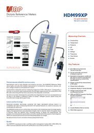
The HDM97Pocket meter series are reference instrument designed for the calibration of medical devices such<br />
as hemodialysis machines. Please read this entire manual carefully before the first use of the instrument.<br />
Application<br />
Depending on the version the HDM97Pocket may be equipped with up to 5 acquisition channels:<br />
Channel HDM97BL HDM97BM HDM97BN HDM97BO HDM97BP HDM97BQ<br />
Conductivity <br />
Temperature <br />
Timer <br />
Pressure <br />
pH<br />
<br />
Flow <br />
The instrument was designed to be used as a dialysis machine maintenance instrument, but can also be used<br />
as laboratory measuring instrument as well as instrument for environmental purposes.<br />
This instrument displays measuring values numeric. Graphical displays are available through a PC or<br />
Notebook using the optional Software <strong>IBP</strong>View.<br />
Using the USB communication interface it is possible to obtain measuring values regardless of the<br />
instrument display's content. These values can be displayed in any way or stored for further processing.
3 EC Declaration of Conformity<br />
EC DECLARATION OF CONFORMITY<br />
according to the Council Directive 93/42/EEC concerning medical devices<br />
Manufacturer<br />
<strong>IBP</strong> <strong>Medical</strong> GmbH<br />
Ikarusallee 15<br />
30179 Hannover<br />
declare under our sole responsibility that the<br />
following products:<br />
Dialysis Reference Meter<br />
Version HDM97BL<br />
HDM97BM<br />
HDM97BN<br />
HDM97BO<br />
HDM97BP<br />
HDM97BQ<br />
HDM99XP<br />
Product Code: 31.0XXX.XX<br />
X = Depending on Version<br />
meet the provisions of the Council Directive<br />
93/42/EEC concerning medical devices<br />
which apply to them.<br />
Product Classification<br />
II B<br />
Notified Body<br />
Identification Number<br />
Medcert GmbH<br />
Vorsetzen 35<br />
20459 Hamburg<br />
0482<br />
Hannover 18.04.09<br />
Responsible:<br />
Dipl. Ing. Werner Pfingstmann
Delivery 4<br />
Delivery Content<br />
Pos. Description Version Standard Option<br />
1 HDM97Pocket meter BL, BM, BN, BO, BP, BQ <br />
2 Conductivity/Temperature Probe BN, BO, BP, BQ <br />
3 Dialyser Line Adapter BN, BO, BP, BQ <br />
4 Hose for pressure measurement BM, BO, BP, BQ <br />
5 14,00 mS/cm Conductivity Reference Solution BN, BO, BP, BQ <br />
6 Battery charger with wall plug adapters All <br />
7 USB interface cable All <br />
8<br />
CD - HDM97Pocket with USB drivers, Software<br />
and <strong>User</strong> <strong>Manual</strong><br />
All<br />
<br />
9 Safety instructions and quick start guide All <br />
10 Flow Sensor BL <br />
11 Flow Sensor BQ <br />
12 pH Probe with buffer solution pH6, 7 and 8 BP <br />
13 Carrying case All <br />
14 Holder Infusion pole All <br />
15 CD - <strong>IBP</strong>View Data Acquisition Software All
5 Warranty<br />
Warranty<br />
<strong>IBP</strong> <strong>Medical</strong> GmbH warrants that it will repair or replace, at its option, any defective or malfunctioning part<br />
without charge for the terms listed below. Parts used for repair or replacement are warranted for the<br />
remaining warranty period only.<br />
The user must deliver, at its own expense, the product to <strong>IBP</strong> <strong>Medical</strong> GmbH.<br />
Parts<br />
HDM97Pocket<br />
pH-Probe<br />
Warranty –Period*<br />
24 Month<br />
6 Month<br />
* from date of delivery note<br />
The warranty does not cover:<br />
• Disposable parts as battery or pH electrode<br />
• Annually calibration<br />
• Cell cleaning<br />
• Defects caused by:<br />
1. Modification, alteration, repair or service of the product by anyone<br />
other than <strong>IBP</strong> <strong>Medical</strong> or an authorized service center<br />
2. Misuse due to negligence or accident<br />
3. Operation or maintenance of the product in a manner contrary<br />
to <strong>IBP</strong> instructions<br />
Any express warranty not provided herein, and any remedy for breach of contract that but for this provision<br />
might arise by implication or operation of law, is hereby excluded and disclaimed. The implied warranties of<br />
merchantability and of fitness for any particular purpose are expressly limited to the terms mentioned above.<br />
Some states do not allow limitations on the duration of an implied warranty, so the above limitation may not<br />
apply to you.<br />
Under no circumstances shall <strong>IBP</strong> <strong>Medical</strong> GmbH be liable to the original purchaser or to any other person<br />
for any special or consequential damages, whether arising out of breach of warranty, breach of contract, or<br />
otherwise. Some states do not allow the exclusion or limitation of special or consequential damages, so the<br />
above exclusion or limitation may not apply to you.<br />
This warranty gives you specific legal rights, and you may also have other rights that vary from state to state.<br />
For further warranty information, contact <strong>IBP</strong> <strong>Medical</strong> GmbH.
General 6<br />
Product Overview<br />
HDM97BL<br />
HDM97BM<br />
Flow<br />
Pressure<br />
HDM97BN<br />
HDM97BO<br />
HDM97BP<br />
Conductivity<br />
Temperature<br />
HDM97BQ<br />
Pressure<br />
Conductivity<br />
Temperature<br />
pH Pressure Conductivity<br />
Temperature<br />
Flow Pressure Conductivity<br />
Temperature<br />
The versions at a glance<br />
HDM97BL<br />
This version is suited for usage with a HDU FLOW Sensor and is also equipped with a timer function<br />
HDM97BM<br />
This version is equipped with a high resolution pressure transducer, has a pressure drop measurement<br />
function and a timer function. The high precision pressure transducer is not waterproof!<br />
HDM97BN<br />
This version is equipped with the conductivity / temperature probe only. It also has the timer function built<br />
in.<br />
HDM97BO<br />
This version is equipped with the conductivity / temperature probe and a standard precision water proof<br />
pressure transducer. It also has the pressure drop measurement and the timer function built in.<br />
HDM97BP<br />
This version is equipped with the conductivity / temperature probe and a standard precision water proof<br />
pressure transducer. It also has the pressure drop measurement and the timer function built in. It can also<br />
measure pH with standard pH sensors.<br />
HDM97BQ<br />
This version is equipped with the conductivity / temperature probe and a standard precision water proof<br />
pressure transducer. The high precision pressure transducer is available as “Option H” for this version. This<br />
high precision pressure transducer is not waterproof. The meter can also measure flow by using the HDU<br />
FLOW probe. It also has the pressure drop measurement and the timer function built in.
7 General<br />
Measuring Channels<br />
Only use accessories provided with the HDM97Pocket . Use of other devices may damage the instrument and<br />
will void the warranty.<br />
Conductivity/Temperature Probe<br />
The conductivity/temperature transducer is a quadropole design for greater accuracy and longevity than other<br />
designs.<br />
Standard precision pressure transducer<br />
This pressure transducer is watertight. However it is recommended to keep fluids away from the sensor<br />
because residues like salt can falsify measurement results. In this case the sensor needs to be flushed with<br />
deionized water.<br />
High precision pressure transducer<br />
To avoid damage or inaccurate measurement, ensure that no fluids enter the instrument. We recommend the<br />
use of a Transducer Protector for this purpose. Never flush the sensor.<br />
Pressure drop measurement<br />
This is not a real channel, it is a function for measuring pressure loss in systems for s specified time.<br />
Timer<br />
This is not a real channel, it is a function to help performing anything where time is a crucial element.<br />
pH<br />
The input connector is designed exclusively for pH electrodes. It is optimized for glass electrode single-rod<br />
measuring cells with a slope of ∆E of 59mV at 20°C. Its absolute maximum allowable input voltage span<br />
extends from -3 Volts to +3 Volts with respect to BNC Shield. Applying any voltage beyond these<br />
boundaries will possibly destroy the instrument.<br />
Flow<br />
This connection is designed to be used with the HDU FLOW probe only. Do not connect any other devices<br />
to this port even when the connector may fit.
General 8<br />
Charging the battery<br />
The HDM97Pocket is internally equipped with a high performance Lithium-Ion-Polymer battery. It can be<br />
charged using the external power supply, a PC or a laptop which is connected via the USB cable to the<br />
instrument. The battery of the HDM97Pocket can only be charged from USB ports which are capable of<br />
delivering 500 mA of current.<br />
This is appropriate to most connectors of laptops or PC's. Connecting the meter to a<br />
passive (e.g. not externally powered) USB hub, the battery can not be charged and<br />
the communication may not work well. During the charging process the battery<br />
symbol in the display is animated.<br />
Performing measurements while the battery is being charged<br />
The HDM97Pocket can be used for measuring while the battery is being charged. To maintain the dialysis<br />
machine and the patient's safety the USB part is isolated to the appliance part of the meter withstanding a<br />
voltage of 4000 Volts AC or 6000 Volts DC for at least one minute according to EN60601-1. The appliance<br />
part consists of the conductivity, temperature, pressure and pH channel and its connectors, depending on the<br />
version.<br />
ATTENTION: The USB connector is not part of the appliance part.<br />
Flow-through adapter for conductivity and temperature measurement<br />
Screw cap<br />
<br />
The adapter is suitable for measuring pressure, temperature and conductivity<br />
in flow-though mode. With immersion usage of the probe it is suitable for<br />
measuring temperature and conductivity concurrently. The preferred<br />
orientation of the adapter is vertical. The axial connector must point down<br />
(see picture). In flow-through mode the axial connector is to be used as inlet<br />
meanwhile the side connector is to be used as outlet. The connection to the<br />
pressure transducer inside the HDM97Pocket is accomplished by the lateral<br />
connection above the inlet. Before measurement it is necessary to shake the<br />
adapter slightly, so that air bubbles trapped inside can pass off through the<br />
outlet.<br />
For immersion usage the probe must be unscrewed from the flow-through<br />
adapter. To accomplish that do not turn the upper shank, the probe may be<br />
damaged. Only turn the nut as shown in the picture left.<br />
Dialysate<br />
pressure<br />
outlet<br />
Never touch the electrode surfaces with your<br />
fingers or other objects.<br />
<br />
Do not buckle the cable of the probe.<br />
The minimum allowed bending radius is<br />
3 cm e.g. 1¼ inches.
9 General<br />
Keypad<br />
Main functions<br />
The keypads main functions of the HDM97Pocket are listed below:<br />
Key<br />
for switching the instrument on and off<br />
Key<br />
for selecting the channel CD/TP ; TP ; PRESSURE ; pH<br />
Key<br />
for selecting the unit to display.<br />
Key<br />
leads to channel dependent special functions<br />
Key<br />
to tare the pressure transducer<br />
The keypad layout is shown in the left picture.<br />
The keys , and have different sub functions depending on the channel<br />
currently displayed. These sub functions are explained in chapter "Measuring"<br />
Additional functions<br />
The yellow keys below the display can be used to<br />
set values and navigate through menu options or<br />
setting. These functions become available when<br />
the symbols shown in the right picture appear at the<br />
bottom of the display.<br />
Cancels the current setting or selection and returns to measuring mode.<br />
Decreases a value or selects the previous option in a menu or a setting.<br />
Increases a value or selects the next option in a menu or a setting.<br />
Applies a value or a selects an option in a menu or a setting.
General 10<br />
Switching on the instrument<br />
The instrument is switched on and off by pressing the<br />
key.<br />
Display test during start up<br />
Immediately after switching on the instrument the display shows all<br />
possible segments dark for two seconds. Compare the display with<br />
the picture on the right side. Do not use the instrument further if you<br />
discover any missing segment, because wrong values could be<br />
displayed which may lead to misreading.<br />
The content of the display must be shown exactly like this picture<br />
right from this text.<br />
Power saving function<br />
The HDM97Pocket switches off automatically if the battery is empty. If enabled, it also switches off after a<br />
specified time if one of the conditions listed below becomes true for the specified time period.<br />
• In pressure mode: The value remains 0 for the specified time period<br />
• In conductivity mode: The conductivity is 0 µs/cm for the specified time period<br />
• In pH mode: The pH probe is not connected for the specified time period<br />
The HDM97Pocket does not switch off when one of the conditions below are met<br />
• A computer is connected to the meter<br />
• The TIMER / stopwatch is running, regardless if displayed or hidden.<br />
Displaying battery charge progress and finish<br />
If the battery is being charged the symbol at the left top corner in the display is animated in 4 steps. There is<br />
a delay of one second displaying each step. After the last step has been displayed the animation starts from<br />
again like illustrated in the picture below.<br />
<br />
<br />
<br />
<br />
After the battery has been charged up to its maximum capacity, the inner 3 columns of the battery symbol<br />
start to blink in a one second period as shown is the illustration below.
11 General<br />
Battery gauge display during operation<br />
If nothing is connected to the USB port during operation the internal battery is used to supply power to the<br />
instrument. The battery symbol in the left top corner of the display shows the remaining capacity of the<br />
internal battery. The combinations have the meanings listed below:<br />
The battery is 100% full.<br />
The battery has approx. 2/3 of its capacity left.<br />
The battery has approx. 1/3 of its capacity left.<br />
The battery is empty, approx 10% is left.<br />
If this symbol starts flashing the battery is totally empty and the meter will switch<br />
off shortly.<br />
Battery aging<br />
The battery technology of the HDM97Pocket is based on Lithium-Ion-Polymer technology. This technology<br />
has many advantages compared with Nickel-Metal-Hydride technology which are lower weight, smaller size,<br />
longer life, no memory effect and higher efficiency. However, after a couple of years (5 years estimated) the<br />
battery's capacity will start decreasing.<br />
Battery replacement – ONLY BY MANUFACTURER<br />
Do not try to replace the battery by yourself. The battery is mounted directly onto the main PCB inside the<br />
HDM97Pocket, and the main PCB itself contains the battery protection circuit. If the battery is not handled in<br />
the right way, there is extremely danger of fire and explosion. Therefore, this battery can only be replaced<br />
from <strong>IBP</strong> personnel who have run through a special training in handling Lithium-Ion batteries.
Base Installation 12<br />
Basic settings<br />
To invoke the installation menu please follow the steps below:<br />
1. Switch off the meter using the key.<br />
2. Switch it on again using the same key.<br />
3. Immediately press the key once during the display test.<br />
4. After this procedure the instruments starts the basic settings dialog instead of entering any measurement<br />
functions.<br />
5. In the basic settings dialog the user is able to adjust a variety of settings.<br />
These are:<br />
Parameter Meter Versions Description<br />
AUTO-OFF All Set the delay time fort he auto power off function or disables it.<br />
BEEP All enables / disables the keypad acknowledge beep<br />
CAL-RES<br />
All<br />
LANGUAGE All<br />
Overwrites the user calibration dataset with the device initial<br />
calibration dataset.<br />
Adjusts the display language.<br />
PHT BM,BO,BP,BQ Target time adjustment for pressure holt test (PHT)<br />
TIMER All enables / disables the stopwatch function<br />
Flow BL, BQ enables / disables the Flow channel<br />
pH BP enables / disables the pH channel<br />
TEMP BN, BO, BP, BQ enables / disables the sole readout of the temperature channel<br />
→<br />
AUTO-OFF<br />
→ OFF → disables function<br />
→ 30 MIN → 30 minutes delay<br />
→ 60 MIN → 60 minutes delay<br />
→ 90 MIN → 90 minutes delay<br />
Then<br />
or<br />
to apply and save this setting,<br />
to discard this setting.<br />
→<br />
BEEP<br />
→ ON → keypad beep enabled<br />
→ OFF → keypad beep disabled<br />
Then<br />
or<br />
to apply and save this setting,<br />
to discard this setting.
13 Base Installation<br />
→<br />
CAL-RES<br />
→<br />
Press 5 seconds until the counter in the display reaches zero.<br />
Then a calibration dataset reset will be performed. This takes<br />
a couple of seconds. The instrument performes a restart afterwards.<br />
→<br />
LANGUAGE<br />
→ DEUTSCH → german language<br />
→ ENGLISH → english language<br />
Then<br />
or<br />
to apply save this setting,<br />
to discard this setting.<br />
→<br />
TIMER<br />
→ ON → stopwatch function enabled<br />
→ OFF → stopwatch function disabled<br />
Then<br />
or<br />
to apply and save this setting,<br />
to discard this setting.<br />
→<br />
PHT (pressure hold test)<br />
→<br />
→<br />
increases the value<br />
lowers the value<br />
Then<br />
or<br />
to apply and save this setting,<br />
to discard this setting.<br />
→<br />
PH<br />
→ ON → pH enabled<br />
→ OFF → pH disabled<br />
Then<br />
or<br />
to apply save this setting,<br />
to discard this setting.<br />
→ FLOW only available with version BQ<br />
→ ON → FLOW enabled<br />
→ OFF → FLOW disabled<br />
Then<br />
or<br />
disabled<br />
to apply save this setting,<br />
to discard this setting.<br />
→<br />
TEMP<br />
→ ON → sole readout of temperature enabled<br />
→ OFF → sole readout of temperature<br />
disabled<br />
Then<br />
or<br />
to apply and save this setting,<br />
to discard this setting.
Base Installation 14<br />
→<br />
→<br />
EXIT<br />
SAVE<br />
A save dialog will appear, if changes have been made.<br />
→ YES to apply and save all settings by exiting<br />
→ NO to discard all settings by exiting<br />
Then<br />
or<br />
to exit the basic settings dialog,<br />
to return to the basic settings dialog.<br />
Value adjustment<br />
The adjustment of values is done via the navigation keys and . By pressing and holding down<br />
one of these keys the last (right) digit of the value will be incremented or decremented depending on the key.<br />
If this digit reaches the boundary it remains 0 and the next digit will begin to change. If the key is being<br />
released and pressed again the procedure will start again beginning with the last digit.<br />
Example showing a value, which has an allowable range from 0.00 to 7.50:<br />
Display: 0.00 ; navigationkey is hold down:<br />
Order of value incements (every change follows with a delay of 0.3 seconds):<br />
0.01→0.02→0.03→0.04→0.05→0.06→0.07→0.08→0.09<br />
(carry-over)<br />
0.10→0.20→0.30→0.40→0.50→0.60→0.70→0.80→0.90<br />
(carry-over)<br />
1.00→2.00→3.00→4.00→5.00→6.00→7.00→7.50<br />
(Max value reached)<br />
If the value will exceed the range limits (in this case from 7.00 to 8.00) the value will be truncated to the<br />
maximum allowed value, 7.50 in this particular example. The Symbol will become blank and the<br />
meter does not react on the corresponding navigation key. The values can only be changed down to 0.00<br />
using the other key.
15 Adjustment and Calibration<br />
Measuring<br />
By pressing the key the user can select between all available channels of the HDM97Pocket .<br />
These channels are<br />
• Conductivity and temperature Display "CD/TEMP" only Version BN, BO, BP, BQ<br />
• Temperature Display "TEMP" only Version BN, BO, BP, BQ if enabled<br />
• Pressure Display "PRES" only Version DA, BO, BP, BQ<br />
• pH Display "PH" only HDM97BP, if enabled<br />
• Flow Display "FLOW" only HDM97BQ, if enabled<br />
• Timer Display "Time" if enabled<br />
Conductivity and temperature measurement<br />
In this mode the display shows "CD/TEMP" in the upper line, the temperature value in the middle line and<br />
the conductivity value in the bottom line.<br />
By pressing the key<br />
the user can choose the temperature coefficient.<br />
Fundamentals of temperature compensation<br />
Definition<br />
Electrical Conductivity<br />
Electrical conductivity or specific conductivity is a measure of a solution's ability to conduct an electric<br />
current. Electrical conductivity of electrolytic solutions is strongly dependent on temperature. In order to<br />
compare electrical conductivity measurements at different temperatures, they are standardized to a common<br />
reference temperature. This common temperature is 25°C. The dimension unit commonly used is "mS/cm at<br />
25°C"<br />
Common temperature<br />
The common temperature is the temperature at which non compensated conductivity measures and<br />
compensated conductivity measures have the same value.<br />
Temperature coefficient<br />
The temperature coefficient is the relative change of the solution's conductivity depending on it's temperature<br />
standardized to a common reference temperature. The dimension unit of this value is measured in %/K.<br />
Appliance of temperature coefficients<br />
This is a topic that is frequently misunderstood and often neglected in hemodialysis.<br />
A solution’s conductivity will change according to temperature. With increasing temperatures, the measured<br />
solution’s conductivity will increase, too. To achieve meaningful measurement results, the conductivity<br />
value displayed is compensated to 25°C. In other words, the display is always converted to a solution<br />
temperature of 25°C. The temperature coefficient which the displayed value is compensated with is<br />
expressed as %/°C. Unfortunately however, different solutions also have different temperature coefficients.<br />
To achieve an exact display, the instrument will have to be adjusted to the temperature coefficient of the<br />
current solution. The commonly used temperature coefficient for dialysates is 2.07 %/K. For naturally<br />
occurring solutions, a value of 1.97 %/°C is frequently used. Many measuring devices not specially tailored<br />
to dialysis will use this value.
Adjustment and Calibration 16<br />
Temperature compensation<br />
Temperature compensation using a single temperature coefficient<br />
A single temperature coefficient is used for calculating the conductivity value at the common reference<br />
temperature from the actual measured conductivity and the actual measured temperature.<br />
In order to use one single temperature coefficient the values for 25°C and 37°C must be the same.<br />
Dynamic temperature compensation<br />
Dynamic temperature compensation is achieved by calculating a temporary temperature coefficient for the<br />
measured temperature using a set of two coefficients for 25°C and 37°C respective. This temporary<br />
temperature coefficient is then applied to the actual measured conductivity to calculate the conductivity at<br />
the common reference temperature. The following table shows the usage of dynamic temperature<br />
coefficients applied to a NaCl solution of 14mS/cm.<br />
Temperature<br />
Conductivity NaCl 14 mS/cm<br />
without compensation<br />
Temperature<br />
coefficient<br />
Conductivity<br />
Readout<br />
25 °C 14,00 mS/cm 2,000 %/K 14,00 mS/cm<br />
31 °C 15,71 mS/cm 2,035 %/K 14,00 mS/cm<br />
37 °C 17,48 mS/cm 2,070 %/K 14,00 mS/cm<br />
The values 2.00 %/K at 25°C and 2.07 %/K at 37°C are defaults for the respective dialysis<br />
machine or values entered by the user. For demonstration purposes the temperature<br />
coefficient for 31°C is mentioned, which is calculated by the HDM97Pocket from the values<br />
for 25°C and 37°C by linear interpolation.
17 Adjustment and Calibration<br />
Temperature compensation in dialysis<br />
Listed below are the temperature coefficients used by most major hemodialysis machine manufacturers. We<br />
recommend that you double check this data with documentation from your machine’s manufacturer<br />
Display Maschine Manufacturer Temperature coefficient<br />
at 25°C<br />
Temperature coefficient<br />
at 37°C<br />
BAXTER Baxter (Europe Machine) 2,200 %/K 2,200 %/K<br />
BELLCO Bellco 2,000 %/K 2,100 %/K<br />
B.BRAUN B.Braun 2,000 %/K 2,100 %/K<br />
FRESENI Fresenius 2,000 %/K 2,100 %/K<br />
GAMBRO<br />
Gambro (AK-Type<br />
Machines)<br />
2,000 %/K 2,070 %/K<br />
GAMBRO Gambro Phoenix 2,000 %/K 2,070 %/K<br />
HOSPAL Hospal 2,000 %/K 2,070 %/K<br />
NIK ALL Nikkiso Overall-Conductivity 2,050 %/K 2,050 %/K<br />
NIK BIC<br />
Nikkiso Bicarbonate<br />
Conductivity<br />
2,200 %/K 2,200 %/K<br />
STANDARD 2,000 %/K 2,070 %/K<br />
USER TC<br />
Adjustable 0 … 5,000 %/K Adjustable 0 … 5,000 %/K<br />
The calculation below shows the drastic effects of an incorrect temperature coefficient.<br />
Example calculation for an incorrect temperature coefficient, using a dialysate with a temperature coefficient<br />
of 2.07 %/°C:<br />
Conductivity<br />
of solution<br />
Temperature of<br />
solution<br />
Temperature<br />
coefficient<br />
of meter<br />
Meter<br />
display<br />
Difference<br />
in values<br />
mS/cm<br />
°C<br />
%/K<br />
mS/cm<br />
%<br />
14,00 37,0 2,07 14,00 0,00<br />
14,00 37,0 1,97 14,17 1,21<br />
Which temperature coefficient you should use<br />
First of all please double-check the Temperature coefficient with the machine manual.<br />
If you have machines from one manufacturer only in your use the temperature coefficient that the dialysis<br />
machine uses for compensation.<br />
If you have different types of dialysis machines in your unit the best solution is to use a temperature<br />
coefficient of 2.07 %/°C for all machines. This avoids confusion with different readings of the conductivity<br />
on different machines.
Adjustment and Calibration 18<br />
Selecting the temperature coefficient<br />
Be aware that changing the temperature coefficient will lead to changes in values<br />
displayed by the meter. Therefore only change the temperature coefficient, if you are fully<br />
aware of its consequences. If the temperature coefficient setting is wrong it will lead to<br />
false display values.<br />
The HDM97Pocket is able to apply dynamic temperature coefficients. It supports a set of 2 coefficients for<br />
25°C and 37°C respective. If only one temperature coefficient is needed it is necessary to set both, the<br />
coefficient for 25°C and for 37° to the same value.<br />
Displaying the temperature coefficient set<br />
To show the current temperature coefficient set press the function key while in conductivity mode. The<br />
temperature coefficients are shown with their respective temperatures alternating every 3 seconds. The upper<br />
line shows the name of the temperature coefficient set, the middle line shows the temperature and the lower<br />
line shows the temperature coefficient associated with the temperature above. If a single temperature<br />
coefficient is used the values in the lower line are the same.<br />
The HDM97Pocket enables the user easy to choose between vendor specific temperature coefficients as well<br />
as a free adjustable value called "USER TC". To achieve this press the key while in Conductivity /<br />
Temperature measuring mode. Use the and navigation key to select between the machine<br />
manufacturers. By pressing the navigation key the setting will be applied. Pressing the<br />
navigation key discards the setting and the meter returns back to measuring mode.<br />
Adjustment of customer specific temperature coefficient "USER TC"<br />
Pressing the navigation key while adjusting the temperature coefficient to "USER TC" the<br />
HDM97Pocket enters a second dialog to adjust the value itself instead of directly going back to measuring<br />
mode.<br />
→<br />
USER TC<br />
→<br />
→<br />
enters the dialog to adjust the user temperature coefficient set<br />
cancel and discard setting<br />
Display:<br />
EDIT TC1<br />
37.00 °C Temperature associated with the coefficient<br />
2.071 %/K (Example 2.070, navigation key has been pressed once)<br />
Keys: → increments current value<br />
→<br />
→<br />
→<br />
decrements current value<br />
Applies the value and leads to the adjustment dialog for the second<br />
pair<br />
Discard adjustment and goes on using the last active temperature<br />
coefficient setting
19 Adjustment and Calibration<br />
Display:<br />
EDIT TC2<br />
25.00 °C Temperature associated with the coefficient<br />
2.001 %/K (Example 2.000, navigation key has been pressed once)<br />
Keys: → increments current value<br />
→<br />
decrements current value<br />
→ Applies the coefficient set. The displays shows "ADJ OK" for 2<br />
seconds<br />
→<br />
Discard adjustment and goes on using the last active temperature<br />
coefficient setting<br />
Temperature measurement<br />
This mode is only available if enabled in the basic settings menu. This mode exists to save power in case<br />
conductivity measurement is not needed.<br />
By pressing the key<br />
you can switch between unit °C and °F.<br />
Pressure measurement<br />
In this mode the instrument displays the pressure in the middle line.<br />
Unit<br />
By pressing the key you can choose between units mmHg, mbar, kPa and PSI. The values will be<br />
recalculated automatically. It is not necessary to tare or adjust the meter if the unit is changed.<br />
Offset balancing (tare)<br />
Caused by drift of the pressure probe, the pressure display may sway slightly around zero. The HDM97Pocket<br />
is equipped with a tare function which sets the value to zero if drift occurs. While performing this function<br />
there must not be any pressure on the pressure transducers inlet. This is assured when the pressure tube is not<br />
connected. Then the environmental pressure represents zero.<br />
Procedure<br />
1. Make sure there is no pressure applied to the pressure transducer<br />
2. Press and hold down the key until the upper display line shows "ZERO", this will take<br />
three seconds<br />
3. The measuring value is not set to zero.
Adjustment and Calibration 20<br />
Pressure drop measurement<br />
In pressure measuring mode the drop measurement function can be invoked by pressing the<br />
key.<br />
Display: PRESS 60 (60 means: 60 seconds countdown)<br />
406.2 (start value example)<br />
Keys: → Stores the current value internally and starts a 60 second<br />
countdown. The bottom line displays the difference between<br />
the current value and the stored start value<br />
→<br />
Cancels the function and return to normal pressure measurement.<br />
After the countdown has finished the instrument beeps 5 time and displays the following values:<br />
Display: PRESS 00<br />
400.0 (example value after 60 second countdown)<br />
- 6.2 (example internally stored start value - end value after 60 seconds)<br />
Key: → Returns back to normal pressure measurement.<br />
pH measurement<br />
The HDM97Pocket can perform pH measurement in four different ways of temperature compensation.<br />
By pressing the<br />
key you can choose between these four compensation modes.<br />
• pH at 20°C Display "PH 20.0 °C"<br />
• pH at 25°C Display "PH 25.0 °C"<br />
• pH at 37°C Display "PH 37.0 °C"<br />
• pH compensated by simultaneous measured temperature Display "PH"<br />
Fundamental information about pH measurement<br />
For measuring pH, a combined electrode is used. Combination pH electrodes are combinations of one<br />
reference electrode and one measuring electrode in a glass tube. The pH value in the dialysate is measured by<br />
an unbreakable pH-electrode. The glass body is protected with a plastic coat and due to the jelly-electrolytefilling,<br />
it is maintenance-free. This electrode’s diaphragm must be stored in 3 mol/l KCl-solution. The<br />
protective cap must be refilled every three to four weeks to prevent the electrode from drying out. Before use<br />
the electrode must be checked for exterior damage and crushed glass. Crusts caused by leaking electrolyte<br />
can be removed easily by rinsing with reverse osmosis-treated water.<br />
The sample volume should be 100 ml of dialysate or 1 liter of untreated water. The sample should be poured<br />
into a clean glass container with a tube or hose, coming into as little contact with air as possible. The pHvalue<br />
must be measured immediately in the same container. Make sure that the display stabilizes before the<br />
value is read. In stirred solutions the response rate is faster; the value, however, must be measured at resting<br />
fluid.<br />
The pH-electrode must be dabbed only with a lint-free cloth and never rubbed dry. Rubbing destroys the<br />
jelly layer on the glass surface which results in a longer response time for the electrode.<br />
Pressure and fluid currents have considerable influence on the pH measurements. For high accuracy<br />
pH measurement it is essential to take the pH measurement in a resting solution at environmental<br />
pressure.
21 Adjustment and Calibration<br />
Stopwatch (TIMER)<br />
If enabled in the basic settings menu this works as a stopwatch. By pressing the key e.g. the<br />
stopwatch is being started, by pressing it again it is being stopped. Pressing the key a third time resets the<br />
shown time to 00.00.00 and the stopwatch can be used again.<br />
→ TIMER die display changes to MM/SS/DS automatically after 2 seconds<br />
MM/SS/DS<br />
00.00.0 ← tenth seconds<br />
↑ ↑<br />
↑ seconds<br />
minutes<br />
After 59 minutes and 59.9 seconds the display form changes so that hours, minutes and seconds are being<br />
displayed. The tenth second display is not available then. After 9 hours, 59 minutes and 59 seconds the<br />
stopwatch stops itself.<br />
HH/MM/SS<br />
0.00.00 ← seconds<br />
↑ ↑<br />
↑ minutes<br />
hours<br />
Flow measurement<br />
This mode is available only if a flow sensor is connected.<br />
The flow sensor must be connected with the<br />
interface shown in the picture below.<br />
Sensor Out<br />
Filter Sensor In<br />
Please make sure to connect fluid correctly the<br />
sensor. The sensor has a label showing the flow<br />
direction.
Adjustment and Calibration 22<br />
The head line of the display shows the measuring unit ml/min and after a space the unit for the accumulated<br />
value as l for liter<br />
In the middle line the flow in ml/min and in the bottom line the accumulated value in liter is shown.<br />
For high accuracy measurement we recommend to rinse the flow sensor with 100 ml/min RO water for 15<br />
min.<br />
Reset accumulated value<br />
The accumulated flow value can be resettled at any time following the procedure below.<br />
Procedure<br />
1. Press and hold down the key until the upper display line shows "ZERO", this will take<br />
three seconds<br />
3. The accumulated value is not set to zero.<br />
Attenuation of reading<br />
The reading of the current can be attenuated.<br />
With button<br />
the selection menu can be called.<br />
Values up to 180 can be selected. The selected value represents the time in seconds, during the values are<br />
averaged.
23 Adjustment and Calibration<br />
Adjustment and Calibration<br />
Precautions<br />
Use the adjustment functions only if you are fully aware of their consequences.<br />
Wrong adjustment values will lead to false measurement values and in<br />
consequence these false values lead to hazards for patients.<br />
Definitions<br />
Adjustment<br />
An adjustment is a process in which properties of a measuring device are changed in that way that its scale or<br />
display reads the same as an reference device or standard.<br />
Calibration<br />
Calibration is the process of establishing the relationship between a measuring device and the units of<br />
measure. This is done by comparing a device or the output of an instrument to a standard having known<br />
measurement characteristics. For example the length of a stick can be calibrated by comparing it to a<br />
standard that has a known length. Once the relationship of the stick to the standard is known the stick can be<br />
used to measure the length of other things. Adjustments are checked by performing a calibration.<br />
General<br />
According to ISO 10012-1 “General Quality Assurance Requirements for Measuring Equipment" the error<br />
attributable to calibration should be as small as possible. In most areas of measurement, it should be not<br />
more than one third and preferably one tenth of the permissible error of the confirmed equipment when in<br />
use. In other words the accuracy of the references to adjust or calibrate the HDM must have at least a tree<br />
times higher accuracy.<br />
After a channel has been adjusted it is necessary to calibrate it afterwards. If inconclusive or<br />
incomprehensible values are shown in the display it is highly recommended to do a calibration.<br />
The procedure of calibration and adjustment is slightly different for each channel. Proceed with an<br />
adjustment only if you have fully understood the procedure.<br />
• Conductivity is adjusted only at one sampling point. No further points are needed due to the high<br />
linearity of the conductivity probe.<br />
• The temperature sensor does not drift. Normally there is no adjustment necessary. The adjustment is<br />
done by using two sampling points.<br />
• The pressure transducers drift is linear within its tolerances, so there is a tare function (see chapter<br />
"Measuring"). Normally there is no adjustment necessary. The adjustment is done by using seven<br />
sampling points.<br />
• Due to the kind of their technology it is necessary to adjust pH probes periodically. This is done<br />
using two sampling points.<br />
If you are uncertain of entering the correct adjustment values you can discard the values and cancel the<br />
adjustment procedure at any time.
Adjustment and Calibration 24<br />
Handling of Reference Solutions<br />
<strong>IBP</strong> <strong>Medical</strong> standard solutions are produced under ISO13485:2003 quality management. They are traceable<br />
to NIST and PTB Standards Reference Materials and are sealed with tamper-evident packaging.<br />
To ensure standard solution and calibration/verification accuracy<br />
• Keep solutions tightly capped to avoid evaporation<br />
• Do not return used solutions to the storage bottle<br />
• Do not remove solutions from their original bottle<br />
• Keep the solutions in a cool place<br />
• Use only fresh reference solutions for calibration and verification<br />
• Use the solution immediately after pouring, evaporation will cause errors<br />
• Discard solution the appropriate number of days after opening the bottle<br />
• Discard solution after the expiration date<br />
Adjusting the HDM97Pocket<br />
Use these functions only if you are fully aware of their consequences. Wrong<br />
adjustment values will lead to false measurement values and in consequence<br />
these false values may lead to hazards for patients.<br />
The entire procedure is guided by using software, it is not necessary to open the instrument. To invoke the<br />
adjustment menu first select the channel you want to adjust. Then press and hold down the keys und at<br />
the same time for at least 5 seconds. If you want to cancel the operation press navigation key .<br />
Temperature<br />
Temperature adjustment is done using 2 sampling points. The order of the adjustment points is preassigned<br />
and the value range of each point is restricted by boundaries.<br />
Point Display Temperature Boundaries<br />
1. "TP1" 25.000 °C ±1.500 °C<br />
2. "TP2" 55.000 °C ±1.500 °C<br />
Normally an adjustment is not necessary because the sensor has no drift.<br />
The temperature sensor must be dipped into a liquid with known temperature. This known temperature must<br />
be adjusted using the navigation keys and . It is mandatory to wait until the measuring value<br />
becomes stable. After the measuring value finally becomes stable the adjustment point can be applied using<br />
the navigation key . The instrument jumps immediately to the next adjustment point, so the procedure<br />
can be repeated. After the last adjustment point has been applied the instrument displays "CAL OK" in the<br />
upper line of its display. If the adjustment is not correct, the instrument displays "CAL ERR" in the display<br />
along with a long warning beep. In this case the adjustment values will be discarded and the procedure has to<br />
be started from the beginning. A failed adjustment can also be an outcome of a defective instrument.
25 Adjustment and Calibration<br />
Pressure<br />
The pressure transducer has no nonlinear drift so an adjustment is normally not necessary.<br />
Use the tare function to balance the pressure transducers environmental pressure change drift.<br />
The pressure channel is adjusted using 7 sampling points. This improves the accuracy of the pressure<br />
measurement, because it recalculates slightly nonlinearities of the pressure transducer. The order of the<br />
adjustment points starts with point 1 and is preassigned. The value range of each point is restricted by<br />
boundaries.<br />
Apply the pressure values to the instruments pressure transducer inlet as shown in the table below. Adjust the<br />
value of your reference or standard to the HDM using the navigation keys and . It is mandatory<br />
to wait until the measuring value becomes stable. After the measuring value finally becomes stable the<br />
adjustment point can be applied using the navigation key . The instrument jumps immediately to the<br />
next adjustment point, so the procedure can be repeated. After the last adjustment point has been applied the<br />
instrument displays "CAL OK" in the upper line of its display. If the adjustment is not correct, the instrument<br />
displays "CAL ERR" in the display along with a long warning beep. In this case the adjustment values will<br />
be discarded and the procedure has to be started from the beginning. A failed adjustment can also be an<br />
outcome of a defective instrument.<br />
Point Display Pressure Boundaries<br />
1. "PR1" -500 mmHg ±10 mmHg<br />
2. "PR2" -250 mmHg ±10 mmHg<br />
3. "PR3" 0 mmHg ±10 mmHg<br />
4. "PR4" 150 mmHg ±10 mmHg<br />
5. "PR5" 300 mmHg ±10 mmHg<br />
6. "PR6" 900 mmHg ±10 mmHg<br />
7. "PR7" 1500 mmHg ±10 mmHg<br />
Conductivity<br />
The adjustment of the conductivity channel is done by adjusting the cell parameter. To achieve this only one<br />
adjustment point is necessary.<br />
Point Display Cell parameter Initial Conductivity<br />
1. "CD xx.xx°" 0.xxxx 14.000 mS/cm<br />
First of all set the displayed adjustment value to the value of your reference solution. Then make sure that the<br />
solution has a stable temperature of exactly 25.00 °C. Wait until both the temperature and the conductivity<br />
values in the display become stable before pressing the navigation key . After that the cell parameter<br />
is being calculated and will be stored in the instrument.
Adjustment and Calibration 26<br />
pH<br />
It is necessary to adjust th pH channel before each usage. It is achieved using two adjustment points.<br />
Point Display Initial pH value<br />
1. "PH1" 6.00<br />
2. "PH2" 8.00<br />
A pH adjustment has to be done according to the following instructions:<br />
Set the mode of temperature compensation to the mode you have to use afterwards. Prepare 2 buffer<br />
solutions which should not be more different than 2 pH values from each other and which are around the<br />
value you expect from your measurement. If you expect to measure values around pH 6 then use the pH 5<br />
and pH 7 buffer solutions for instance. The adjustment has to begin with the lower pH value and to end with<br />
the higher pH value. Preset the buffer solutions value using the and navigation keys.<br />
Before dipping the probe into the buffer solution it has to be flushed with distilled water and dried by<br />
carefully dabbing it. Depending on the mode you have chosen the temperature sensor must also be flushed<br />
and dried. Then dip both into the buffer solution and wait until the measuring values become stable. In this<br />
case apply the value using the navigation key . Flush and dry the probes before continuing with the<br />
second adjustment point. The second point is adjusted in the same way. After the last adjustment point has<br />
been completed the instrument displays "CAL OK" in the upper line of its display. If the adjustment is not<br />
correct, the instrument displays "CAL ERR" in the display along with a long warning beep. In this case the<br />
adjustment values will be discarded and the procedure has to be started from the beginning. A failed<br />
adjustment can also be an outcome of a defective instrument.<br />
Cancelling the adjustment procedure<br />
If you are uncertain to have entered the correct values at any step in the adjustment procedure you can cancel<br />
the process at any time. Cancelling the operation will discard the adjustment values.<br />
Restoring adjustment values with factory adjustment values<br />
If you have failed to adjust the instrument properly, you can overwrite the user adjustments with a factory<br />
adjustment value set which has been stored into the instrument during production process. Please refer to<br />
chapter "Basic settings".
27 Maintenance<br />
Maintenance of HDM97Pocket<br />
Generally the HDM97Pocket can be considered as an easy-care instrument. Like all measuring instruments<br />
there is a minimum of maintenance and care necessary to ensure that all functions work flawlessly.<br />
Operate the instrument only in a dry environment, and do not touch it with damp hands. Ensure that no fluids<br />
intrude into the interior of the device, or into the sockets at the front.<br />
There are no parts in the HDM97Pocket which you can repair yourself. Contact our technical support team in<br />
the event of any malfunction. If the device should become damaged, or malfunction, send it to <strong>IBP</strong> or your<br />
distributor for repair.<br />
Storage<br />
Keep the device in a dry place. Suitable is, for example, the original packaging in which you have received<br />
the HDM97Pocket , or the carrying case offered by <strong>IBP</strong> as accessory. If you do not use the device over a<br />
longer period of time, you should connect it to the included charging device about every month for one hour<br />
to avoid exhausting the batteries.<br />
Cleaning<br />
Never clean the device with any fluids! In case of pollution you can wipe the surface of the HDM97Pocket<br />
with a dry and clean cloth. For measurements in the lower conductivity range, the cleaning of the<br />
conductivity/temperature measuring cell is recommended. Remove water-soluble substances by rinsing with<br />
deionized water, fats and oils with warm water and household dish washing detergent. Lime and hydroxid<br />
crusts can be dissolved by a 10% citric acid solution. In each case, the measuring cell needs to be washed<br />
with deionized water after the cleaning. Basically, the conductivity measuring cell does not decay over time.<br />
Particular measuring media (for example, strong acids and caustic solutions, organic solvents), or too high<br />
temperatures shorten the service life considerably, and/or lead to damage.<br />
Caring for the conductivity/temperature electrode<br />
Thorough cleaning of the electrode is particularly important for measuring low conductivities.<br />
Water-soluble substances must be removed by rinsing with deionized water. Remove lime deposits with a<br />
10% citric acid solution. To do this, immerse the electrode in the solution for 2 hours at room temperature,<br />
then rinse it thoroughly with deionized water. Do not touch the electrode surface with your fingers. If<br />
necessary, clean the surface with acetone.<br />
Caring for the flow sensor<br />
After use make sure to rinse the flow sensor with deionized water for a couple of minutes. Please clean the<br />
inlet filter on a regular basis.
Maintenance 28<br />
Calibration period<br />
When delivered new from the factory, each device is adjusted and calibrated before shipment. To ensure<br />
reliability, we recommend the following intervals for verifying calibration:<br />
Parameter<br />
Calibration period<br />
Temperature Once per year<br />
Conductivity<br />
Pressure<br />
Flow<br />
pH<br />
Once per year<br />
Once per year<br />
Once per year<br />
Before each use<br />
A complete function test and calibration of the device should be done once a year.<br />
According to ISO 10012-1 “General Quality Assurance Requirements for Measuring Equipment" the error<br />
attributable to calibration should be as small as possible. In most areas of measurement, it should be not<br />
more than one third and preferably one tenth of the permissible error of the confirmed equipment when in<br />
use. In other words the accuracy of the references to adjust or calibrate the HDM must have at least a tree<br />
times higher accuracy.<br />
For liability reasons you should not carry out these tests and calibration and verification yourself. If <strong>IBP</strong><br />
performs the calibration, you will receive a calibration certificate in accordance to ISO9001 which<br />
documents the calibration/verification results.
29 Maintenance<br />
Tolerances<br />
For calibration, the instrument must meet the deviations listed below.<br />
Channel Reference Value Allowed deviation Notes<br />
25,00 O C ± 0,05 O C<br />
34,00 O C ± 0,05 O C<br />
Temperature<br />
37,00 O C ± 0,05 O C<br />
40,00 O C ± 0,05 O C<br />
55,00 O C ± 0,07 O C<br />
80,00 O C ± 0,07 O C<br />
74,00 µS/cm ± 0,60 µS/cm<br />
147 µS/cm ± 0,60 µS/cm<br />
720 µS/cm ± 6,00 µS/cm<br />
Conductivity<br />
1410 µS/cm ± 6,00 µS/cm<br />
2,77 mS/cm ± 0,03 mS/cm<br />
6,70 mS/cm ± 0,03 mS/cm<br />
12,88 mS/cm ± 0,03 mS/cm<br />
16,00 mS/cm ± 0,03 mS/cm<br />
General<br />
BM & Opt.H<br />
+ 1900,00 mmHg ± 2 mmHg ± 2 mmHg<br />
+ 1500,00 mmHg ± 2 mmHg ± 2 mmHg<br />
+ 1000,0 mmHg ± 2 mmHg ± 1 mmHg<br />
+ 300,0 mmHg ± 1 mmHg ± 0,5 mmHg<br />
Pressure<br />
+ 200,0 mmHg ± 1 mmHg ± 0,5 mmHg<br />
+ 100,0 mmHg ± 1 mmHg ± 0,5 mmHg<br />
0,0 mmHg ± 1 mmHg ± 0,5 mmHg Open inlet<br />
- 100,0 mmHg ± 2 mmHg ± 2 mmHg<br />
- 400,0 mmHg ± 2 mmHg ± 2 mmHg<br />
pH<br />
- 600,00 mmHg ± 2 mmHg ± 2 mmHg<br />
355,2 mV = pH 1 ± 0,02 ∆E=-59,2mV/∆pH<br />
177,6 mV = pH 4 ± 0,02 ∆E=-59,2mV/∆pH<br />
118,4 mV = pH 5 ± 0,02 ∆E=-59,2mV/∆pH<br />
59,2 mV = pH 6 ± 0,02 ∆E=-59,2mV/∆pH<br />
0 mV = pH 7 ± 0,02 ∆E=-59,2mV/∆pH<br />
- 59,2 mV = pH 8 ± 0,02 ∆E=-59,2mV/∆pH<br />
-118,4 mV = pH 9 ± 0,02 ∆E=-59,2mV/∆pH<br />
-177,6 mV = pH 10 ± 0,02 ∆E=-59,2mV/∆pH<br />
-355,2 mV = pH 14 ± 0,02 ∆E=-59,2mV/∆pH
Troubleshooting 30<br />
Troubleshooting<br />
Problem:<br />
USB cable connected, but the battery is not being charged<br />
Reason:<br />
Solution:<br />
Reason:<br />
Solution:<br />
USB port of laptop does not provide enough power<br />
Connect the meter to the battery charger or a USB port which is able to supply at<br />
least 500 mA.<br />
USB cable broken<br />
Replace cable<br />
Problem:<br />
The meter can not be switched on<br />
Reason:<br />
Solution:<br />
Reason:<br />
Solution:<br />
Battery is empty.<br />
Connect the meter to a battery charger or an USB port.<br />
Other problems.<br />
Press and hold the on/off key for at least 5 seconds. The meter will perform a<br />
"Low-Level-Reset" and should start afterwards.<br />
Problem:<br />
The meter powers off itself after a couple of seconds.<br />
Reason:<br />
Solution:<br />
Battery empty.<br />
Connect the meter to a battery charger or an USB port.<br />
Problem:<br />
pH channel can not be selected (only Version BP)<br />
Reason:<br />
Solution:<br />
pH channel is disabled in basic settings menu.<br />
enable pH channel in basic settings menu.<br />
Problem:<br />
Pressure value does not tare / zero balancing does not work (only versions BO and BP)<br />
Reason:<br />
Solution:<br />
There is still pressure applied to the pressure transducer.<br />
Disconnect pressure hose directly at meter.
31 Interface<br />
Technical data<br />
Conductivity<br />
0 to 30,0 mS/cm, 4-Pole probe,<br />
Resolution and accuracy:<br />
Range Resolution Accuracy<br />
0.0 – 200 µS/cm 0,1 µS/cm ± 0,6 µS/cm<br />
201 - 1999 µS/cm 1 µS/cm ± 6µS/cm<br />
2,00 – 30 mS/cm 0,01 mS/cm ± 0,03 mS/cm<br />
Reference temperature 25° C<br />
Temperature compensation is 2,070 % per Kelvin<br />
Adjustable from 0.00 to 4,00 %/Kelvin<br />
Or selectable from dialysis machine manufacturer preset values.<br />
Temperature (only versions BN, BO, BP and BQ)<br />
Range<br />
0 … 100 °C,<br />
Resolution 0,01 °C<br />
Accuracy<br />
25 … 40°C ± 0,05°C , otherwise ± 0,1°C<br />
Pressure (BO, BP and BQ versions, fluid resistant ceramic sensor)<br />
Units<br />
mmHg, kPa, mbar, PSI<br />
Range<br />
-700 … 1900 mmHg, 2.5 Bar<br />
Resolution<br />
0,1 mmHg<br />
Accuracy<br />
0 … 300 mmHg ± 1 mmHg<br />
Otherwise ± 2 mmHg<br />
Fluid resistance<br />
yes<br />
Pressure (only Version BM and Option H for BQ Version)<br />
Units<br />
mmHg, kPa, mbar, PSI<br />
Range<br />
-700 … 1900 mmHg, 2.5 Bar<br />
Resolution<br />
0.01 mmHg<br />
Accuracy<br />
0 … 300 mmHg ± 0.5 mmHg<br />
301 … 1000 mmHg ± 1 mmHg<br />
Otherwise ± 1 mmHg<br />
Fluid resistance<br />
no<br />
pH (only BP Version)<br />
Range<br />
pH 0 … 14 ; max. slew rate 70mV (118%) / ∆pH<br />
Resolution pH 0,01<br />
Accuracy pH ± 0,02<br />
DC input impedance min. 10 Tera Ohm (min. 10 * 10 12 Ohm)<br />
Input leakage current typ. ± 2 fA ; max. ± 2 pA<br />
Temperature compensation with temperature measurement or preset values to choose from.<br />
Flow (only version BL and BQ)<br />
Range<br />
100 … 2500 ml/min<br />
Resolution<br />
1 ml/min<br />
Temperature range: 0 … 85°C<br />
Accuracy<br />
100 … 250 ml/min ± 3% from current value,<br />
otherwise ± 3% from upper range value
Interface 32<br />
Internal power source<br />
Internal Li-Ion-Polymer battery, rechargeable with USB 5V DC / max. 500mA<br />
Operating time, depending in channel, up to 60 hours.<br />
Nominal Voltage<br />
Max. charge voltage<br />
Capacity<br />
Battery charge time<br />
Device use time<br />
External power supply<br />
Input voltage<br />
Output voltage/current<br />
Plug<br />
Degree of protection<br />
Meter<br />
Conductivity probe<br />
Size and weight<br />
Size<br />
Weight<br />
3,7 V<br />
4,2 V (internally generated an monitored)<br />
850 mAh or 3,1 Wh<br />
approx. 3 hours<br />
estimated 40 hrs (displaying conductivity) up to 120 hrs (stopwatch)<br />
USB not connected<br />
100-240 V AC/ 50-60Hz<br />
5 V DC, 500 mA min.<br />
Mini USB A-Plug<br />
IPX1<br />
IP66 , max. 0,5 m immersion depth, max. 5 min<br />
165 x 82 x 33 mm<br />
400 gr. without battery charger, including conductivity/temperature probe<br />
These technical data may be changed without notice!
33 Interface<br />
PC Interface<br />
USB Interface<br />
The USB interface of the HDM97Pocket is electrically isolated from the appliance part. Two drivers are<br />
needed for installation. One driver is made for invoking the interface like any other USB device and the other<br />
driver is used to emulate a serial COM port device.<br />
Interface parameters for serial COM port emulation<br />
The HDM97Pocket uses the preset values below for serial COM port emulation:<br />
Property<br />
Baud rate<br />
Value<br />
9600 bps<br />
Data bits 8<br />
Parity<br />
None<br />
Stop Bit 1<br />
Handshake<br />
none
Interface 34<br />
Driver installation, example for Microsoft ® Windows ® XP Service Pack 2<br />
1. Insert the Installation-CD in the CD<br />
or DVD drive of your computer.<br />
2. Connect the HDM97Pocket via the USB-cable with a<br />
free USB port of the running computer. It does not<br />
matter whether the instrument is switched on or off.<br />
3. A "Found New Hardware Wizard" Window will<br />
appear on the screen like that right here from the text.<br />
4. Choose "No, not this time" and afterward click on<br />
the button "Next".<br />
5. Driver source selection dialog: Choose "Install from<br />
a list or specific location (Advanced)", and click on<br />
the "Next" button afterwards<br />
6. Choose "Search fort he best driver in these<br />
locations" and check "Include this location in the<br />
search:". Then use the "Browse" button and<br />
choose your CD/DVD drive's letter and add the folder<br />
"drivers" to it. In the given example on the right side<br />
the CD/DVD driver has drive letter D:\" assigned.<br />
Click on the "Next" button afterwards.<br />
7. Windows Logo Test : Choose "Continue<br />
Anyway".
35 Interface<br />
8. The driver installation is in progress. This can<br />
take a couple of minutes.<br />
9. The driver installation was successful, click on<br />
the button "Finish" to complete the<br />
procedure.<br />
After you have finished this procedure another similar Wizard will popup. Do exactly the same you did in<br />
the first procedure as described earlier. One installation is for the COM port emulation, the other installation<br />
is for the USB interface itself.<br />
Checking the driver installation (optional)<br />
The USB interface of the HDM97Pocket emulates a serial COM port and offers a proprietary interface to<br />
communicate directly with the USB interface.<br />
Use the "My Computer/Manage" function to open the<br />
Device Manager and search for a Group called "Ports<br />
(COM and LPT)". You should find an entry called<br />
"USB HDM Interface". At the end of the line you<br />
will find the number of the associated COM port (in<br />
this case "COM3").<br />
In addition you will find the USB communication interface in the Group "USB-<br />
Controller" It is named " USB HDM Interface ".
Interface 36<br />
Data transfer<br />
To receive measurements from the HDM97Pocket via the USB interface, the following abbreviations must be<br />
sent via the interface. The entire communication takes place in readable ASCII-characters.<br />
Command<br />
to HDM97Pocket<br />
HDMCMO<br />
HDMCMF<br />
HDMEIH<br />
val<br />
Reaction<br />
of the HDM97Pocket<br />
activates the data transfer<br />
deactivates the data transfer<br />
transmits all units<br />
transmits the values<br />
Format of the values<br />
Conductivity in S/cm<br />
Temperature in °C<br />
Pressure in mmHg<br />
pH<br />
Flow in ml/min<br />
CR, LF<br />
9 signs<br />
7 signs<br />
9 signs<br />
5 signs only version BP<br />
5 signs only version BQ<br />
2 signs<br />
Example<br />
The separation of the values is done by using "/"<br />
Command „hdm“ – HDM97BP sends: 0.1234567/123.123/ -12345.12/12.12 + CR LF<br />
Command „HDMEIH“ – HDM97BP sends: S/cm,°C,mmHg,pH CR LF
<strong>IBP</strong>View 37<br />
<strong>IBP</strong>View<br />
What is <strong>IBP</strong>View<br />
<strong>IBP</strong>View can be obtained optionally for the HDM97Pocket and can be used as well for other HDM<br />
instruments. A demo version is included in the folder \Software\ on the driver CD. This demo can not save,<br />
export or print and the acquisition time is limited to 30 seconds.<br />
<strong>IBP</strong>View is a data acquisition software, which records and plots measured values from a HDM97Pocket<br />
device. It works with a USB connection of the HDM97Pocket. The software can also be used with several<br />
hardware devices, such multimeters from Voltcraft or Metex.<br />
<strong>IBP</strong>View is compatible with Microsoft ® Windows ® 2000, Microsoft ® Windows ® XP and Microsoft ®<br />
Windows ® Vista ®<br />
Several curves can be plotted into a single diagram. Several diagrams can be arranged on one or more pages<br />
if necessary.<br />
Plot options like pen width or pen color can be used to create perfectly styled diagrams. You can even create<br />
your own plotter designs.<br />
Comfortable zoom functions are available on a single click to analyse plot details or to return to the plots<br />
overview.<br />
Setting markers makes it easy to read differential values of a plot, or to determine the amplitude or period of<br />
a sampled signal.<br />
A comfortable preview allows you to add comments or project data when printing diagrams.<br />
Export functions can be used to use measured data with other applications like MS-Excel, etc.<br />
The help function of <strong>IBP</strong>View includes instructions for basic operations using a small project as an example.<br />
If you follow these instructions it will be a good start for you in understanding the basics.
<strong>IBP</strong>View 38<br />
Installation<br />
Insert the CD „<strong>IBP</strong>View“ into the CD-Drive. The installatio will start automatically. In case open the<br />
directory „SETUP“ and start setup.exe. On then first menu select the language, the installation process is self<br />
explaining.<br />
Quickstart<br />
On the CD „HDM97Pocket“ you will find templates for all versions of the HDM97Pocket . These templates<br />
are prepared fort wo, three and four measuring channels. Do not use a template which is prepared for more<br />
measuring channels than measuring channels meter has.<br />
Disconnect USB<br />
Before terminating the USB connection please terminate the <strong>IBP</strong>View software. Disconnecting with running<br />
data acquisition may end in a system freeze.<br />
Main Window<br />
General<br />
This manual describes only the basic functions which are necessary to get familiar with <strong>IBP</strong>View. Further<br />
information can be obtained using the Software's help function. <strong>IBP</strong>View is intentionally not limited to<br />
HDM instruments. It can be configured independently and therefore achieves its maximum flexibility to be<br />
ready for future <strong>IBP</strong> products.<br />
Hardware Interface<br />
<strong>IBP</strong>View uses serial COM ports for communication. This can be common RS232 serial interfaces like many<br />
multimeters on the market use, or, like the HDM97Pocket virtual serial ports based on USB. Using virtual<br />
COM ports it is necessary to define the number of the port once (COM1, COM2, COM3, etc.). The COM<br />
port number of the hardware is defined automatically during the driver installation. The application must<br />
know this number, in order to communicate with the device. For obtaining the number for the HDM97Pocket<br />
please refer to chapter "Checking the driver installation". In this example "COM3" is used. Be aware that<br />
connecting the HDM97Pocket to different physical USB receptacles will result in different COM port<br />
numbers, one for each receptacle. This is done to make multiple HDM meters work with one computer<br />
concurrently.
39 <strong>IBP</strong>View<br />
Template projects<br />
Project files are named in the way "[Name].ibp". To get an easy start with <strong>IBP</strong>View there are preconfigured<br />
version specific templates for each type of instrument. These templates include all common setting for start<br />
working with the application. Only the number of the COM port must be adjusted to the number the driver<br />
installation has chosen if it is not coincidentally the same number is used. For help to select the right COM<br />
port read also chapter “Checking the driver installation“.<br />
Templates are available on the CD “HDM97Pocket“.<br />
Selecting hardware<br />
1. Click on "Hardware" in the main<br />
window and choose menu entry<br />
"Define…". Then a window named<br />
"Hardware configuration" like that right<br />
from this text will open. Open in the left<br />
box "Supported hardware devices" the<br />
group "<strong>IBP</strong>", click on the entry "<strong>IBP</strong><br />
Universal" and then drag and drop it to the<br />
right box "Existing hardware devices".<br />
2. After the drag and drop procedure a window opens which can be used to set the<br />
number of the serial COM port and the number of channels for the instrument. For<br />
a HDM97BP four channels are possible. In case the pH channel is disabled in the<br />
base settings of the HDM97BP, the meter has only three measuring channels.<br />
Selecting of a wrong channel number than the meter really provides will result in a<br />
not working data transmission.<br />
To find out which COM-Port the USB-<br />
Driver has selected please select the<br />
Windows System Manager and than the<br />
Device Manager. Under group "Conncetions<br />
(COM and LPT)" you should find the port.<br />
3. After this the device is displayed in the<br />
right box. Other hardware devices can be<br />
added if needed. Click on "OK" to close the<br />
window.
<strong>IBP</strong>View 40<br />
Assigning graphs to hardware channels<br />
In the main window the list of channels is located left. The assignment of a particular graph to a specific<br />
hardware channel is done by performing a double click on the channel's name in the list.<br />
This double click leads to a dialog<br />
"Cannel configuration" (picture in the<br />
middle). You can change Name, Basic<br />
units, Decades, Ranges and much more.<br />
By clicking on the button "Assign" you<br />
can assign each graph a hardware channel,<br />
like shown in the picture right.<br />
For conductivity please use the base unit<br />
S/cm and select for example “m (milli)” as<br />
Decade to show the values in mS/cm.
41 <strong>IBP</strong>View<br />
List of channels<br />
Depending on the version the HDM97Pocket is equipped with up to 4 channels<br />
Ch. Description Range Unit<br />
HDM97<br />
BL<br />
HDM97<br />
BM<br />
HDM97<br />
BN<br />
HDM97<br />
BO<br />
HDM97<br />
BP<br />
1. Conductivity 0.000 .. 30.00 mS/cm <br />
2. Temperature 0,00 .. 100,00 °C <br />
3. Pressure -750,0 .. 1900 mmHg <br />
4. pH 0 .. 14.00 without<br />
4. Flow 0 … 5000 ml/min <br />
<br />
If not<br />
disabled<br />
HDM97<br />
BQ<br />
<br />
If not<br />
disabled<br />
If the wrong number of channels is selected the data transmission will not work correctly. In case the pH<br />
channel is disabled in the base settings of the HDM97BP, the meter has only three measuring channels.