User Manual - IBP Medical
User Manual - IBP Medical
User Manual - IBP Medical

You also want an ePaper? Increase the reach of your titles
YUMPU automatically turns print PDFs into web optimized ePapers that Google loves.
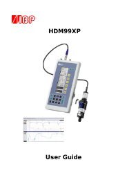
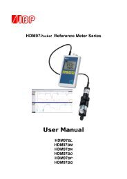
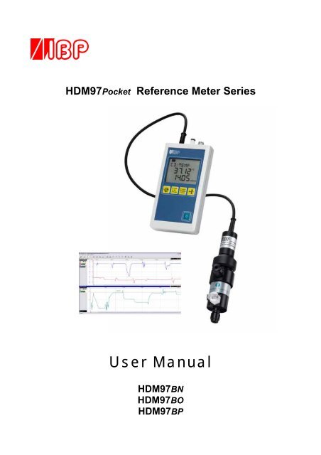
HDM97Pocket Reference Meter Series<strong>User</strong> <strong>Manual</strong>HDM97BNHDM97BOHDM97BP
PrefaceThe information contained in this is subject to change without notice. <strong>IBP</strong> <strong>Medical</strong> GmbH, its distributors and subsidiaries take noresponsibility for any errors or omissions in this document. The contained software is being delivered on the basis of a general licencecontract or in single license. Use or reproduction of the software is allowed only in agreement with the contractual arrangements.Whoever transfers this software and/or this manual on magnetic tape, diskette or any other media, except for the purpose of own use,without written authorization of the <strong>IBP</strong> <strong>Medical</strong> GmbH, is liable to prosecution.Copyright (C) 2008 <strong>IBP</strong> <strong>Medical</strong> GmbH.All rights reservedAll brand names mentioned in this document are property of their respective owners.Publishers: <strong>IBP</strong> <strong>Medical</strong> GmbH <strong>IBP</strong> <strong>Medical</strong> IncIkarusallee 154113 W. St. Charles Ave.D 30179 Hannover Phoenix, AZ 85041GermanyUSAPhone: +49 511 651647 1-866-214-5579Fax: +49 511 652284 1-866-243-0187Internet: http://www.ibpmedical.com http://www.ibpmedical.comE-Mail: support@ibpmedical.com america@ibpmedical.com<strong>Manual</strong> authors:Dipl. Ing. Werner PfingstmannHolger KleinertDocument NumberRevision historyDHDM97.0220.00Rev. 0. 29.05.2008 HKLThis manual is only valid for the software revisions listed below:HDM97BP V 1.00 ...1.09HDM97BO V 1.00 ...1.09HDM97BN V 1.00 ...1.09<strong>IBP</strong>View V 2.000482
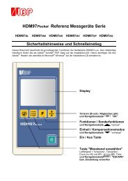
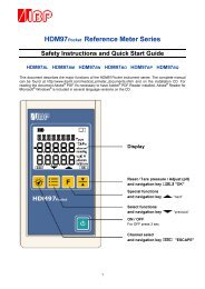
SAFETY INSTRUCTIONSFor your and your patients safety read and consider the safety instructions below carefully• Read the entire manual carefully before using the HDM97Pocket .• Keep the instrument away from unauthorised persons.• Only use the HDM97Pocket as reference instrument to measure Conductivity, Temperature,Pressure and pH depending to it's equipped features.• Never use the HDM97Pocket as a replacement of sensors of a medical device.• Do not use the HDM97Pocket in conjunction with a medical device during a treatment.• Only use the instrument in a dry environment and do not touch it with wet hands.• Make sure that no liquids intrude inside the instrument or it's inlets / outlets.• Always use a clean protection filter for the pressure transducer inlet.• Prevent every mechanical overstraining of electrical wires. Never buckle or pull the cable of theconductivity probe.• If the acquired values seem to be not believable, make sure that the HDM97Pocket is not defective• Prevent electrostatic discharge on the connectors. This can lead to substantial damage of theinstrument. Make sure to be completely discharged before touching the connectors or cablesconnected to the instrument.• Adjust the meter only, if you are familiar with the consequences of the adjustment. Consider thehints for reference solutions in the user manual.• Potentials above 42V against earth ground are dangerous. This potentials can lead to electricalshock and therefore to health hazards. Make sure that none of the connectors has higher voltagethan mentioned before.• The direct connection of earth potential to any connector of the instrument is not applicable forsafety purposes and may substantially damage the instrument. Make sure that the medical deviceitself is properly connected to earth ground according to its instruction manual.• Make sure that the instrument never heats over 60°C / 140°F. Prevent direct sunlight.• Never sterilize the instrument using an autoclave. Danger of explosion of the battery!• Never throw the meter into a fire. Danger of explosion of the battery!• Never open the meter. There are no parts inside you can repair.• Never try to replace or repair the internal battery. Handled in the wrong way these part isdangerous. Extreme risk of fire and explosion!
1Table of contentIntroduction ..................................................................................................................................... 2Application ...................................................................................................................................... 2EC DECLARATION OF CONFORMITY........................................................................................... 3Delivery Content ............................................................................................................................. 4Warranty .......................................................................................................................................... 5Product Overview ........................................................................................................................... 6Measuring Channels ..................................................................................................................................... 6Charging the battery...................................................................................................................................... 7Performing measurements while the battery is being charged..................................................................... 7Flow-through adapter for conductivity and temperature measurement ........................................................ 7Keypad .......................................................................................................................................................... 8Switching on the instrument .......................................................................................................................... 9Display test during start up............................................................................................................................ 9Power saving function ................................................................................................................................... 9Displaying battery charge progress and finish .............................................................................................. 9Battery gauge display during operation....................................................................................................... 10Battery aging ............................................................................................................................................... 10Battery replacement – ONLY BY MANUFACTURER ................................................................................. 10Value adjustment......................................................................................................................................... 12Measuring ...................................................................................................................................... 13Conductivity and temperature measurement .............................................................................................. 13Temperature Coefficients............................................................................................................................ 13Temperature measurement......................................................................................................................... 15Pressure measurement............................................................................................................................... 15Pressure drop measurement....................................................................................................................... 16pH measurement......................................................................................................................................... 16Fundamental information about pH measurement...................................................................................... 16Adjustment and Calibration ......................................................................................................... 17Precautions ................................................................................................................................................. 17Definitions.................................................................................................................................................... 17General........................................................................................................................................................ 17Handling of Reference Solutions................................................................................................................. 18Adjusting the HDM97Pocket ....................................................................................................................... 18Maintenance of HDM97Pocket..................................................................................................... 21Troubleshooting............................................................................................................................ 24Technical data ............................................................................................................................... 25PC Interface ................................................................................................................................... 27USB Interface .............................................................................................................................................. 27Interface parameters for serial COM port emulation................................................................................... 27Driver installation, example for Microsoft ® Windows ® XP Service Pack 2 .................................................. 28Example....................................................................................................................................................... 30<strong>IBP</strong>View.......................................................................................................................................... 31What is <strong>IBP</strong>View.......................................................................................................................................... 31Installation ................................................................................................................................................... 32Quickstart .................................................................................................................................................... 32Disconnect USB .......................................................................................................................................... 32Main Window............................................................................................................................................... 32Selecting hardware...................................................................................................................................... 33Assigning graphs to hardware channels ..................................................................................................... 34List of channels ........................................................................................................................................... 35
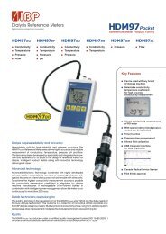
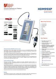
Introduction 2IntroductionThe HDM97Pocket meter series are reference instrument designed for the calibration of medical devices suchas hemodialysis machines. Please read this entire manual carefully before the first use of the instrument.ApplicationDepending on the version the HDM97Pocket may be equipped with up to 4 acquisition channels:Channel HDM97BN HDM97BO HDM97BPConductivity Temperature Pressure pHThe instrument was designed to be used as a dialysis machine maintenance instrument, but can also be usedas laboratory measuring instrument as well as instrument for environmental purposes.This instrument displays measuring values numeric. Graphical displays are available through a PC orNotebook using the optional Software <strong>IBP</strong>View.Using the USB communication interface it is possible to obtain measuring values regardless of theinstrument display's content. These values can be displayed in any way or stored for further processing.
3 EC Declaration of ConformityEC DECLARATION OF CONFORMITYaccording to the Council Directive 93/42/EEC concerning medical devicesManufacturer<strong>IBP</strong> <strong>Medical</strong> GmbHIkarusallee 1530179 Hannoverdeclare under our sole responsibility that thefollowing products:HDM97Pocket Reference Meter SeriesVersion HDM97BNHDM97BOHDM97BPProduct Code: 31.010X.0XX = Depending on Versionmeet the provisions of the Council Directive93/42/EEC concerning medical deviceswhich apply to them.Product ClassificationII BNotified BodyIdentification NumberMedcert GmbHVorsetzen 3520459 Hamburg0482Hannover 27.05.08Responsible:Dipl. Ing. Werner Pfingstmann
Delivery content 4Delivery ContentPos. Description Standard Option1 HDM97Pocket meter 2 Conductivity/Temperature Probe 3 Dialyser Line Adapter 4 Hose for pressure measurement 5 14,00 mS/cm Conductivity Reference Solution 6 Battery charger with wall plug adapters 7 USB interface cable 8 CD - HDM97Pocket with USB drivers, Software and <strong>User</strong> <strong>Manual</strong> 9 Safety instructions and quick start guide 10 pH Probe with solution pH6, 7 and 8 11 Carrying case 12 CD - <strong>IBP</strong>View Data Acquisition Software
5 WarrantyWarranty<strong>IBP</strong> <strong>Medical</strong> GmbH warrants that it will repair or replace, at its option, any defective or malfunctioning partwithout charge for the terms listed below. Parts used for repair or replacement are warranted for theremaining warranty period only.The user must deliver, at its own expense, the product to <strong>IBP</strong> <strong>Medical</strong> GmbH.Parts Warranty –Period*HDM97PocketConductivity/Temperature-Probe24 Month24 Month* from date of delivery noteThe warranty does not cover:• Disposable parts as battery or pH electrode• Annually calibration• Cell cleaning• Defects caused by:1. Modification, alteration, repair or service of the product by anyoneother than <strong>IBP</strong> <strong>Medical</strong> or an authorized service center2. Misuse due to negligence or accident3. Operation or maintenance of the product in a manner contraryto <strong>IBP</strong> instructionsAny express warranty not provided herein, and any remedy for breach of contract that but for this provisionmight arise by implication or operation of law, is hereby excluded and disclaimed. The implied warranties ofmerchantability and of fitness for any particular purpose are expressly limited to the terms mentioned above.Some states do not allow limitations on the duration of an implied warranty, so the above limitation may notapply to you.Under no circumstances shall <strong>IBP</strong> <strong>Medical</strong> GmbH be liable to the original purchaser or to any other personfor any special or consequential damages, whether arising out of breach of warranty, breach of contract, orotherwise. Some states do not allow the exclusion or limitation of special or consequential damages, so theabove exclusion or limitation may not apply to you.This warranty gives you specific legal rights, and you may also have other rights that vary from state to state.For further warranty information, contact <strong>IBP</strong> <strong>Medical</strong> GmbH.
Overview 6Product OverviewpH Pressure Conductivity andTemperature (cable is attached)Measuring ChannelsOnly use accessories provided with the HDM97Pocket . Use of other devices may damage the instrument andwill void the warranty.Conductivity/Temperature ProbeThe Conductivity/Temperature Transducer is a quadropole design for greater accuracy and longevity thanother designs.Pressure transducerTo avoid damage or inaccurate measurement, ensure that no fluids enter the instrument. We recommend theuse of a Transducer Protector for this purpose.pHThe input connector is designed exclusively for pH electrodes. It is optimized for glass electrode single-rodmeasuring cells with a slope of ∆E of 59mV at 20°C. Its absolute maximum allowable input voltage spanextends from -3 Volts to +3 Volts with respect to BNC Shield. Applying any voltage beyond theseboundaries will possibly destroy the instrument.Precautions using the pH Probe inputDue to the high sensitivity of the pH input it can not be fully protected against electrostatic discharge. It canonly be protected by plugging the protective cap to its BNC receptacle. Always attach the protective cap, ifthe pH input is not used. Do not leave the input open, otherwise the circuit inside may be damaged. Theminimum input impedance of the input is 10 Tera Ohms (10*10 12 Ohms). The leakage current is typ. 2 femtoAmperes (2*10 -15 ) Amperes.
7 OverviewCharging the batteryThe HDM97Pocket is internally equipped with a high performance Lithium-Ion-Polymer battery. It can becharged using the external power supply, a PC or a laptop which is connected via the USB cable to theinstrument. The battery of the HDM97Pocket can only be charged from USB ports which are capable ofdelivering 500 mA of current.This is appropriate to most connectors of laptops or PC's. Connecting the meter to apassive (e.g. not externally powered) USB hub, the battery can not be charged andthe communication may not work well. During the charging process the batterysymbol in the display is animated.Performing measurements while the battery is being chargedThe HDM97Pocket can be used for measuring while the battery is being charged. To maintain the dialysismachine and the patient's safety the USB part is isolated to the appliance part of the meter withstanding avoltage of 4000 Volts AC or 6000 Volts DC for at least one minute according to EN60601-1. The appliancepart consists of the conductivity, temperature, pressure and pH channel and its connectors, depending on theversion.ATTENTION: The USB connector is not part of the appliance part.Flow-through adapter for conductivity and temperature measurementNut for openingThe adapter is suitable for measuring pressure, temperature and conductivityin flow-though mode. With immersion usage of the probe it is suitable formeasuring temperature and conductivity concurrently. The preferredorientation of the adapter is vertical. The axial connector must point down(see picture). In flow-through mode the axial connector is to be used as inletmeanwhile the side connector is to be used as outlet. The connection to thepressure transducer inside the HDM97Pocket is accomplished by the lateralconnection above the inlet. Before measurement it is necessary to shake theadapter slightly, so that air bubbles trapped inside can pass off through theoutlet.For immersion usage the probe must be unscrewed from the flow-throughadapter. To accomplish that do not turn the upper shank, the probe may bedamaged. Only turn the nut as shown in the picture left.DialysatepressureoutletNever touch the electrode surfaces with yourfingers or other objects.Do not buckle the cable of the probe.The minimum allowed bending radius is3 cm e.g. 1¼ inches.
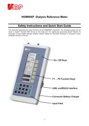
General 8KeypadMain functionsThe keypads main functions of the HDM97Pocket are listed below:Keyfor switching the instrument on and offKeyfor selecting the channel CD/TP ; TP ; PRESSURE ; pHKeyfor selecting the unit to display.Keyleads to channel dependent special functionsKeyto tare the pressure transducerThe keypad layout is shown in the left picture.The keys , and have different sub functions depending on the channelcurrently displayed. These sub functions are explained in chapter "Measuring"Additional functionsThe yellow keys below the display can be used toset values and navigate through menu options orsetting. These functions become available whenthe symbols shown in the right picture appear at thebottom of the display.Cancels the current setting or selection and returns to measuring mode.Decreases a value or selects the previous option in a menu or a setting.Increases a value or selects the next option in a menu or a setting.Applies a value or a selects an option in a menu or a setting.
9 GeneralSwitching on the instrumentThe instrument is switched on and off by pressing thekey.Display test during start upImmediately after switching on the instrument the display shows allpossible segments dark for two seconds. Compare the display withthe picture on the right side. Do not use the instrument further if youdiscover any missing segment, because wrong values could bedisplayed which may lead to misreading.The content of the display must be shown exactly like this pictureright from this text.Power saving functionThe HDM97Pocket switches off automatically if the battery is empty. If enabled, it also switches off after aspecified time if one of the conditions listed below becomes true for the specified time period.• In pressure mode: The value remains 0 for the specified time period• In conductivity mode: The conductivity is 0 µs/cm for the specified time period• In pH mode: The pH probe is not connected for the specified time periodDisplaying battery charge progress and finishIf the battery is being charged the symbol at the left top corner in the display is animated in 4 steps. There isa delay of one second displaying each step. After the last step has been displayed the animation starts fromagain like illustrated in the picture below. After the battery has been charged up to its maximum capacity, the inner 3 columns of the battery symbolstart to blink in a one second period as shown is the illustration below.
General 10Battery gauge display during operationIf nothing is connected to the USB port during operation the internal battery is used to supply power to theinstrument. The battery symbol in the left top corner of the display shows the remaining capacity of theinternal battery. The combinations have the meanings listed below:The battery is 100% full.The battery has approx. 2/3 of its capacity left.The battery has approx. 1/3 of its capacity left.The battery is empty, approx 10% is left.If this symbol starts flashing the battery is totally empty and the meter will switchoff shortly.Battery agingThe battery technology of the HDM97Pocket is based on Lithium-Ion-Polymer technology. This technologyhas many advantages compared with Nickel-Metal-Hydride technology which are lower weight, smaller size,longer life, no memory effect and higher efficiency. However, after a couple of years (5 years estimated) thebattery's capacity will start decreasing.Battery replacement – ONLY BY MANUFACTURERDo not try to replace the battery by yourself. The battery is mounted directly onto the main PCB inside theHDM97Pocket, and the main PCB itself contains the battery protection circuit. If the battery is not handled inthe right way, there is extremely danger of fire and explosion. Therefore, this battery can only be replacedfrom <strong>IBP</strong> personnel who have run through a special training in handling Lithium-Ion batteries.
11 Base InstallationBasic settingsTo invoke the installation menu please follow the steps below:1. Switch off the meter using the key.2. Switch it on again using the same key.3. Immediately press the key once during the display test.4. After this procedure the instruments starts the basic settings dialog instead of entering any measurementfunctions.5. In the basic settings dialog the user is able to adjust a variety of settings.These are:ParameterAUTO-OFFLANGUAGECAL-RESPHTEMPBEEPDescriptionSelects the auto power off delay time or disables this feature.Selects the display languageReplaces the user calibration dataset with the factory calibration datasetEnables or disables the pH channel "PH"Enables or disables the single temperature channel "TEMP"Enables or disables the keypad acknowledge beep→AUTO-OFF→ OFF → disables function→ 30 MIN → 30 minutes delay→ 60 MIN → 60 minutes delay→ 90 MIN → 90 minutes delayThenorto apply this setting,to discard this setting.→LANGUAGE→ DEUTSCH → German language→ ENGLISH → English languageThenorto apply this setting,to discard this setting.
Base Installation 12→CAL-RES→Press 5 seconds until the counter in the display reaches zero.Then a calibration dataset reset will be performed. This takesa couple of seconds. The instrument performs a restart afterwards.→ PH (or TEMP)→ ON → pH channel (or temp-channel)enabled→ OFF → pH channel (or temp- channel)Thenorto apply this setting,to discard this setting.disabled→BEEP→ ON → keypad beep enabled→ OFF → keypad beep disabledThenorto apply this setting,to discard this setting.Value adjustmentThe adjustment of values is done via the navigation keys and . By pressing and holding downone of these keys the last (right) digit of the value will be incremented or decremented depending on the key.If this digit reaches the boundary it remains 0 and the next digit will begin to change. If the key is beingreleased and pressed again the procedure will start again beginning with the last digit.Example showing a value, which has an allowable range from 0.00 to 7.50:Display: 0.00 ; navigationkey is hold down:Order of value incements (every change follows with a delay of 0.3 seconds):0.01→0.02→0.03→0.04→0.05→0.06→0.07→0.08→0.09(carry-over)0.10→0.20→0.30→0.40→0.50→0.60→0.70→0.80→0.90(carry-over)1.00→2.00→3.00→4.00→5.00→6.00→7.00→7.50(Max value reached)If the value will exceed the range limits (in this case from 7.00 to 8.00) the value will be truncated to themaximum allowed value, 7.50 in this particular example. The Symbol will become blank and themeter does not react on the corresponding navigation key. The values can only be changed down to 0.00using the other key.
13 Adjustment and CalibrationMeasuringBy pressing the key the user can select between all available channels of the HDM97Pocket .These channels are• Conductivity and temperature Display "CD/TEMP"• Temperature Display "TEMP" (if enabled)• Pressure Display "PRES" (only HDM97BP and HDM97BO• pH Display "PH" (only HDM97BP, if enabled)Conductivity and temperature measurementIn this mode the display shows "CD/TEMP" in the upper line, the temperature value in the middle line andthe conductivity value in the bottom line.By pressing the keythe user can choose the temperature coefficient.Temperature CoefficientsThis is a topic that is frequently misunderstood and often neglected in hemodialysis.A solution’s conductivity will change according to temperature. With increasing temperatures, the measuredsolution’s conductivity will increase, too. To achieve meaningful measurement results, the conductivityvalue displayed is compensated to 25°C. In other words, the display is always converted to a solutiontemperature of 25°C. The temperature coefficient which the displayed value is compensated with isexpressed as %/°C. Unfortunately however, different solutions also have different temperature coefficients.To achieve an exact display, the instrument will have to be adjusted to the temperature coefficient of thecurrent solution. The average temperature coefficient for dialysates is 2.07 %/°C.Listed below are the temperature coefficients used by most major hemodialysis machine manufacturers. Werecommend that you double check this data with documentation from your machine’s manufacturerDisplay Machine Manufacturer Temperature CoefficientBAXTER Baxter (Europe Machines) 2,20 %/KBELLCO Bellco 2,10 %/KB.BRAUN B.Braun 2,10 %/KFRESENI Fresenius 2,10 %/KGAMBRO Gambro (AK-Type Machines) 2,07 %/KGAMBRO Gambro Phoenix 2,07 %/KHOSPAL Hospal 2,07 %/KNikkisoNIK BIC Bicarbonate Conductivity 2,20 %/KNIK ALL Gesamt- Conductivity 2,05 %/KSTANDARD2,07 %/KUSER TC(Your choice)For naturally occurring solutions, a value of 1.97 %/°C is frequently used. Many measuring devices notspecially tailored to dialysis will use this value.The calculation below shows the drastic effects of an incorrect temperature coefficient.
Adjustment and Calibration 14Example calculation for an incorrect temperature coefficient, using a dialysate with a temperature coefficientof 2.07 %/°C:Conductivityof solutionTemperatureof solutionTemperature coefficientof meterMeterdisplayDifferencein valuesmS/cm°C%/KmS/cm%14,00 37,0 2,07 14,00 0,0014,00 37,0 1,97 14,17 1,21Which temperature coefficient you should useFirst of all please double-check the Temperature coefficient with the machine manual.If you have machines from one manufacturer only in your use the temperature coefficient that the dialysismachine uses for compensation.If you have different types of dialysis machines in your unit the best solution is to use a temperaturecoefficient of 2.07 %/°C for all machines. This avoids confusion with different readings of the conductivityon different machines.Selecting the temperature coefficientBe aware that changing the temperature coefficient will lead to changes in valuesdisplayed by the meter. Therefore only change the temperature coefficient, if you are fullyaware of its consequences. If the temperature coefficient setting is wrong it will lead tofalse display values and at the end to hazards for the patient.The HDM97Pocket enables the user easy to choose between vendor specific temperature coefficients as wellas a free adjustable value called "USER TC". To achieve this press the key while in Conductivity /Temperature measuring mode. Use the and navigation key to select between the machinemanufacturers. By pressing the navigation key the setting will be applied. Pressing thenavigation key discards the setting and the meter returns back to measuring mode.Adjustment of customer specific temperature coefficient "USER TC"Pressing the navigation key while adjusting the temperature coefficient to "USER TC" theHDM97Pocket enters a second dialog to adjust the value itself instead of directly going back to measuringmode.→USER TC→→enters the dialog to adjust the user temperature coefficientcancel and discard settingDisplay:USER TC2.070 (Example old value)2.071 (Example new value, navigation key has been pressed once)Keys: → increments current value→decrements current value
15 Adjustment and Calibration→→Applies the value to USER TC and chooses USER TC as newtemperature coefficientDiscard adjustment and goes on using the last active temperaturecoefficient settingTemperature measurementThis mode is only available if enabled in the basic settings menu. This mode exists to save power in caseconductivity measurement is not needed.By pressing the keyyou can switch between unit °C and °F.Pressure measurementIn this mode the instrument displays the pressure in the middle line.UnitBy pressing the key you can choose between units mmHg, mbar and kPa. The values will berecalculated automatically. It is not necessary to tare or adjust the meter if the unit is changed.Offset balancing (tare)Caused by drift of the pressure probe, the pressure display may sway slightly around zero. The HDM97Pocketis equipped with a tare function which sets the value to zero if drift occurs. While performing this functionthere must not be any pressure on the pressure transducers inlet. This is assured when the pressure tube is notconnected. Then the environmental pressure represents zero.Procedure1. Make sure there is no pressure applied to the pressure transducer2. Press and hold down the key until the upper display line shows "ZERO", this will takethree seconds3. The measuring value is not set to zero.
Adjustment and Calibration 16Pressure drop measurementIn pressure measuring mode the drop measurement function can be invoked by pressing thekey.Display: PRES 60 (60 means: 60 seconds countdown)406.2 (start value example)Keys: → Stores the current value internally and starts a 60 secondcountdown. The bottom line displays the difference betweenthe current value and the stored start value→Cancels the function and return to normal pressure measurement.After the countdown has finished the instrument beeps 5 time and displays the following values:Display: PRES 00400.0 (example value after 60 second countdown)- 6.2 (example internally stored start value - end value after 60 seconds)Key: → Returns back to normal pressure measurement.pH measurementThe HDM97Pocket can perform pH measurement in four different ways of temperature compensation.By pressing thekey you can choose between these four compensation modes.• pH at 20°C Display "PH 20.0 °C"• pH at 25°C Display "PH 25.0 °C"• pH at 37°C Display "PH 37.0 °C"• pH compensated by simultaneous measured temperature Display "PH"Fundamental information about pH measurementFor measuring pH, a combined electrode is used. Combination pH electrodes are combinations of onereference electrode and one measuring electrode in a glass tube. The pH value in the dialysate is measured byan unbreakable pH-electrode. The glass body is protected with a plastic coat and due to the jelly-electrolytefilling,it is maintenance-free. This electrode’s diaphragm must be stored in 3 mol/l KCl-solution. Theprotective cap must be refilled every three to four weeks to prevent the electrode from drying out. Before usethe electrode must be checked for exterior damage and crushed glass. Crusts caused by leaking electrolytecan be removed easily by rinsing with reverse osmosis-treated water.The sample volume should be 100 ml of dialysate or 1 liter of untreated water. The sample should be pouredinto a clean glass container with a tube or hose, coming into as little contact with air as possible. The pHvaluemust be measured immediately in the same container. Make sure that the display stabilizes before thevalue is read. In stirred solutions the response rate is faster; the value, however, must be measured at restingfluid.The pH-electrode must be dabbed only with a lint-free cloth and never rubbed dry. Rubbing destroys thejelly layer on the glass surface which results in a longer response time for the electrode.Pressure and fluid currents have considerable influence on the pH measurements. For high accuracypH measurement it is essential to take the pH measurement in a resting solution at environmentalpressure.
17 Adjustment and CalibrationAdjustment and CalibrationPrecautionsUse the adjustment functions only if you are fully aware of their consequences.Wrong adjustment values will lead to false measurement values and inconsequence these false values lead to hazards for patients.DefinitionsAdjustmentAn adjustment is a process in which properties of a measuring device are change in that way that its scale ordisplay reads the same as an reference device or standard.CalibrationCalibration is the process of establishing the relationship between a measuring device and the units ofmeasure. This is done by comparing a device or the output of an instrument to a standard having knownmeasurement characteristics. For example the length of a stick can be calibrated by comparing it to astandard that has a known length. Once the relationship of the stick to the standard is known the stick can beused to measure the length of other things. Adjustments are checked by performing a calibration.GeneralAccording to ISO 10012-1 “General Quality Assurance Requirements for Measuring Equipment" the errorattributable to calibration should be as small as possible. In most areas of measurement, it should be notmore than one third and preferably one tenth of the permissible error of the confirmed equipment when inuse. In other words the accuracy of the references to adjust or calibrate the HDM must have at least a treetimes higher accuracy.After a channel has been adjusted it is necessary to calibrate it afterwards. If inconclusive orincomprehensible values are shown in the display it is highly recommended to do a calibration.The procedure of calibration and adjustment is slightly different for each channel. Proceed with anadjustment only if you have fully understood the procedure.• Conductivity is adjusted only at one sampling point. No further points are needed due to the highlinearity of the conductivity probe.• The temperature sensor does not drift. Normally there is no adjustment necessary. The adjustment isdone by using two sampling points.• The pressure transducers drift is linear within its tolerances, so there is a tare function (see chapter"Measuring"). Normally there is no adjustment necessary. The adjustment is done by using sevensampling points.• Due to the kind of their technology it is necessary to adjust pH probes periodically. This is doneusing two sampling points.If you are uncertain of entering the correct adjustment values you can discard the values and cancel theadjustment procedure at any time.
Adjustment and Calibration 18Handling of Reference Solutions<strong>IBP</strong> <strong>Medical</strong> standard solutions are produced under ISO13485:2003 quality management. They are traceableto NIST and PTB Standards Reference Materials and are sealed with tamper-evident packaging.To ensure standard solution and calibration/verification accuracy• Keep solutions tightly capped to avoid evaporation• Do not return used solutions to the storage bottle• Do not remove solutions from their original bottle• Keep the solutions in a cool place• Use only fresh reference solutions for calibration and verification• Use the solution immediately after pouring, evaporation will cause errors• Discard solution the appropriate number of days after opening the bottle• Discard solution after the expiration dateAdjusting the HDM97PocketUse these functions only if you are fully aware of their consequences. Wrongadjustment values will lead to false measurement values and in consequencethese false values may lead to hazards for patients.The entire procedure is guided by using software, it is not necessary to open the instrument. To invoke theadjustment menu first select the channel you want to adjust. Then press and hold down the keys und atthe same time for at least 5 seconds. If you want to cancel the operation press navigation key .TemperatureTemperature adjustment is done using 2 sampling points. The order of the adjustment points is preassignedand the value range of each point is restricted by boundaries.Point Display Temperature Boundaries1. "TP1" 25.000 °C ±1.500 °C2. "TP2" 55.000 °C ±1.500 °CNormally an adjustment is not necessary because the sensor has no drift.The temperature sensor must be dipped into a liquid with known temperature. This known temperature mustbe adjusted using the navigation keys and . It is mandatory to wait until the measuring valuebecomes stable. After the measuring value finally becomes stable the adjustment point can be applied usingthe navigation key . The instrument jumps immediately to the next adjustment point, so the procedurecan be repeated. After the last adjustment point has been applied the instrument displays "CAL OK" in theupper line of its display. If the adjustment is not correct, the instrument displays "CAL ERR" in the displayalong with a long warning beep. In this case the adjustment values will be discarded and the procedure has tobe started from the beginning. A failed adjustment can also be an outcome of a defective instrument.
19 Adjustment and CalibrationPressureThe pressure transducer has no nonlinear drift so an adjustment is normally not necessary.Use the tare function to balance the pressure transducers environmental pressure change drift.The pressure channel is adjusted using 7 sampling points. This improves the accuracy of the pressuremeasurement, because it recalculates slightly nonlinearities of the pressure transducer. The order of theadjustment points starts with point 1 and is preassigned. The value range of each point is restricted byboundaries.Apply the pressure values to the instruments pressure transducer inlet as shown in the table below. Adjust thevalue of your reference or standard to the HDM using the navigation keys and . It is mandatoryto wait until the measuring value becomes stable. After the measuring value finally becomes stable theadjustment point can be applied using the navigation key . The instrument jumps immediately to thenext adjustment point, so the procedure can be repeated. After the last adjustment point has been applied theinstrument displays "CAL OK" in the upper line of its display. If the adjustment is not correct, the instrumentdisplays "CAL ERR" in the display along with a long warning beep. In this case the adjustment values willbe discarded and the procedure has to be started from the beginning. A failed adjustment can also be anoutcome of a defective instrument.Point Display Pressure Boundaries1. "PR1" -500 mmHg ±10 mmHg2. "PR2" -250 mmHg ±10 mmHg3. "PR3" 0 mmHg ±10 mmHg4. "PR4" 150 mmHg ±10 mmHg5. "PR5" 300 mmHg ±10 mmHg6. "PR6" 900 mmHg ±10 mmHg7. "PR7" 1500 mmHg ±10 mmHgConductivityThe adjustment of the conductivity channel is done by adjusting the cell parameter. To achieve this only oneadjustment point is necessary.Point Display Cell parameter Initial Conductivity1. "CD xx.xx°" 0.xxxx 14.000 mS/cmFirst of all set the displayed adjustment value to the value of your reference solution. Then make sure that thesolution has a stable temperature of exactly 25.00 °C. Wait until both the temperature and the conductivityvalues in the display become stable before pressing the navigation key . After that the cell parameteris being calculated and will be stored in the instrument.
Adjustment and Calibration 20pHIt is necessary to adjust th pH channel before each usage. It is achieved using two adjustment points.Point Display Initial pH value1. "PH1" 6.002. "PH2" 8.00A pH adjustment has to be done according to the following instructions:Set the mode of temperature compensation to the mode you have to use afterwards. Prepare 2 buffersolutions which should not be more different than 2 pH values from each other and which are around thevalue you expect from your measurement. If you expect to measure values around pH 6 then use the pH 5and pH 7 buffer solutions for instance. The adjustment has to begin with the lower pH value and to end withthe higher pH value. Preset the buffer solutions value using the and navigation keys.Before dipping the probe into the buffer solution it has to be flushed with distilled water and dried bycarefully dabbing it. Depending on the mode you have chosen the temperature sensor must also be flushedand dried. Then dip both into the buffer solution and wait until the measuring values become stable. In thiscase apply the value using the navigation key . Flush and dry the probes before continuing with thesecond adjustment point. The second point is adjusted in the same way. After the last adjustment point hasbeen completed the instrument displays "CAL OK" in the upper line of its display. If the adjustment is notcorrect, the instrument displays "CAL ERR" in the display along with a long warning beep. In this case theadjustment values will be discarded and the procedure has to be started from the beginning. A failedadjustment can also be an outcome of a defective instrument.Cancelling the adjustment procedureIf you are uncertain to have entered the correct values at any step in the adjustment procedure you can cancelthe process at any time. Cancelling the operation will discard the adjustment values.Restoring adjustment values with factory adjustment valuesIf you have failed to adjust the instrument properly, you can overwrite the user adjustments with a factoryadjustment value set which has been stored into the instrument during production process. Please refer tochapter "Basic settings".
21 MaintenanceMaintenance of HDM97PocketGenerally the HDM97Pocket can be considered as an easy-care instrument. Like all measuring instrumentsthere is a minimum of maintenance and care necessary to ensure that all functions work flawlessly.Operate the instrument only in a dry environment, and do not touch it with damp hands. Ensure that no fluidsintrude into the interior of the device, or into the sockets at the front.There are no parts in the HDM97Pocket which you can repair yourself. Contact our technical support team inthe event of any malfunction. If the device should become damaged, or malfunction, send it to <strong>IBP</strong> or yourdistributor for repair.StorageKeep the device in a dry place. Suitable is, for example, the original packaging in which you have receivedthe HDM97Pocket , or the carrying case offered by <strong>IBP</strong> as accessory. If you do not use the device over alonger period of time, you should connect it to the included charging device about every month for one hourto avoid exhausting the batteries.CleaningNever clean the device with any fluids! In case of pollution you can wipe the surface of the HDM97Pocketwith a dry and clean cloth. For measurements in the lower conductivity range, the cleaning of theconductivity/temperature measuring cell is recommended. Remove water-soluble substances by rinsing withdeionized water, fats and oils with warm water and household dish washing detergent. Lime and hydroxidcrusts can be dissolved by a 10% citric acid solution. In each case, the measuring cell needs to be washedwith deionized water after the cleaning. Basically, the conductivity measuring cell does not decay over time.Particular measuring media (for example, strong acids and caustic solutions, organic solvents), or too hightemperatures shorten the service life considerably, and/or lead to damage.Caring for the conductivity/temperature electrodeThorough cleaning of the electrode is particularly important for measuring low conductivities.Water-soluble substances must be removed by rinsing with deionized water. Remove lime deposits with a10% citric acid solution. To do this, immerse the electrode in the solution for 2 hours at room temperature,then rinse it thoroughly with deionized water. Do not touch the electrode surface with your fingers. Ifnecessary, clean the surface with acetone.
Maintenance 22Calibration periodWhen delivered new from the factory, each device is adjusted and calibrated before shipment. To ensurereliability, we recommend the following intervals for verifying calibration:ParameterTemperatureConductivityPressurepHCalibration periodOnce per yearOnce per yearOnce per yearDaily before each useA complete function test and calibration of the device should be done once a year.According to ISO 10012-1 “General Quality Assurance Requirements for Measuring Equipment" the errorattributable to calibration should be as small as possible. In most areas of measurement, it should be notmore than one third and preferably one tenth of the permissible error of the confirmed equipment when inuse. In other words the accuracy of the references to adjust or calibrate the HDM must have at least a treetimes higher accuracy.For liability reasons you should not carry out these tests and calibration and verification yourself. If <strong>IBP</strong>performs the calibration, you will receive a calibration certificate in accordance to ISO9001 whichdocuments the calibration/verification results.
23 MaintenanceTolerancesFor calibration, the instrument must met the deviations listed below.Channel Reference Value Allowed deviation Notes25,00 O C ± 0,05 O C34,00 O C ± 0,05 O CTemperatureConductivityPressurepH37,00 O C ± 0,05 O C40,00 O C ± 0,05 O C55,00 O C ± 0,07 O C80,00 O C ± 0,07 O C74,00 µS/cm ± 0,60 µS/cm147 µS/cm ± 0,60 µS/cm720 µS/cm ± 6,00 µS/cm1410 µS/cm ± 6,00 µS/cm2,77 mS/cm ± 0,03 mS/cm6,70 mS/cm ± 0,03 mS/cm12,88 mS/cm ± 0,03 mS/cm16,00 mS/cm ± 0,03 mS/cm+ 190,00 kPa ± 0,13 kPa+ 110,00 kPa ± 0,13 kPa+ 50,00 kPa ± 0,13 kPa+ 40,00 kPa ± 0,066 kPa+ 25,00 kPa ± 0,066 kPa+ 10,00 kPa ± 0,066 kPa0,00 kPa ± 0,066 kPa Open inlet- 10,00 kPa ± 0,13 kPa- 50,00 kPa ± 0,13 kPa- 80,00 kPa ± 0,13 kPa355,2 mV = pH 1 ± 0,02 ∆E=-59,2mV/∆pH177,6 mV = pH 4 ± 0,02 ∆E=-59,2mV/∆pH118,4 mV = pH 5 ± 0,02 ∆E=-59,2mV/∆pH59,2 mV = pH 6 ± 0,02 ∆E=-59,2mV/∆pH0 mV = pH 7 ± 0,02 ∆E=-59,2mV/∆pH- 59,2 mV = pH 8 ± 0,02 ∆E=-59,2mV/∆pH-118,4 mV = pH 9 ± 0,02 ∆E=-59,2mV/∆pH-177,6 mV = pH 10 ± 0,02 ∆E=-59,2mV/∆pH-355,2 mV = pH 14 ± 0,02 ∆E=-59,2mV/∆pH
Troubleshooting 24TroubleshootingProblem:USB cable connected, but the battery is not being chargedReason:Solution:Reason:Solution:USB port of laptop does not provide enough powerConnect the meter to the battery charger or a USB port which is able to supply atleast 500 mA.USB cable brokenReplace cableProblem:The meter can not be switched onReason:Solution:Reason:Solution:Battery is empty.Connect the meter to a battery charger or an USB port.Other problems.Press and hold the on/off key for at least 5 seconds. The meter will perform a"Low-Level-Reset" and should start afterwards.Problem:The meter powers off itself after a couple of seconds.Reason:Solution:Battery empty.Connect the meter to a battery charger or an USB port.Problem:pH channel can not be selected (only Version BP)Reason:Solution:pH channel is disabled in basic settings menu.enable pH channel in basic settings menu.Problem:Pressure value does not tare / zero balancing does not work (only versions BO and BP)Reason:Solution:There is still pressure applied to the pressure transducer.Disconnect pressure hose directly at meter.
25 InterfaceTechnical dataConductivity0 to 30,0 mS/cm, 4-Pole probe,Resolution and accuracy:Range Resolution Accuracy0.0 – 200 µS/cm 0,1 µS/cm ± 0,6 µS/cm201 - 1999 µS/cm 1 µS/cm ± 6µS/cm2,00 – 30 mS/cm 0,01 mS/cm ± 0,03 mS/cmReference temperature 25° CTemperature compensation is 2,070 % per KelvinAdjustable from 0.00 to 4,00 %/KelvinOr selectable from dialysis machine manufacturer preset values.TemperatureRange0 … 100 °C,Resolution 0,01 °CAccuracy25 … 40°C ± 0,05°Cotherwise ± 0,1°CPressureRangeResolutionAccuracy-700 … 1900 mmHg, 2.5 Bar1 mmHg± 2 mmHg (20 … 23 °C)pHRangepH 0 … 14 ; max. slew rate 70mV (118%) / ∆pHResolution pH 0,01Accuracy pH ± 0,02DC input impedance min. 10 Tera Ohm (min. 10 * 10 12 Ohm)Input leackage current typ. ± 2 fA ; max. ± 2 pATemperature compensation with temperature measurement or preset values to choose from.Internal power sourceInternal Li-Ion-Polymer battery, rechargeable with USB 5V DC / max. 500mAOperating time, depending in channel, up to 60 hours.Nominal Voltage3,7 VMax. charge voltage 4,2 V (internally generated an monitored)Capacity850 mAh or 3,1 WhBattery charge timeapprox. 3 hoursExternal power supplyInput voltageOutput voltagePlug100-240 V AC/ 50-60Hz5 V DC, 1000 mA LPSMini USB A-Plug
Interface 26Degree of protectionMeterIPX1Conductivity probe IP66 , max. 0,5 m immersion depth, max. 5 minSize and weightSizeWeight165 x 82 x 33 mm400 gr. without battery charger, including conductivity/temperature probeThese technical data may be changed without notice!
27 InterfacePC InterfaceUSB InterfaceThe USB interface of the HDM97Pocket is electrically isolated from the appliance part. Two drivers areneeded for installation. One driver is made for invoking the interface like any other USB device and the otherdriver is used to emulate a serial COM port device.Interface parameters for serial COM port emulationThe HDM97Pocket uses the preset values below for serial COM port emulation:PropertyBaud rateValue9600 bpsData bits 8ParityNoneStop Bit 1Handshakenone
Interface 28Driver installation, example for Microsoft ® Windows ® XP Service Pack 21. Insert the Installation-CD in the CDor DVD drive of your computer.2. Connect the HDM97Pocket via the USB-cable with afree USB port of the running computer. It does notmatter whether the instrument is switched on or off.3. A "Found New Hardware Wizard" Window willappear on the screen like that right here from the text.4. Choose "No, not this time" and afterward click onthe button "Next".5. Driver source selection dialog: Choose "Install froma list or specific location (Advanced)", and click onthe "Next" button afterwards6. Choose "Search fort he best driver in theselocations" and check "Include this location in thesearch:". Then use the "Browse" button andchoose your CD/DVD drive's letter and add the folder"drivers" to it. In the given example on the right sidethe CD/DVD driver has drive letter D:\" assigned.Click on the "Next" button afterwards.7. Windows Logo Test : Choose "ContinueAnyway".
29 Interface8. The driver installation is in progress. This cantake a couple of minutes.9. The driver installation was successful, click onthe button "Finish" to complete theprocedure.After you have finished this procedure another similar Wizard will popup. Do exactly the same you did inthe first procedure as described earlier. One installation is for the COM port emulation, the other installationis for the USB interface itself.Checking the driver installation (optional)The USB interface of the HDM97Pocket emulates a serial COM port and offers a proprietary interface tocommunicate directly with the USB interface.Use the "My Computer/Manage" function to open theDevice Manager and search for a Group called "Ports(COM and LPT)". You should find an entry called"USB HDM Interface". At the end of the line youwill find the number of the associated COM port (inthis case "COM3").In addition you will find the USB communication interface in the Group "USB-Controller" It is named " USB HDM Interface ".
Interface 30Data transferTo receive measurements from the HDM97Pocket via the USB interface, the following abbreviations must besent via the interface. The entire communication takes place in readable ASCII-characters.Commandto HDM97PocketHDMCMOHDMCMFHDMEIHhdmReactionof the HDM97Pocketactivates the data transferdeactivates the data transfertransmits all unitstransmits the valuesFormat of the valuesConductivity in S/cmTemperatur in °CDruck in mmHgpHCR, LF9 signs7 signs9 signs5 signs2 signsExampleDie Trennung der einzelnen Werte erfolgt durch /Command „hdm“ – HDM sendet: 0.1234567/123.123/ -12345.12/12.12 + CR LFCommand „HDMEIH“ – HDM sends: S/cm,°C,mmHg,pH CR LF
<strong>IBP</strong>View 31<strong>IBP</strong>ViewWhat is <strong>IBP</strong>View<strong>IBP</strong>View can be obtained optionally for the HDM97Pocket and can be used as well for other HDMinstruments. A demo version is included in the folder \Software\ on the driver CD. This demo can not save,export or print and the acquisition time is limited to 30 seconds.<strong>IBP</strong>View is a data acquisition software, which records and plots measured values from a HDM97Pocketdevice. It works with a USB connection of the HDM97Pocket. The software can also be used with severalhardware devices, such multimeters from Voltcraft or Metex.<strong>IBP</strong>View is compatible with Microsoft ® Windows ® 2000, Microsoft ® Windows ® XP and Microsoft ®Windows ® Vista ®Several curves can be plotted into a single diagram. Several diagrams can be arranged on one or more pagesif necessary.Plot options like pen width or pen color can be used to create perfectly styled diagrams. You can even createyour own plotter designs.Comfortable zoom functions are available on a single click to analyse plot details or to return to the plotsoverview.Setting markers makes it easy to read differential values of a plot, or to determine the amplitude or period ofa sampled signal.A comfortable preview allows you to add comments or project data when printing diagrams.Export functions can be used to use measured data with other applications like MS-Excel, etc.The help function of <strong>IBP</strong>View includes instructions for basic operations using a small project as an example.If you follow these instructions it will be a good start for you in understanding the basics.
<strong>IBP</strong>View 32InstallationInsert the CD „<strong>IBP</strong>View“ into the CD-Drive. The installatio will start automatically. In case open thedirectory „SETUP“ and start setup.exe. On then first menu select the language, the installation process is selfexplaining.QuickstartOn the CD „HDM97Pocket“ you will find templates for all versions of the HDM97Pocket . These templatesare prepared fort wo, three and four measuring channels. Do not use a template which is prepared for moremeasuring channels than measuring channels meter has.Disconnect USBBefore terminating the USB connection please terminate the <strong>IBP</strong>View software. Disconnecting with runningdata acquisition may end in a system freeze.Main WindowGeneralThis manual describes only the basic functions which are necessary to get familiar with <strong>IBP</strong>View. Furtherinformation can be obtained using the Software's help function. <strong>IBP</strong>View is intentionally not limited toHDM instruments. It can be configured independently and therefore achieves its maximum flexibility to beready for future <strong>IBP</strong> products.Hardware Interface<strong>IBP</strong>View uses serial COM ports for communication. This can be common RS232 serial interfaces like manymultimeters on the market use, or, like the HDM97Pocket virtual serial ports based on USB. Using virtualCOM ports it is necessary to define the number of the port once (COM1, COM2, COM3, etc.). The COMport number of the hardware is defined automatically during the driver installation. The application mustknow this number, in order to communicate with the device. For obtaining the number for the HDM97Pocketplease refer to chapter "Checking the driver installation". In this example "COM3" is used. Be aware thatconnecting the HDM97Pocket to different physical USB receptacles will result in different COM portnumbers, one for each receptacle. This is done to make multiple HDM meters work with one computerconcurrently.
33 <strong>IBP</strong>ViewTemplate projectsProject files are named in the way "[Name].ibp". To get an easy start with <strong>IBP</strong>View there are preconfiguredversion specific templates for each type of instrument. These templates include all common setting for startworking with the application. Only the number of the COM port must be adjusted to the number the driverinstallation has chosen if it is not coincidentally the same number is used. For help to select the right COMport read also chapter “Checking the driver installation“.Templates are available on the CD “HDM97Pocket“.Selecting hardware1. Click on "Hardware" in the main windowand choose menu entry "Define…". Then awindow named "Hardware configuration"like that right from this text will open. Openin the left box "Supported hardwaredevices" the group "<strong>IBP</strong> <strong>Medical</strong> GmbH",click on the entry "<strong>IBP</strong> <strong>Medical</strong> Devices"and then drag and drop it to the right box"Existing hardware devices".2. After the drag and drop procedure a window opens which can be used to set thenumber of the serial COM port and the number of channels for the instrument. Fora HDM97BP four channels are possible. In case the pH channel is disabled in thebase settings of the HDM97BP, the meter has only three measuring channels.Selecting of a wrong channel number than the meter really provides will result in anot working data transmission.To find out which COM-Port the USB-Driver has selected please select theWindows System Manager and than theDevice Manager. Under group "Conncetions(COM and LPT)" you should find the port.3. After this the device is displayed in theright box. Other hardware devices can beadded if needed. Click on "OK" to close thewindow.
<strong>IBP</strong>View 34Assigning graphs to hardware channelsIn the main window the list of channels is located left. The assignment of a particular graph to a specifichardware channel is done by performing a double click on the channel's name in the list.This double click leads to a dialog"Cannel configuration" (picture in themiddle). You can change Name, Basicunits, Decades, Ranges and much more.By clicking on the button "Assign" youcan assign each graph a hardware channel,like shown in the picture right.For conductivity please use the base unitS/cm and select for example “m (milli)” asDecade to show the values in mS/cm.
35 <strong>IBP</strong>ViewList of channelsDepending on the version the HDM97Pocket is equipped with up to 4 channelsChannel Description Range Unit HDM97BN HDM97BO HDM97BP1. Conductivity 0.000 .. 30.00 mS/cm 2. Temperature 0,00 .. 100,00 °C 3. Pressure -750,0 .. 1900 mmHg 4. pH 0 .. 14 (ohne) If not disabledIf the wrong number of channels is selected the data transmission will not work correctly. In case the pHchannel is disabled in the base settings of the HDM97BP, the meter has only three measuring channels.