omnilock access control systems installation instructions
omnilock access control systems installation instructions
omnilock access control systems installation instructions

Create successful ePaper yourself
Turn your PDF publications into a flip-book with our unique Google optimized e-Paper software.
SECURITY<br />
®<br />
OMNILOCK<br />
DEVICES ACCESS CONTROL SYSTEMS<br />
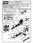
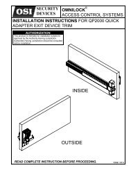
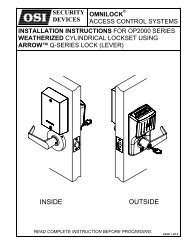
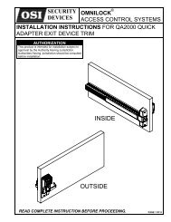
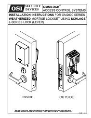
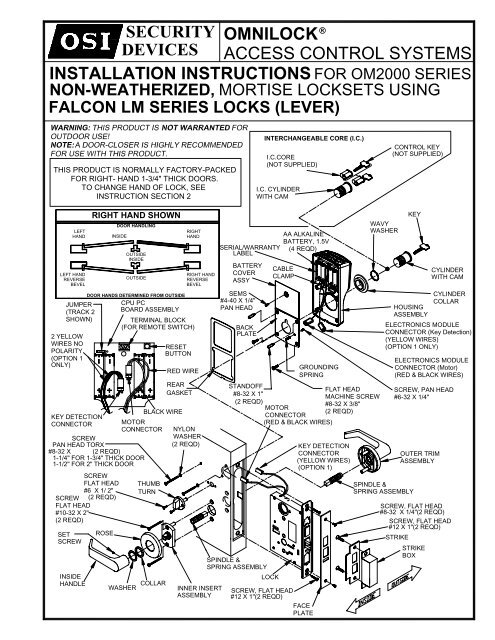
INSTALLATION INSTRUCTIONS FOR OM2000 SERIES<br />
NON-WEATHERIZED, MORTISE LOCKSETS USING<br />
FALCON LM SERIES LOCKS (LEVER)<br />
THIS PRODUCT IS NORMALLY FACTORY-PACKED<br />
FOR RIGHT- HAND 1-3/4" THICK DOORS.<br />
TO CHANGE HAND OF LOCK, SEE<br />
INSTRUCTION SECTION 2<br />
INTERCHANGEABLE CORE (I.C.)<br />
I.C.CORE<br />
(NOT SUPPLIED)<br />
I.C. CYLINDER<br />
WITH CAM<br />
CONTROL KEY<br />
(NOT SUPPLIED)<br />
LEFT<br />
HAND<br />
LEFT HAND<br />
REVERSE<br />
BEVEL<br />
JUMPER<br />
(TRACK 2<br />
SHOWN)<br />
2 YELLOW<br />
WIRES NO<br />
POLARITY<br />
(OPTION 1<br />
ONLY)<br />
SCREW<br />
FLAT HEAD<br />
#6 X 1/ 2"<br />
SCREW (2 REQD)<br />
FLAT HEAD<br />
#10-32 X 2"<br />
(2 REQD)<br />
SET<br />
SCREW<br />
INSIDE<br />
HANDLE<br />
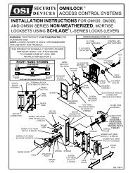
RIGHT HAND SHOWN<br />
ROSE<br />
DOOR HANDLING<br />
INSIDE<br />
OUTSIDE<br />
INSIDE<br />
OUTSIDE<br />
DOOR HANDS DETERMINED FROM OUTSIDE<br />
CPU PC<br />
BOARD ASSEMBLY<br />
TERMINAL BLOCK<br />
(FOR REMOTE SWITCH)<br />
BLACK WIRE<br />
KEY DETECTION<br />
CONNECTOR MOTOR<br />
CONNECTOR NYLON<br />
SCREW<br />
WASHER<br />
PAN HEAD TORX<br />
(2 REQD)<br />
#8-32 X (2 REQD)<br />
1-1/4" FOR 1-3/4" THICK DOOR<br />
1-1/2" FOR 2" THICK DOOR<br />
WASHER<br />
THUMB<br />
TURN<br />
COLLAR<br />
RESET<br />
BUTTON<br />
RED WIRE<br />
REAR<br />
GASKET<br />
RIGHT<br />
HAND<br />
RIGHT HAND<br />
REVERSE<br />
BEVEL<br />
INNER INSERT<br />
ASSEMBLY<br />
SERIAL/WARRANTY<br />
LABEL<br />
BATTERY<br />
COVER<br />
ASSY<br />
SEMS<br />
#4-40 X 1/4"<br />
PAN HEAD<br />
BACK<br />
PLATE<br />
STANDOFF<br />
FLAT HEAD<br />
#8-32 X 1"<br />
MACHINE SCREW<br />
(2 REQD)<br />
#8-32 X 3/8"<br />
MOTOR<br />
(2 REQD)<br />
CONNECTOR<br />
(RED & BLACK WIRES)<br />
SPINDLE &<br />
SPRING ASSEMBLY<br />
LOCK<br />
AA ALKALINE<br />
BATTERY, 1.5V<br />
(4 REQD)<br />
CABLE<br />
CLAMP<br />
SCREW, FLAT HEAD<br />
#12 X 1"(2 REQD)<br />
FACE<br />
PLATE<br />
GROUNDING<br />
SPRING<br />
KEY DETECTION<br />
CONNECTOR<br />
(YELLOW WIRES)<br />
(OPTION 1)<br />
WAVY<br />
WASHER<br />
HOUSING<br />
ASSEMBLY<br />
SPINDLE &<br />
SPRING ASSEMBLY<br />
ELECTRONICS MODULE<br />
CONNECTOR (Key Detection)<br />
(YELLOW WIRES)<br />
(OPTION 1 ONLY)<br />
ELECTRONICS MODULE<br />
CONNECTOR (Motor)<br />
(RED & BLACK WIRES)<br />
SCREW, PAN HEAD<br />
#6-32 X 1/4"<br />
SCREW, FLAT HEAD<br />
#8-32 X 1/4"(2 REQD)<br />
SCREW, FLAT HEAD<br />
#12 X 1"(2 REQD)<br />
STRIKE<br />
KEY<br />
OUTER TRIM<br />
ASSEMBLY<br />
STRIKE<br />
BOX<br />
CYLINDER<br />
WITH CAM<br />
CYLINDER<br />
COLLAR
a. To verify proper operation of the OMNILOCK System, connect the Motor Connector to the Electronics Module Connector<br />
so that the Red Wires are aligned. If Option 1 is installed, connect the Option 1 Connector (Yellow wires) to the<br />
Electronics Module Connector (Yellow wires), there is no polarity.<br />
b.<br />
Verify proper Keypad operation of the System by entering the Default<br />
Master ID 1234 at the Keypad. The System will flash green once and<br />
unlock, then, during the open delay it will flash green five (5) times. It<br />
will then flash red and lock.<br />
c. Verify proper operation of the Magnetic Card Reader. A Label on the<br />
Battery Cover indicates the magnetic card track, Track 2 or Track 3,<br />
that the Lockset is set to read. Select the corresponding Default<br />
Master ID Card, insert and remove it with the magnetic stripe on the<br />
card aligned with the "V" mark by the card slot. The lights will flash<br />
as in the previous step.<br />
LABEL<br />
d. While unlocked, check for proper operation of the Lockset.<br />
e. If Option 1 is installed, verify proper operation of the Key Detection Indicator.<br />
f.<br />
1.<br />
Install the Key Cylinder into the Lock so that the cam on the end of the Cylinder is approximately centered<br />
in the Lock and the keyway is at the bottom.<br />
2. Tighten the Cylinder Retaining Screw to keep the the Cylinder from turning.<br />
3. Insert the Key into the Key Cylinder and rotate the Key to operate the Latch Bolt. The green light will flash.<br />
If the Lock malfunctions, remove the Battery Cover and check for proper orientation and seating of the Batteries, the<br />
Motor Connector and the Key Detection Connector (Option 1). Check that the Track Selection Jumper is in the desired<br />
position. Also ensure that the wires are not pinched. Reset the electronics by pressing and holding the Reset Button<br />
on the circuit board for approximately three (3) seconds, until the light flashes green. The Lockset will go through a<br />
self test and flash green five (5) times. Replace the Battery Cover. Now repeat the verification process.<br />
g. After verifying proper operation, if your system requires use of the other magnetic track, proceed as follows, otherwise<br />
go to Step h:<br />
1. Remove the Battery Cover Retaining Screw and the Battery Cover.<br />
2. Move the Track Selection Jumper on the upper left corner of the circuit board to the desired track position.<br />
TRACK 2 SETTING<br />
TRACK 3 SETTING<br />
h.<br />
3. Mark the Label on the Battery Cover to indicate the selected track.<br />
4. Replace the Battery Cover and secure with the Screw.<br />
5.<br />
Insert and remove the corresponding Default Master ID Card. The lights will flash green once and unlock,<br />
then, during the Open DelayTime it will flash green five (5) times. It will then flash red and lock.<br />
If the verification process was successful, disconnect the Motor Connector. If Option 1 is installed, disconnect the<br />
Option 1 Connector and remove the Key Cylinder from the Lock.
2-1<br />
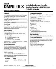
This section is only required if the lock hand, as received , does not meet your requirements. The Lock is normally<br />
preset for a right hand door. Verify the hand of the Lock and if required, Change the hand of the Lock as follows,<br />
after checking per Section 1.<br />
NOTE: If the Lock has a Dead Bolt, it must be in the retracted position when reversing hand.<br />
a. REMOVE COVER<br />
1. Remove the four Cover Retaining Screws and slowly remove the Cover from the Case.<br />
b. REVERSE LATCH BOLT ASSEMBLY<br />
1. Lift out the Cylinder Retract Lever, if included.<br />
2. Lift out the Upper Retract Arm, if included.<br />
3. Compress the Latch Bolt Spring toward the Face Plate to clear the Latch Bolt Guide Seat. Lift out and invert the<br />
Latch Bolt Assembly. Place the Latch Bolt Spring into the Latch Bolt Guide Seat.<br />
FACE PLATE<br />
NOTE: Lower Retract Arm (below the Upper Retract Arm) must be between the<br />
Latch Bolt Foot and the Latch Bolt Guide.<br />
CYLINDER<br />
RETRACT<br />
c. REVERSE HUBS<br />
LEVER<br />
1. To reverse, pull the Coupling toward the rear of the Case.<br />
2. Lift out both Hubs together, invert as an assembly and replace. FOOT<br />
3. Ease the Coupling back against the Hubs.<br />
UPPER<br />
RETRACT<br />
d. REASSEMBLE RETRACT ARM AND LEVER<br />
ARM<br />
1. Replace the Upper Retract Arm so that the Arm fits into the space<br />
between the Latch Bolt Foot and the Coupling.<br />
COUPLING<br />
2. Replace the Cylinder Retract Lever so that it straddles the Dead Bolt Pin.<br />
HUB<br />
LATCH BOLT<br />
SPRING<br />
3. Replace the Cover guiding the "T" Turn Hub into the Cover hole. Depress the Latch Bolt to clear the Foot.<br />
NOTE: A Phillips head screw driver inserted through the Cover into the "T" Turn Hub will retain the Hub and Cylinder<br />
Retract Lever in proper location while replacing the Cover.<br />
e. REPLACE THE COVER RETAINING SCREWS.<br />
f. REVERSE DEADLOCKING BAR<br />
CYLINDER<br />
1. Remove the Face Plate. Remove the Deadlocking Bar, RETRACT<br />
reverse it and replace it back into the Assembly.<br />
LEVER<br />
(Push against Blocker Assy to allow Deadlocking Bar<br />
to be easily inserted)<br />
DEAD BOLT PIN<br />
"T" TURN<br />
HUB<br />
2. ReplacetheFacePlate.<br />
FOOT<br />
UPPER<br />
RETRACT<br />
ARM<br />
BLOCKER<br />
ASSY<br />
DEADLOCKING<br />
BAR<br />
LOCK FRONT<br />
NOTE: The Concave Face of the Deadlocking Bar must be on the same<br />
side of the Door as the Beveled Face on the Latch Bolt. If this<br />
condition is not met, the Latch Bolt will be blocked from being<br />
able to be depressed as it comes into contact with the Strike.<br />
LOCK FRONT<br />
SCREW
2-2<br />
REVERSE HANDLE RETURN SPRING<br />
Example shown is a right hand being changed to<br />
a left hand. Reverse the sequence to change from<br />
alefthandtoarighthand.<br />
Note: Inside Trim is always opposite the<br />
Outside Trim<br />
LH/LHR<br />
RH/RHR<br />
a. Holding the Lever as shown, bend the Tab of the<br />
Lock Washer back flat. Remove the Nut.<br />
LEVER/HANDLE VIEW FROM OUTSIDE<br />
b. Holding the Lever securely, rotate the Rose Assembly clockwise slightly and remove the Plate and Lock Washer.<br />
c. Using caution, allow the Rose Assembly to rotate<br />
counterclockwise to relieve Spring Tension.<br />
d. Remove the Spring and reinstall with the Spring<br />
Hook on the opposite side of the Post.<br />
e. Holding the Lever securely, rotate the Rose Assembly<br />
counterclockwise slightly past 90°.<br />
f.<br />
ReinstallthePlatewiththe"L"sideupandin<br />
linewiththe"L"ontheRoseAssembly.<br />
g. Reinstall the Lock Washer and the Nut. Tighten the Nut and then back off slightly until the Rose Assy rotates<br />
freely under the Plate. Bend up one Tab of the Lock Washer against the Nut.
3-1<br />
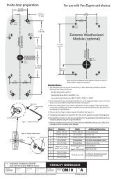
a. Draw a horizontal centerline on both sides and edge of the Door<br />
at the desired Knob Center Height (Fig. 1).<br />
NOTE: If the Frame has already been prepared for a Falcon Strike.<br />
Install the Strike and use the Strike Lip as a reference to locate<br />
the horizontal centerline position. Mark the Door 3/16" below the<br />
bottom of the Strike Lip as illustrated in Fig.2 and draw horizontal<br />
centerlines on the Door at this position as illustrated in Fig.1.<br />
HORIZONTAL CENTERLINE<br />
LOCATING POSITION OF<br />
WHEN FRAME HAS BEEN<br />
PREPARED FOR STRIKE<br />
FIG 1<br />
b.<br />
c.<br />
Using the Backset Locator furnished, mark two points on each side<br />
of the Door, above and below the horizontal line . (Fig.3). Draw a<br />
vertical line through the two points on each side of the Door.<br />
Separate the Door Edge Template from the Door Surface Template.<br />
Position the correct side of the Door Surface Template on the outside<br />
face of the Door, aligning the Locator points with the horizontal and<br />
vertical lines drawn on the Door as illustrated in Fig. 4<br />
3/16"<br />
CAUTION:<br />
Spot only those holes required for the Lockset being<br />
installed, and mark the Strike Lip position on the Frame.<br />
FIG 2<br />
d.<br />
Using the opposite side of the Template, position on the inside face<br />
of the Door aligning locator points with the horizontal and vertical<br />
lines drawn on the Door and spot the required holes.<br />
e. Center the Door Edge portion of the Template on the Door edge and<br />
align the horizontal Locator points with the horizontal line drawn on<br />
the Door. Mark the top and bottom points of the Case Mortise and the<br />
Face Plate top reference as illustrated in Fig.5.<br />
LOCATING<br />
VERTICAL CL<br />
FIG 3<br />
MARK FACE<br />
PLATE TOP<br />
REFERENCE<br />
MARK STRIKE LIP<br />
POSITION ON FRAME.<br />
NOTE:<br />
BOTTOMOFLIPIS3/16"<br />
ABOVE HORIZONTAL CL<br />
FIG 5<br />
FIG 4<br />
3-2<br />
a.<br />
Mortise the Door edge for the Lock Case to the dimensions shown on the<br />
Template. Insert the Lock (with Face Plate) in Mortise.<br />
ALIGN WITH<br />
REFERENCE<br />
MARK<br />
CAUTION: Do not pinch the Motor Wires.<br />
b. Align the top of the Face Plate with the reference mark and scribe the Face<br />
Plate outline as illustrated in Fig.6. Mortise to the front thickness.<br />
c. Drill the required side holes through the outside and inside faces of the Door.<br />
SCRIBE<br />
FACE<br />
OUTLINE<br />
FIG 6<br />
CAUTION:<br />
Drill the holes only halfway through the Door from each side.
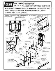
4-1<br />
a. Remove the Face Plate and guide the Connector(s) and the Lock into Mortise<br />
so that the Cable(s) passes through the slot above the Cylinder hole and the<br />
Lock is seated in the Mortise.<br />
CAUTION: Do not pinch the Cable(s).<br />
CONNECTOR<br />
(OPTION 1 ONLY)<br />
(YELLOW WIRES)<br />
b. Mark the hole location for the Case Attachment Screws and remove the Lock<br />
from the Mortise. For Wood Doors, drill 1/8" Dia. pilot holes for Case Attachment<br />
Screws, and counter drill the holes 7/32" dia. x 3/16" deep for Combination Screws.<br />
For Metal Doors, drill 3/16" dia. holes. Adjust the Front Bevel as required by<br />
loosening the Screws at the top and bottom of the Case, set the Bevel and securely<br />
re-tighten the Screws. Install the Lock.<br />
CASE<br />
ATTACHMENT<br />
SCREWS<br />
MOTOR CABLE<br />
CONNECTOR<br />
(RED AND<br />
BLACK WIRES)<br />
4-2<br />
ATTACH THE TRIM<br />
a. Insert the Inner and Outer Spindle and Spring Assemblies<br />
into the Lock Hubs. Place the Outer Trim Assembly over the<br />
Outer Spindle and Spring Assembly.<br />
SPINDLE &<br />
SPRING ASSY<br />
OUTER TRIM<br />
ASSEMBLY<br />
b. Place the Inner Insert Assembly over the Inner Spindle SCREW<br />
10-32 X 2"<br />
and Spring Assembly. Put the Screws through the Insert<br />
and thread into the Posts of the Outer Trim until tight.<br />
THREADED POST<br />
SPINDLE &<br />
SPRING ASSY<br />
OUTSIDE<br />
c. Place the Rose over the Insert, thread on the Collar and<br />
tighten with the Spanner Wrench. Place the Washer over<br />
the Outside of the Shank. Put the Inside Handle on the<br />
Shank , and as you are pressing toward the Door, tighten<br />
theSetScrewintheHandleuntiltight.<br />
INNER INSERT<br />
ASSY<br />
INSIDE<br />
d. Install the Thumb Turn if required.<br />
INSERT<br />
ROSE<br />
THUMB<br />
TURN<br />
SET SCREW<br />
(INSTALLED)<br />
COLLAR<br />
INSIDE<br />
HANDLE<br />
WASHER<br />
SHANK<br />
INSIDE<br />
OUTSIDE
4-3<br />
INSTALL THE ELECTRONICS MODULE<br />
a. Guide the the Connector(s) through the front hole in the Module,<br />
andplacetheModuleagainsttheDoorsothattheStandoffsand<br />
the Grounding Spring enter their respective holes.<br />
MOUNTING<br />
SCREW (2 REQ'D)<br />
b. Install the mounting Screws and Washers finger tight.<br />
c. Connect the Motor Connector (Red and Black Wires) to the<br />
Module Connector so that the Wire colors match. If installed,<br />
connect the Option 1 Connector to the Module Connector<br />
(Yellow Wires).<br />
d. Insert the Cables and the Connectors into the Module so that<br />
they are clear of the Cylinder Hole.<br />
WASHER (2 REQ'D)<br />
4-4<br />
INSTALL THE CYLINDER<br />
a. Insert the Cylinder with the Wavy Washer and Collar<br />
into the Module and partially screw it into the Lock.<br />
b. Tighten the Module Mounting Screws and then tighten<br />
the Cylinder until it is snug with the keyway at the bottom.<br />
c. Tighten the Cylinder Retaining Screw and install<br />
theFacePlate.<br />
COLLAR<br />
d. Repeat Step 1b through 1d, and step 1e3<br />
if Option 1 is installed, to verify operation.<br />
WAVY<br />
WASHER<br />
CYLINDER<br />
CYLINDER<br />
RETAINING<br />
SCREW<br />
FACE PLATE
a. Draw a vertical line on the Door Frame 1/2 the Door thickness from the Door Stop.<br />
CAUTION:<br />
Allow for paint buildup or weather stripping if required.<br />
b. Select the Strike with the proper hand condition and align the bottom edge of the Strike Lip with the mark on the<br />
Door Frame and align the center of the mounting holes in the Strike with the vertical line on the frame. Using the<br />
Strike as a template, mark the Door Frame.<br />
c. Using the Strike Box as a template, mark the Door Frame.<br />
d. MortisetheFrametoaccepttheStrikeandStrikeBox.<br />
e. Install the Strike Box and the Strike and secure with the Screws.<br />
STRIKE BOX<br />
SCREW<br />
#12 X 1<br />
ALIGNMENT<br />
MARKS<br />
STRIKE<br />
NOTE:<br />
For wood doors, drill 1/8" dia. pilot holes and counter drill the holes 7/32" dia. x 3/16" deep for combination<br />
Screws. For metal doors, drill 3/16" dia. holes.<br />
To avoid unauthorized <strong>access</strong>, it is important to program a new Master ID.<br />
Refer to the OMNILOCK OM2000 Lockset User Guide and to the OMNILOCK OM2000 Software User Guide<br />
for programming <strong>instructions</strong>. If the Lockset has been installed on a door before the required programming<br />
information is available, the Access Level may be set to unlocked as follows:<br />
1. Enter the Default Manager ID 2222 at the Keypad, the green light will flash.<br />
2. Press 2, the green light will flash.<br />
3. Press and hold the CL key until the green light flashes four times.<br />
(The light will flash once when the CL key is first pressed, continue to hold the key until the light flashes<br />
three more times.)<br />
4. The Lock will remain in the Unlocked mode.<br />
INSTALLER NOTE:<br />
Leave these <strong>instructions</strong> with the user.<br />
Copyright ©2000 OSI Security Devices Inc. All Rights Reserved.<br />
OMNILOCK is a Registered Trademark of OSI Security Devices Inc.<br />
SECURITY<br />
DEVICES<br />
FALCON is a Trademark of Falcon Lock Co.<br />
(Website: www.osisecurity.com)<br />
11156 REV. A<br />
1580 JAYKEN WAY<br />
CHULA VISTA, CALIFORNIA 91911<br />
619.628.1000 FAX 619.628.1001