arrow - OSI Security Devices
arrow - OSI Security Devices
arrow - OSI Security Devices

You also want an ePaper? Increase the reach of your titles
YUMPU automatically turns print PDFs into web optimized ePapers that Google loves.
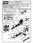
SECURITY<br />
DEVICES<br />
OMNILOCK ®<br />
ACCESS CONTROL SYSTEMS<br />
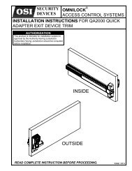
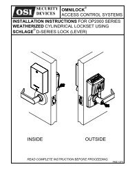
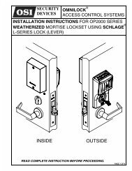
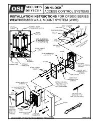
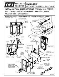
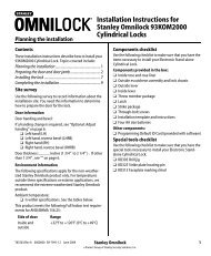
INSTALLATION INSTRUCTIONS FOR OM100, OM300,<br />
AND OM500 SERIES NON- WEATHERIZED, CYLINDRICAL<br />
LOCKSETS USING ARROW TM Q-SERIES LOCKS (LEVER)<br />
WARNING: THIS PRODUCT IS NOT WARRANTED FOR<br />
OUTDOORS USE!<br />
NOTE: A DOOR-CLOSER IS HIGHLY RECOMMENDED<br />
FOR USE WITH THIS PRODUCT.<br />
THIS PRODUCT IS NORMALLY FACTORY-PACKED<br />
FOR RIGHT-HAND 1-3/4” THICK DOORS.<br />
TO CHANGE HAND OF LOCK, SEE<br />
INSTRUCTION SECTION 3<br />
DO NOT USE ON DOORS THICKER THAN 1-3/4”<br />
LEFT<br />
HAND<br />
RIGHT HAND SHOWN<br />
DOOR HANDLING<br />
INSIDE<br />
OUTSIDE<br />
INSIDE<br />
RIGHT<br />
HAND<br />
AA ALKALINE<br />
BATTERY, 1.5V<br />
(4-REQD)<br />
INTERCHANGEABLE CORE (I.C.)<br />
I.C. TAIL I.C. CORE<br />
PIECE<br />
I.C.<br />
OUTSIDE<br />
LEVER<br />
RETAINER<br />
OUTSIDE<br />
LEVER<br />
CONTROL<br />
KEY<br />
KEY<br />
LEFT HAND<br />
REVERSE<br />
BEVEL<br />
OUTSIDE<br />
DOOR HAND DETERMINED FROM OUTSIDE<br />
RIGHT HAND<br />
REVERSE<br />
BEVEL<br />
OUTSIDE ROSE<br />
INSERT ASSEMBLY<br />
MOTOR<br />
CONNECTOR<br />
CYLINDER<br />
HOUSING PUSH<br />
ASSEMBLY PIN<br />
(PROVIDED)<br />
CPU PC<br />
BOARD<br />
ASSEMBLY<br />
TERMINAL BLOCK<br />
(FOR REMOTE SWITCH)<br />
RESET<br />
BUTTON<br />
RED<br />
WIRE<br />
SPINDLE<br />
FLEXIBLE<br />
ADAPTER<br />
LOCK<br />
BODY<br />
PLATE<br />
NUT<br />
GASKET<br />
ROSE<br />
SEMS<br />
#4-40 X .25<br />
PAN HEAD<br />
BATTERY<br />
COVER<br />
ASSEMBLY<br />
MOTOR<br />
CONNECTOR<br />
BLACK<br />
WIRE<br />
SCREW<br />
PAN HEAD<br />
#6 X 3/4 “<br />
(2-REQD)<br />
BACK<br />
PLATE<br />
INSIDE ROSE<br />
INSERT ASSY<br />
SCREW<br />
FLAT HEAD<br />
10-32 X 2-1/4”<br />
(2-REQD)<br />
FLEXIBLE<br />
ADAPTER<br />
LATCH<br />
UNIT<br />
STRIKE<br />
FLAT HEAD<br />
MACHINE<br />
SCREW<br />
#8-32 X .375 LG<br />
(4-REQD)<br />
INSIDE LEVER<br />
WITH RETAINER<br />
ROSE<br />
NUT<br />
PLATE<br />
SCREW<br />
FLAT HEAD<br />
#8 X 3/4”<br />
(2-REQD)<br />
SCREW<br />
FLAT HEAD<br />
#12 X 3/4”<br />
(2-REQD)<br />
STRIKE BOX<br />
PG. 1 OF 4
SECTION 1: INSTALL THE KEY CYLINDER AND OUTSIDE LEVER<br />
CYLINDER<br />
1-1 If the Lever requires a standard Key cylinder, proceed as follows:<br />
a. Using standard Pliers, pull out the Outside Retainer.<br />
b. Insert the Cylinder into the Outside Lever.<br />
RETAINER<br />
c. Secure the Cylinder by pressing the retainer until it is flush with the shelf.<br />
d. Slide the Outside Lever onto the Outside spindle as far as possible. Insert the Key and turn it 45°<br />
clockwise. Push the Lever again, until the Lever Catch is engaged, securing the Lever.<br />
1-2 If the Lever requires an Interchangeable core (I.C.) proceed<br />
as follows:<br />
a. Ensure that the retaining Ring and Anti-pick Plate are orientated as shown.<br />
b. Push the I.C. Lever onto the Outside Spindle until the Lever Catch is engaged.<br />
c. Install the Interchangeable Core per Section 8.<br />
OUTSIDE SPINDLE<br />
END VIEW<br />
LEVER<br />
CATCH<br />
OUTSIDE<br />
SPINDLE<br />
SHELF<br />
OUTSIDE<br />
LEVER<br />
RETAINING<br />
RING<br />
ANTI-PICK<br />
PLATE<br />
SECTION 2: CHECK OPERATION<br />
a. Verify proper operation of the System by entering the Default Master Code 5011234. The System will flash three times to<br />
indicate the Battery level and unlock. It will remain unlocked for approximately 5 seconds before flashing red and relocking.<br />
b. While unlocked, check for proper operation of the Lock.<br />
c. Verify communication with the WP4000 Printer.<br />
1. Turn on the Printer and Position it over the Keypad so that the Infrared Port of the<br />
Printer is aligned over the Infrared Port of the System.<br />
2. Enter the Default Master Code 5011234 at the Keyboard and then enter 99.<br />
3. The Printer will print some System data and then present a menu of choices.<br />
4. Enter 0 (END) at the Keypad. The System will flash red and re-locked.<br />
d. If the system malfunctions, remove the Battery Cover and check for proper orientation and seating of<br />
the Batteries and Motor Connector. Also ensure that the wires are not pinched. Reset the electronics<br />
by pressing and holding the Reset Button on the circuit board until the light on the Keypad flashes<br />
green, approximately three to five seconds. The System will go through a self-test and flash green 5<br />
times. Any red flash indicates an electronics or motor problem. If all flashes are green, repeat Steps<br />
a, b and c.<br />
<strong>OSI</strong> SECURITY<br />
+12645645<br />
-125<br />
=98765<br />
SECTION 3: ADJUST THE LOCK HAND<br />
3-1 This section is only required if the lock hand does not meet your requirements. The Lockset is normally preset for a right<br />
hand door. Verify the handing of the Lock and, if required, change the hand of the Lock as follows after checking per<br />
Section 2.<br />
a. Carefully release the Gasket from the edge of the Housing Assembly using<br />
your fingers, and remove the Gasket. Remove the Screw from the Battery<br />
Cover and remove the Cover. Disconnect the Motor Connector from the<br />
CPU Board.<br />
b. Remove four Flat Head Screws from the Back Plate and remove the Back<br />
Plate.<br />
BATTERY<br />
COVER<br />
SEMS<br />
#4-40X.25<br />
PAN HEAD<br />
HOUSING<br />
ASSEMBLY<br />
LOCKSET<br />
ASSEMBLY<br />
3-2<br />
a. Rotate the lockset to left-hand orientation.<br />
b. Route the Wires close to the center of the Lockset and to the upper center of the Outside<br />
Rose.<br />
c. Align Wires into the notch of the Back Plate under the Translucent Label. Install the<br />
Back Plate and four Screws into the Housing Assembly.<br />
WARNING: Ensure that the Wires are not pinched before and after tightening the<br />
Screws.<br />
d. Install the Motor Connector with the Black Wire to the left (see label on CPU Board).<br />
Arrange the excess wire between the Battery Holders.<br />
e. Install the Battery Cover and secure it with the Screw.<br />
f. Install the Gasket so that it seats inside the edge of the Housing.<br />
g. Repeat Section 2.<br />
PG. 2 OF 4<br />
GASKET<br />
GASKET<br />
TERMINAL BLOCK<br />
CPU PC<br />
BOARD<br />
BATTERY<br />
COVER<br />
SEMS<br />
#4-40X.25<br />
PAN HEAD<br />
BACK PLATE<br />
RESET<br />
RED<br />
WIRE<br />
BLACK<br />
WIRE<br />
MOTOR<br />
CONNECTOR<br />
HOUSING<br />
ASSEMBLY<br />
SCREW<br />
(4REQD)
SECTION 4: PREPARE THE DOOR<br />
4-1 MARK HOLE LOCATIONS<br />
a. Mark a height line on the door faces and edge (suggested height<br />
is 38” from the floor).<br />
b. Line up the Template at the correct marking for the Door Bevel<br />
(high or low bevel, or flat). Position the centerline of the<br />
Template on the height line. Note whether the holes should be<br />
marked on the Inside, outside, or both sides of the door. Mark<br />
the Centers as required for the holes.<br />
c. Mark the center of the Door thickness on the height line.<br />
HIGH<br />
BEVEL<br />
TEMPLATE<br />
DOOR<br />
DOOR<br />
LOW<br />
BEVEL<br />
4-2 DRILL HOLES<br />
a. Bore the 2-1/8” hole and the 7/16” holes half way through the door from<br />
both sides to avoid splintering.<br />
b. Add the notches to both sides of the door.<br />
c. Bore a 1” hole into the door edge center on the height line, Use the<br />
Latch Unit Faceplate as a pattern and mark the door edge. Mortise the<br />
door edge so that the front of the faceplate will be flush with the door<br />
edge. Insert the Latch Unit into the 1” hole, making certain that the Latch<br />
Bolt Bevel faces the direction of the closing Door.<br />
d. Secure the Latch Unit with the Screws supplied.<br />
HOLE<br />
MOUNTING<br />
SCREWS<br />
LATCH UNIT<br />
NOTCH<br />
(4-REQD)<br />
2-1/8” HOLE<br />
7/16” HOLE<br />
(2-REQD)<br />
SECTION 5: INSTALL THE SYSTEM ON THE DOOR<br />
5-1 NOTE: DO NOT USE ON A DOOR THICKER THAN 1-3/4” UNLESS THE SYSTEM IS<br />
SPECIFICALLY DESIGNED FOR A THICKER DOOR.<br />
SHORT MARK<br />
LOCATED<br />
ON PLATE<br />
a. The Lockset is normally preset for a 1-3/4” Door. For 1-3/4” Door the “short mark” on<br />
the Lockset Plate is aligned with the edge of the Lock Body.<br />
b. For a 1-3/4” door with a Push Plate (.050” max.) turn the Nut counterclockwise until the<br />
short mark is the thickness of the Push Plate from the edge of the Lock Body. Adjust the<br />
Outside Nut with a pair of n<strong>arrow</strong> jaw Pliers, a small Screwdriver, a Scribe, or your Fingers.<br />
c. If a Remote Switch is to be used to operate the System, see Section 10.<br />
LOCK<br />
BODY<br />
5-2 Install the System on the outside of the door. The Lock Body must<br />
engage the Latch Unit Prongs as shown. The Lock Body Retractor<br />
must engage the Latch Unit Tail piece.<br />
LOCK<br />
BODY<br />
LATCH UNIT<br />
PRONGS<br />
5-3<br />
Install the Plate and Nut on the<br />
inside, and secure the Plate with<br />
the Screws.<br />
PLATE<br />
NUT<br />
SCREW<br />
PAN HEAD<br />
#6 X 3/4"<br />
(2-REQD)<br />
LOCK BODY<br />
RETRACTOR<br />
LATCH UNIT<br />
TAIL PIECE<br />
NUT<br />
5-4<br />
a. Slide the Rose Insert onto the Spindle and secure the Rose Insert with the Screws.<br />
b. Slide the Flexible Adapter over the Spindle depressing the Lever Catch. Make certain that<br />
the Tab of the Flexible Adapter is located opposite to the Lever Catch and projections of<br />
the Flexible Adapter line up with matching depressions of the Rose Insert Assembly.<br />
c. Place the Inside Rose onto the Rose Insert aligning the dimples with the recesses in<br />
the Rose Insert and turn clockwise to secure it.<br />
d. Slide the Inside Lever on the Inside Spindle. Make certain that the<br />
Lever Catch on the Spindle is engaged with the Lever.<br />
e. Repeat Section 2 to verify proper operation.<br />
FLEXIBLE ADAPTER<br />
INSIDE LEVER<br />
Binding or rough operation is an indication of improper installation.<br />
INSIDE<br />
ROSE<br />
SCREW<br />
FLAT HEAD<br />
#6 X 3/4"<br />
(2-REQD) INSIDE<br />
SPINDLE<br />
ROSE INSERT<br />
PG. 3 OF 4
OMNILOCK<br />
SECTION 6: INSTALL THE STRIKE<br />
a. Mark the Location of the Latch Bolt on the Door Frame.<br />
b. Center the Strike over the Latch Bolt Mark and, using the Strike as a template, mark the Frame.<br />
c. Using the Strike Box as a template, mark the Frame.<br />
d. Mortise the Frame to accept the Strike and Strike Box.<br />
e. Install the Strike Box and the Strike and secure with the Screws.<br />
SCREW<br />
#12 X 3/4"<br />
(2-REQD)<br />
STRIKE BOX<br />
STRIKE<br />
SECTION 7: PROGRAM THE LOCK<br />
IMPORTANT: To avoid unauthorized access, it is important to program a new Master Code.<br />
For Programming instructions refer to the Quick Reference Guide shipped with this product or to the OMNILOCK User<br />
Guide which may be ordered by calling Customer Service at 619-628-1000 or it may be downloaded from our website<br />
http://www.omnilock.com/files/om135man.pdf<br />
SECTION 8: INTERCHANGEABLE CORE<br />
8-1 INTERCHANGEABLE (I.C.) CORE AND TAIL<br />
PIECE MEMBERS INSTRUCTIONS<br />
Be certain to use the correct Tail<br />
6-PIN<br />
Piece member with the Core. Six- CORE<br />
Pin Cores use only the “L6” Tail<br />
Piece member and Seven-Pin<br />
Cores use only the “L7” Tail<br />
Piece member.<br />
SECTION 9: REMOVAL OF LEVERS<br />
SECTION 10: REMOTE SWITCH<br />
SECURITY<br />
DEVICES<br />
L6 TAIL PIECE<br />
MEMBER (6-PIN)<br />
7-PIN<br />
CORE<br />
L7 TAIL PIECE<br />
MEMBER (7-PIN)<br />
8-2 INTERCHANGEABLE LEVER WITH<br />
INTERCHANGEABLE (I.C.) CORE<br />
Insert the I.C. Tail Piece into the I.C. CORE<br />
I.C. Core. Insert the Control Key<br />
into the I.C. Core and turn it 15°<br />
clockwise. Insert the Core into<br />
the I.C. Outside Lever and turn<br />
the Control Key 15° counterclockwise<br />
to lock the Core in the PIECE<br />
I.C. TAIL<br />
Lever.<br />
9-1 REMOVING OUTSIDE LEVER WITH STANDARD 9-2 REMOVING OUTSIDE LEVER WITH<br />
CYLINDER<br />
KEY INTERCHANGEABLE (I.C.) CORE OUTSIDE SPINDLE<br />
a. Insert the Key into the Cylinder<br />
END VIEW<br />
and turn 45° clockwise.<br />
LEVER<br />
CATCH<br />
b. Depress the Lever Catch through<br />
the hole in the Outside Lever by<br />
OUTSIDE<br />
using the Push Pin provided or LEVER<br />
another suitable tool.<br />
c. Slide the Outside Lever from the Spindle.<br />
9-3 REMOVING THE INSIDE LEVER<br />
a. Depress the Lever Catch through<br />
the hole in the Inside Lever by<br />
using the Push Pin provided or<br />
another suitable tool.<br />
b. Slide the Inside Lever from the<br />
Spindle.<br />
PUSH PIN (PROVIDED)<br />
PUSH PIN<br />
(PROVIDED)<br />
INSIDE<br />
LEVER<br />
a. Insert the control Key into the I.C.<br />
Core and rotate it 15° clockwise.<br />
Pull on the Key to remove the I.C.<br />
Core. Be sure that the I.C. Tail<br />
Piece is removed with the Core.<br />
b. Ensure that the Retaining Ring and the<br />
Anti-Pick Plate are aligned with the<br />
Lever Catch as shown.<br />
c. Insert an awl or a small screwdriver through<br />
the I.C. Outside Lever and into the slot in the<br />
Anti-Pick Plate. Depress the Lever Catch<br />
toward the Door Hinge and slide the I.C.<br />
Outside Lever from the Spindle.<br />
a. Remote operation of the System may be accomplished by a momentary Switch<br />
closure. This may be desirable for someone monitoring a protected entrance, such as a<br />
receptionist. Momentarily pressing the Switch will cause the System to go through a<br />
normal unlock and lock sequence. If the Switch is held closed, the open time will be<br />
extended.<br />
b. Connect a twisted pair of wires from the Terminal Block on the PC Board to a normally<br />
open momentary contact Switch. Plan the route for your wire and the access route<br />
through the door to the PC Board in the OMNILOCK Module. Plan for disconnecting<br />
the wires in the Lock area so that the System can be removed from the door to change<br />
the Batteries as required.<br />
CONTROL KEY<br />
I.C.<br />
OUTSIDE<br />
LEVER<br />
Copyright ©2001 <strong>OSI</strong> <strong>Security</strong> <strong>Devices</strong> Inc. All Rights Reserved<br />
OMNILOCK is a Registered Trademark of <strong>OSI</strong> <strong>Security</strong> <strong>Devices</strong> Inc. ARROW is a Trademark of Arrow Lock Co. 11517 REV A<br />
(Website: WWW.OMNILOCK.COM)<br />
PG. 4 OF 4<br />
OUTSIDE<br />
SPINDLE<br />
SWITCH<br />
TWISTED<br />
PAIR<br />
RETAINING<br />
RING<br />
ANTI-PICK<br />
PLATE<br />
1580 JAYKEN WAY<br />
CHULA VISTA, CALIFORNIA. 91911<br />
(619) 628-1000 FAX (619) 628-1001