Operating Manual - Whip Mix
Operating Manual - Whip Mix
Operating Manual - Whip Mix

You also want an ePaper? Increase the reach of your titles
YUMPU automatically turns print PDFs into web optimized ePapers that Google loves.
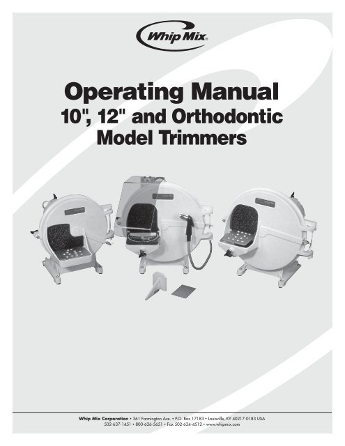
<strong>Operating</strong> <strong>Manual</strong><br />
10", 12" and Orthodontic<br />
Model Trimmers<br />
<strong>Whip</strong> <strong>Mix</strong> Corporation • 361 Farmington Ave. • P.O. Box 17183 • Louisville, KY 40217-0183 USA<br />
502-637-1451 • 800-626-5651 • Fax 502-634-4512 • www.whipmix.com
<strong>Operating</strong> <strong>Manual</strong> 10", 12" and Orthodontic Model Trimmers<br />
Installation<br />
Standard equipment packaged with the Model<br />
Trimmer includes:<br />
1 – Orthodontic Work Table or Regular Work Table<br />
1 – Coarse abrasive wheel installed<br />
1 – 24” length of drain hose installed<br />
1 – 30” length of plastic water hose installed<br />
1 – Package of 4 rubber feet, two long and two short<br />
<strong>Whip</strong> <strong>Mix</strong> Deluxe Model Trimmers include those items<br />
mentioned above and the following accessories:<br />
1 – Electric Water Valve installed<br />
1 – Water Spray Attachment installed<br />
1 – Splash Shield<br />
Remove the Model Trimmer from the shipping carton.<br />
It is a good idea to keep the shipping carton, should the<br />
model trimmer have to be moved or shipped. Select a<br />
location for the model trimmer that provides easy access<br />
for cleaning and maintenance. Electrical, water and drain<br />
hookups are required.<br />
Space required by each unit:<br />
10” Model Trimmer 14” W x 16” H x 15” D<br />
12” Model Trimmer 16” W x 17” H x 15” D<br />
Model Trimmers supplied without the electric water valve<br />
require the installation of a nearby manual on/off water<br />
valve. A 1⁄4” pipe fitting is provided on the end of the plastic<br />
water hose for connecting the water supply.<br />
NOTE: The valve provided on the water spray tube<br />
is for flow adjustment only and is not intended for use<br />
as an on/off valve.<br />
Several methods of mounting are available. The most<br />
common method is to drill holes through the countertop to<br />
bold the model trimmer in place. Rubber feet are provided<br />
as an alternative – use the two with long bolts in front and<br />
the two short ones in the back. A third possibility is to mount<br />
the model trimmer in the sediment tray (see accessories).<br />
Figure 1<br />
The orthodontic work table is readily adjustable, and the<br />
anodized parts dismantle easily for thorough cleaning. The<br />
following accessories are included with each orthodontic<br />
work table:<br />
Vertisquare – Constructed of low friction, durable plastic,<br />
the vertisquare is utilized to aid in the trimming of the model<br />
base. An adhesive foam rubber pad attached to the<br />
vertisquare absorbs shock, helps prevent breakage of teeth,<br />
and provides a safe buffer zone between the hands of the<br />
user and the model trimmer wheel. Additional facing pads<br />
may be ordered in a package of 3 (part no. 30217).<br />
Angleguide – The angleguide is constructed of the same<br />
special plastic as the vertisquare. This accessory helps<br />
position the model for trimming at the desired angle<br />
indicated by the degree plate of the work table.<br />
70mm Template – This device is used to accurately set the<br />
table angle, the degree plate reading and the vertisquare<br />
distance indicator.<br />
Plug the unit into a grounded receptacle having the<br />
same electrical characteristics as shown on the model<br />
trimmer data plate.<br />
The 24” length of drain hose can be placed in a nearby<br />
sink or directed into a drain pipe. For either installation,<br />
a plaster trap is recommended.<br />
Adjust angulation of the work table to the abrasive wheel.<br />
The 12” model trimmer provides a range of adjustment<br />
from 85° to 120° to the abrasive wheel. The locking nut<br />
can be tightened with a wrench to set permanently a<br />
particular angle.<br />
The two-position work table, standard on the 10” model<br />
trimmer, is factory set perpendicular to the abrasive wheel.<br />
One other setting is available to increase this angle.<br />
Figure 2
<strong>Operating</strong> <strong>Manual</strong> 10", 12" and Orthodontic Model Trimmers<br />
Calibrating the Orthodontic<br />
Work Table<br />
Work Table Angle Adjustment – Hold the 70mm template<br />
upright on the work table so the table is 90° (perpendicular)<br />
to the wheel. Tighten vertical adjustment knob (Fig. 3).<br />
Locking nut can be tightened with wrench for permanent<br />
installation. The vertisquare may also be used to hold the<br />
70mm template in the upright position.<br />
Degree Plate Adjustment – Loosen the 2 screws on the<br />
spring latch (A – Fig. 4). Place the 70mm template flat on<br />
the work table in front of the vertisquare and against the<br />
trimmer wheel. Rotate the degree plate until the vertisquare<br />
is parallel with the template. First, tighten the back screw on<br />
the spring latch, and then tighten the front screw. NOTE:<br />
The white indicator mark on the front of the work table is the<br />
approximate zero location.<br />
Vertisquare Calibration – With the 70mm template flat on<br />
the work table, loosen both screws on vertisquare pointer<br />
(B – Fig. 4) and position the pointer so that it is even with<br />
the 70mm line (C – Fig. 4).<br />
B<br />
Figure 3 Figure 4<br />
C A<br />
Operation<br />
The on/off switch is protected by a rubber cap – flip this<br />
switch to turn unit on. Turn on water supply and before<br />
each use; allow motor to run with water on for a minute to<br />
counteract vibration caused by water settling in the lower<br />
portion of the wheel.<br />
The amount of water spraying the wheel is regulated by<br />
adjusting the water valve. Water flow is excessive if water<br />
drips steadily from the top of the window. The water spray<br />
tube located inside the door has been factory set to spray<br />
slightly downward for the best cleaning action (Fig. 5).<br />
abrasive wheel. Loss of control can cause injury to hands or<br />
damage to the model trimmer should loose model become<br />
wedged in the housing.<br />
Running the model trimmer for 30-60 seconds after each<br />
use will assure a clean abrasive wheel and decrease<br />
buildup of sediment on inside parts.<br />
Always make sure the electrical switch and water supply<br />
valve are turned off when not trimming models.<br />
Always use water freely to keep wheel clean and sharp.<br />
Check spray tube holes for blockage occasionally. Use a<br />
straight pin to reopen holes should they become clogged.<br />
To prevent leaks in the door, keep gasket face and rubber<br />
gasket clean. To prevent leaks at shaft opening, keep trough<br />
over motor shaft (back of disc) clean.<br />
Regardless of individual trimming technique, it is important<br />
that models not be pushed with excessive force against the<br />
Figure 5
<strong>Operating</strong> <strong>Manual</strong> 10", 12" and Orthodontic Model Trimmers<br />
Model Trimming Procedure<br />
Well trimmed models are an integral part of orthodontic<br />
treatment planning. As an adjunct to the clinical exam,<br />
precise models enable the clinician to conduct a threedimensional<br />
analysis of the patient’s dentition without the<br />
constraints of the oral cavity. As a way to permanently record<br />
a patient’s occlusion and maxillary-mandibular relationships<br />
at a specific point in time, well trimmed models are<br />
invaluable. It is important to remember that well trimmed<br />
study models are a direct reflection on the clinician and<br />
leave a lasting impression on the patient.<br />
Once the models have been poured and separated from<br />
the impressions, inspect for satisfactory detail reproduction.<br />
Additionally, any positive bubbles or blemishes should be<br />
removed from the models at this time.<br />
The flowing materials will be used during the<br />
trimming process:<br />
• Compass, ruler or protractor<br />
• Colored pencil<br />
• Fine wet/dry sandpaper<br />
• Model soap (Model Glow Fig. 6)<br />
There are many factors which are essential and need<br />
consideration when developing a successful technique for<br />
producing models. This manual does not attempt to dictate<br />
the only technique to accurately trim models. A technique is<br />
presented that encompasses ideas obtained from a number<br />
of sources including those listed in the back of this manual<br />
and the comments of several practitioners regarding their<br />
successful trimmer techniques.<br />
Obtaining accurate models first requires that impressions<br />
be taken which have the proper extensions and successfully<br />
record the proper anatomic landmarks.<br />
<strong>Whip</strong> <strong>Mix</strong> offers the following selection of white gypsum<br />
products to suit specific needs.<br />
Water/<br />
Working Powder Compressive Setting<br />
Time Ratio Strength Expansion<br />
(min.) (mL/100g) (psi) (%)<br />
Die Material<br />
Silky-Rock 3-6 23 13,000 0.09<br />
Model Stones<br />
Orthodontic Stone,<br />
Super White 5-7 28 8,500 0.09<br />
Microstone 5-7 28 8,500 0.12<br />
Plasters<br />
Orthodontic Plaster,<br />
Super White 7-9 37 6,500 0.20<br />
Laboratory Plaster 2-4 45 3,300 0.20<br />
Fast Set<br />
Mounting Material<br />
Mounting Stone 2-3 26 8,500 0.08<br />
Bitestone 10-60 sec. 29 7,000 0.15<br />
Figure 6<br />
A good rule of thumb for the desired proportions of a<br />
model after trimming is 1/3 tooth portion, 1/3 anatomic<br />
and 1/3 base portion (Fig. 7). This rule is good as a<br />
generalization; however, many wish to trim their models<br />
to more specific guidelines.<br />
Upper Model Lower Model Total<br />
Models Height Height Height<br />
Adult 1 1⁄2" (38mm) 1 1⁄4" (32mm) 2 3⁄4" (70mm)<br />
Pedodontic 1 1⁄4" (32mm) 1" (25mm) 2 1⁄4" (57mm)<br />
Research has shown that vacuum mixing produces a cast<br />
that is more dense, accurate and bubble-free than is<br />
attainable with casts that are hand mixed. <strong>Whip</strong> <strong>Mix</strong><br />
suggests slow speed vacuum mixing (425 RPM) for 20-30<br />
seconds using the Vacuum Power <strong>Mix</strong>er Plus, Combination<br />
Unit or VMP2 for superior results.<br />
Figure 7
<strong>Operating</strong> <strong>Manual</strong> 10", 12" and Orthodontic Model Trimmers<br />
Maxillary Model<br />
Removing Gross Excess<br />
Using vertisquare, place teeth against foam facing and make<br />
a superficial cut on the base to establish a flat surface<br />
roughly parallel to the plane of occlusion. Trim away excess<br />
around the periphery of the model to a point no closer than<br />
1⁄2" (12-13mm) from the buccal surfaces of the teeth (Fig. 8).<br />
Trimming the Upper Base<br />
Place the teeth of the maxillary cast on a flat table top and,<br />
with the aid of a compass, draw a line 1 1⁄2" (38mm) above<br />
the table top completely around the base of the upper model<br />
(Fig. 9). Using the vertisquare, cut away excess base<br />
material down to this line (Fig. 10). There should be no<br />
rocking of the model when it is placed flat on its base.<br />
Figure 8<br />
Trimming the Upper Heel<br />
First, a line is drawn over the mid-palatal raphe which will<br />
serve as the main reference line for the rest of the model<br />
trimming procedure. All future angle cuts will be in reference<br />
to this midline so it is very important to accurately draw a line<br />
over the raphe that is clearly discernible (Fig. 11).<br />
The upper heel cut should be made to the depth of the<br />
Hamular Notch (Fig. 12). Prior to making this cut, it is<br />
important to see if the lower arch has any anatomic<br />
landmarks (i.e., third molars) which may necessitate that a<br />
lesser amount be trimmed from the heel of the upper model.<br />
Figure 9<br />
For example, if the lower third molars extend past the<br />
Hamular Notch on the upper model when the casts are in<br />
occlusion. In such a situation, a line is drawn on the upper<br />
cast which corresponds to a position just distal to the third<br />
molars on the lower model. The heel of the upper model<br />
is then trimmed to this line rather than the depth of the<br />
Hamular Notch.<br />
Trimming the Upper Anterior Segments<br />
Slide the angleguide onto the degree plate and then set the<br />
degree plate to 25° as indicated by the white indicator mark.<br />
With the heel of the upper model against the angleguide,<br />
trim the left and right anterior segments of the upper model<br />
from roughly the mid-point of the canines to an imaginary<br />
extension of the mid-palatal raphe. After trimming one side,<br />
it is necessary to reset the degree plate to the 25° setting on<br />
the other side of the zero point. The apex of the two anterior<br />
cuts should be about 1⁄4" (7mm) from the teeth (Fig. 13).<br />
Figure 10<br />
Figure 11
<strong>Operating</strong> <strong>Manual</strong> 10", 12" and Orthodontic Model Trimmers<br />
Trimming the Upper Buccal Segments<br />
With the angleguide in place, rotate the degree plate to 65°.<br />
Hold the base of the upper model against the angleguide<br />
and, with steady pressure, trim the right and left buccal<br />
segments until the anterior segments are of equal length<br />
(middle of the canines of a symmetric arch) (Fig. 14). The<br />
buccal cuts should be to the deepest portion of the buccal<br />
vestibule and should measure approximately 3/16" (5mm)<br />
from the buccal surface of the teeth.<br />
Figure 12<br />
Figure 13<br />
NOTE: If the upper arch is asymmetrical (i.e., cross bite) and<br />
one buccal segment is closer to the mid-palatal raphe than<br />
the other buccal segment, some adjustments need to be<br />
made to produce anterior segments of equal length. With an<br />
asymmetrical case, first trim the segment that is farthest<br />
away from the mid-palatal raphe and stop approximately<br />
3/16" from the buccal surface of the teeth. Next, measure<br />
the length of the anterior segment on this side and, using a<br />
marking pencil, mark the same distance on the opposite<br />
side. Now trim the other buccal segment stopping at the<br />
mark previously made.<br />
Trimming the Upper Posterior Segments<br />
With the angleguide in place, rotate the degree plate to 115°.<br />
Hold the heel of the upper model against the angleguide and<br />
trim the posterior corners symmetrically to a width of about<br />
5/8" (16mm) (Fig. 15).<br />
Now is a good time to evaluate the trimming that has<br />
been done on the upper model. If the patient has a truly<br />
symmetrical arch form, the buccal segments should be<br />
equal distance from the mid-palatal raphe and equal<br />
distance from the buccal surfaces of the teeth. The midpalatal<br />
raphe should be on the center line which should<br />
project to the apex of the anterior segment cuts. The depth<br />
of the hamular notch or a line parallel with the notch forms<br />
the heel of the model. The anterior segments and the<br />
posterior segments should be of equal length<br />
and symmetrical.<br />
Figure 14<br />
Figure 15
<strong>Operating</strong> <strong>Manual</strong> 10", 12" and Orthodontic Model Trimmers<br />
Removing Gross Excess<br />
If the gross excess around the periphery of the lower model<br />
was not trimmed when the peripheral excess of the upper<br />
model was trimmed, it should be done at this time. To review,<br />
the periphery of both models should be trimmed no closer<br />
than 1⁄2" (12-13mm) from the buccal surface of the<br />
teeth (Fig. 16).<br />
Trimming the Lower Heel<br />
With the models articulated, invert the models on the tray<br />
table so that the lower model is on top of the maxillary<br />
model. Next, carefully trim the heel of the lower model<br />
parallel and flush with the upper model (Fig. 17). It is<br />
important that the upper model heel not be accidentally<br />
trimmed during this process.<br />
Figure 16<br />
Because it can be difficult to see the heel of the upper model<br />
at this time, it is sometimes preferable to first trim the lower<br />
heel to a point just short of the heel of the upper model. The<br />
operator may next proceed to trim the gross excess of the<br />
lower model base and then trim the lower heel flush with<br />
the upper heel.<br />
Trimming the Lower Base<br />
With the models in occlusion, the vertisquare is utilized to<br />
trim the lower base parallel to the upper base. Slide the<br />
vertisquare onto the degree plate and with the base of the<br />
upper model against the pad of the vertisquare trim the base<br />
of the lower model until the pointer on the side of the<br />
vertisquare reaches the 70mm mark on the degree plate<br />
(Fig. 18). This cut will leave the articulated models at the<br />
desired height.<br />
Figure 17<br />
Trimming the Lower Buccal Segments<br />
Remove the vertisquare and slide the angleguide onto the<br />
degree plate. Rotate the degree plate to 55° and trim the<br />
right and left buccal segments to the deepest part of the<br />
buccal vestibule while making sure the integrity of the<br />
muscle attachments is retained. It is important to trim<br />
no closer that 1⁄2" from the buccal surfaces of the<br />
teeth (Fig. 19).<br />
Figure 18<br />
Figure 19
<strong>Operating</strong> <strong>Manual</strong> 10", 12" and Orthodontic Model Trimmers<br />
Trimming the Lower Anterior Segments<br />
Remove the angleguide from the degree plate and with the<br />
base of the lower model flat on the degree plate, trim the<br />
anterior (front) segment in a semicircle (Fig. 20).<br />
The anterior segment is trimmed no closer than 1⁄4" from<br />
facial surfaces of the anterior teeth. The cut should be sharp<br />
and distinct approximately at the midlines of the canines and<br />
thereby create buccal segments that are of equal length. To<br />
ensure that the buccal segments are of equal length, the<br />
distance from the cut to the heel should be the same on<br />
each side.<br />
Figure 20<br />
Trimming the Lower Posterior Segments<br />
Return the angleguide to the degree plate and set the<br />
degree plate to 115°. With the upper and lower models<br />
together, place the heel of the lower model against the<br />
angleguide. Gently push the model and angleguide until the<br />
lower posterior trimmed corners are trimmed flush with the<br />
upper posterior corners (Fig. 21).<br />
Labeling Models: The upper and lower model heels should<br />
both be labeled before soaping. The patient’s name, age and<br />
the date the impressions were taken should be printed on<br />
the models. Using a sharp pencil, the lettering should be in<br />
capital letters and should not exceed 1/8" height (Fig. 22).<br />
Figure 21<br />
Soaping Models: To give models the best appearance<br />
possible, they should be soaked in a soap solution after they<br />
have been allowed to dry. Model Glow, available from <strong>Whip</strong><br />
<strong>Mix</strong>, is an excellent model soap. It is important to rinse any<br />
excess soap off after soaping and polish with a dry cloth.<br />
Figure 22
<strong>Operating</strong> <strong>Manual</strong> 10", 12" and Orthodontic Model Trimmers<br />
Checklist for Properly<br />
Trimmed Models<br />
A properly trimmed set of models should exhibit the<br />
following characteristics:<br />
• Upper and lower models remain in occlusion when<br />
resting on the left or right posterior corners, and on<br />
the heels of the models (Fig. 23, 24)<br />
• All bubbles or voids have been filled with stone and<br />
flat surfaces of models are smooth<br />
• Any overlying base portion has been trimmed away<br />
so that the entire facial anatomical area may<br />
be viewed<br />
• Line angles are sharp and parallel (Fig. 25, 26)<br />
• Both heels of the upper and lower models are<br />
correctly labeled<br />
Figure 23<br />
References<br />
For more detailed information on model trimming, please<br />
refer to the following articles and books.<br />
Figure 24<br />
Castaldi, C.R. and George Brass. Dentistry for the<br />
Adolescent. W.B. Saunders. Philadelphia, 1980.<br />
O’Toole, Thomas, and Guy Furnish. Preclinical Pediatric<br />
Technique Course <strong>Manual</strong>. University of Louisville School<br />
of Dentistry, 1987.<br />
Firth, Cecil. Fabrication of Orthodontic Models. Dental<br />
Laboratory News, 7-8. March/April, 1987.<br />
Figure 25<br />
Graber, Thomas and Brainerd Swain. Orthodontics –<br />
Current Principles and Techniques. C.V. Mosby,<br />
St. Louis, 1985.<br />
Johnson, Alan. Quality Orthodontic Study Model.<br />
G.P. Ortho., 16-19, 31. Spring, 1988.<br />
Majewski, Faye. Informative 3-D Dental Record.<br />
Modern Dentalab, 28. Aug/Sept, 1987.<br />
Purt, Ray. Quality Study Models – A Student’s Guide,<br />
Part 1. Trends and Techniques, 44-46. March, 1988.<br />
Figure 26<br />
Ricketts, Robert. Steps in Model Trimming. Personal<br />
Communication. 1988.<br />
Tweed, Charles. Clinical Orthodontics, Vol. II.<br />
C.V. Mosby, St. Louis. 1966.
<strong>Operating</strong> <strong>Manual</strong> 10", 12" and Orthodontic Model Trimmers<br />
Procedure Summary<br />
Trim excess around periphery of upper and lower models no<br />
closer than 1⁄2” from facial surfaces of the teeth. Also trim<br />
heels of upper and lower models so they will not contact<br />
when placed in occlusion.<br />
Trim upper model base to line drawn 1 1⁄2" (38mm) parallel<br />
to occlusal plane.<br />
Carefully draw a reference line over the mid-palatal raphe.<br />
Next, trim the heel of the upper model to the depth of the<br />
Hamular Notch*.<br />
Set the degree plate to 25° and with the aid of the<br />
angleguide, trim the left anterior segment of the upper<br />
model. Next, reset the degree plate to 25° for the right side<br />
and trim the right anterior segment accordingly.<br />
With the degree plate on the 65° setting and using the<br />
angleguide, trim the left and right buccal segments of the<br />
upper model.<br />
With the degree plate on the 115° setting and using the<br />
angleguide, trim the left and right posterior segments of the<br />
upper model.<br />
With the models articulated and inverted, trim the heel of the<br />
lower model flush with the heel of the upper model.<br />
With the models in occlusion, trim the base of the lower<br />
model until the vertisquare pointer reaches the 70mm mark<br />
on the degree plate.<br />
With the degree plate on the 55° setting, trim the right and<br />
left buccal segments of the lower model to the depth of the<br />
buccal vestibule.<br />
Trim the anterior segment of the lower model in a semicircle<br />
from the midline of one canine to the midline of the other<br />
canine. Make sure to trim not closer than 1⁄4” from facial<br />
surfaces of the teeth. To ensure that the buccal segments<br />
are of equal length, the distance from the cut to the heel<br />
should be the same on each side.<br />
Set the degree plate to 115° and with the models in<br />
occlusion, trim the right and left posterior segments<br />
of the lower model flush with the upper right and left<br />
posterior segments.<br />
Maintenance<br />
Model Trimmer:<br />
Before performing any maintenance function, unplug<br />
the unit.<br />
Anytime the door is opened, wipe off all debris from the door<br />
gasket and opposing surface. A thin coat of petroleum jelly<br />
applied to the gasket will improve sealing ability and<br />
prevent sticking.<br />
Door gasket replacement requires removal of gasket and<br />
cement which holds it in place. Line groove with fresh rubber<br />
gasket cement and spread evenly. Press gasket into cement<br />
starting one end at top of the door. Cut off excess length to fit<br />
ends of the gasket together. Close the door and tighten wing<br />
nut until cement sets.<br />
To replace or reverse the abrasive wheel for better cutting<br />
action, remove the three attach button screws, attach button<br />
and then abrasive wheel. Look behind the top side of<br />
aluminum backing plate to see if any residue has built up on<br />
the deflector located above the shaft hole. Flush or wipe off<br />
any buildup to prevent water leaks.<br />
Replace old gasket on attach button with new gasket. Place<br />
attach button in center hole of abrasive wheel. Align offcenter<br />
hole of the abrasive wheel with the drive pin. Align<br />
attach button holes with backing plate holes. Tighten attach<br />
button screw evenly in rotation.<br />
The water spray tube should periodically be checked for<br />
downward angulation and to be sure that none of the holes<br />
have become clogged. A straight pin may be used to remove<br />
any debris which may be blocking any of the holes.<br />
The large clean out plug located on the side of the model<br />
trimmer base is easily removed for periodic cleaning inside<br />
the base.<br />
Orthodontic Work Table:<br />
To prolong the life and ensure the accuracy of the<br />
orthodontic work table, thoroughly clean all parts and<br />
accessories after each use. Remove degree plate, rinse<br />
both sides and clean the track of the work table upon which<br />
the degree plate rests. A small abrasive brush is a useful tool<br />
when cleaning the work table and track.<br />
Use fine wet/dry sandpaper over all flat model surfaces<br />
under running water to produce a smooth finish. Be careful<br />
not to round the model edges.<br />
Allow models to dry 24 hours before labeling the heels of the<br />
upper and lower models. Place models in a model soap<br />
such as <strong>Whip</strong> <strong>Mix</strong> Model Glow for no more than 30 minutes.<br />
Allow the models to dry and polish with a dry cloth.<br />
* For instructions on what to do if anatomic landmarks such<br />
as third molars are present on the lower model, consult the<br />
detailed instruction section.<br />
10
<strong>Operating</strong> <strong>Manual</strong> 10", 12" and Orthodontic Model Trimmers<br />
CAUTION<br />
• Unplug the unit before performing any maintenance or repair.<br />
• Do not push model against abrasive wheel with excessive force.<br />
• Before installation, check electrical supply characteristics with motor characteristics.<br />
• Should motor fail to start or begin to smoke, turn off immediately. Refer to qualified service personnel.<br />
• WARNING! To prevent electrical shock DO NOT REMOVE ground prong on plug. Use only three-hole receptacle or adapter.<br />
• Moving parts may still be in motion after opening door.<br />
• Wear safety glasses when trimming.<br />
• Secure all loose clothing and hair in place to prevent possible injury.<br />
This model TRIMMER has been designed to be safe at least under the following conditions:<br />
• Indoor use.<br />
• Altitude up to 2000 meters.<br />
• Temperature 5° C to 40° C<br />
• Maximum relative humidity 80% for temperatures up to 31° C decreasing linearly to 50% relative humidity at 40° C.<br />
• Main supply voltage fluctuations not to exceed plus or minus 10% of the normal voltage.<br />
• Transient over voltages according to Installation Category II.<br />
• Pollution Degree 2 in accordance with IEC 664.<br />
Parts - Vertisquare and<br />
Orthodontic Work Table<br />
# PART# QTY. DESCRIPTION<br />
1 30045 1 70MM GAUGE<br />
2 30034 1 DEGREE PLATE<br />
3 30257 1 SAFETY STUD<br />
4 30032 1 WORK TRAY ASSEMBLY<br />
5 30044 1 INDEX LATCH<br />
6 30459 4 SCREW (2/BAG)<br />
7 30195 1 SCREW<br />
8 30043 1 ANGLE GUIDE<br />
9 30217 1 FACING (PKG OF 3)<br />
10 30273 1 HEAD<br />
11 30038 1 BLADE<br />
12 30040 1 INDICATOR<br />
2<br />
3<br />
3<br />
8<br />
7<br />
9<br />
6<br />
6<br />
10<br />
11<br />
12<br />
6<br />
Vertisquare<br />
Assembly #34033<br />
5<br />
4<br />
4<br />
Orthodontic<br />
Work Table #35015<br />
11
<strong>Operating</strong> <strong>Manual</strong> 10", 12" and Orthodontic Model Trimmers<br />
Parts – 12" Trimmer<br />
9<br />
10 10A 11<br />
12<br />
13<br />
3<br />
4<br />
6<br />
5<br />
14<br />
2<br />
13<br />
15<br />
20 21<br />
7<br />
8<br />
16<br />
17<br />
14<br />
18<br />
19<br />
22<br />
# PART# QTY. DESCRIPTION<br />
1 34041 1 WORK TRAY ASSEMBLY<br />
2 30108 1 DOOR LOCK STUD ASSEMBLY<br />
3 30058 1 THUMB KNOB<br />
4 34017 1 SPRAY TUBE ASSEMBLY<br />
5 30451 1 EYELET<br />
6 30431 1 SLEEVE<br />
7 30117 1 WATER INLET HOSE ASSEMBLY<br />
8 30158 1 WATER INLET FITTING<br />
9 30122 1 DOOR GASKET<br />
10 34076 1 LOCK BUTTON ASSEMBLY<br />
10A 30096 1 LOCK BUTTON GASKET ONLY<br />
11 30097 1 MEDIUM 12" GRINDING WHEEL<br />
WITH GASKET<br />
30292 1 COARSE 12" GRINDING WHEEL<br />
WITH GASKET<br />
30138 1 X-COARSE 12" GRINDING WHEEL<br />
WITH GASKET<br />
# PART# QTY. DESCRIPTION<br />
12 30001 1 BACKING PLATE ASSEMBLY<br />
13 34039 4 MOTOR MOUNT BOLT ASSEMBLY<br />
(1/BAG)<br />
14 30075 3 PLUG (1/BAG)<br />
15 30136 1 CAPLUG<br />
16 34082 2 FRONT FOOT ASSEMBLY (1/BAG)<br />
17 34085 2 BACK FOOT ASSEMBLY (1/BAG)<br />
18 30137 2 CAPLUG (1/BAG)<br />
19 36125 1 DRAIN HOSE<br />
20 6014A 1 SWITCH<br />
21 30024 1 SWITCH CAP<br />
22 30101 1 SWITCH BOX<br />
12
<strong>Operating</strong> <strong>Manual</strong> 10", 12" and Orthodontic Model Trimmers<br />
Parts – 10" Trimmer<br />
8<br />
9<br />
10<br />
11<br />
12<br />
3<br />
5<br />
13<br />
12<br />
2<br />
14<br />
7<br />
4<br />
6<br />
15<br />
16<br />
13<br />
17<br />
19<br />
20<br />
19<br />
18<br />
21<br />
# PART# QTY. DESCRIPTION<br />
1 30021 1 WORK TRAY ASSEMBLY<br />
2 30108 1 DOOR LOCK STUD ASSEMBLY<br />
3 34017 1 SPRAY TUBE ASSEMBLY<br />
4 30451 1 EYELET<br />
5 30431 1 SLEEVE<br />
6 30117 1 WATER INLET HOSE ASSEMBLY<br />
7 30158 1 WATER INLET FITTING<br />
8 30104 1 DOOR GASKET<br />
9 34076 1 LOCK BUTTON ASSEMBLY<br />
10 30096 LOCK BUTTON GASKET ONLY<br />
11 30293 1 COARSE 10" GRINDING WHEEL<br />
WITH GASKET<br />
30102 MEDIUM 10" GRINDING WHEEL<br />
WITH GASKET<br />
# PART# QTY. DESCRIPTION<br />
12 34039 4 MOTOR MOUNT BOLT ASSEMBLY<br />
(1/BAG)<br />
13 30075 3 PLUG<br />
14 30136 1 CAPLUG<br />
15 34082 2 FRONT FOOT ASSEMBLY<br />
16 34085 2 BACK FOOT ASSEMBLY<br />
17 30137 2 CAPLUG (1/BAG)<br />
18 36125 1 DRAIN HOSE<br />
19 6014A 1 SWITCH<br />
20 30024 1 SWITCH CAP<br />
21 30101 1 SWITCH BOX<br />
13
<strong>Operating</strong> <strong>Manual</strong> 10", 12" and Orthodontic Model Trimmers<br />
Accessories<br />
Splash Shield<br />
Electric Water Valve<br />
Angleguide<br />
Orthodontic<br />
Work Table<br />
Sediment Tray<br />
Water Spray<br />
Attachment<br />
Vertisquare<br />
70mm Template<br />
A variety of practical accessories are available to<br />
complement the <strong>Whip</strong> <strong>Mix</strong> product line:<br />
Orthodontic Work Table<br />
Standard equipment on the 12” Orthodontic Model Trimmer,<br />
this innovative accessory may be used with the standard 12”<br />
Model Trimmer as well. Easy to use and very accurate, the<br />
orthodontic work table makes it possible for the user to<br />
quickly trim a complete set of models. The orthodontic work<br />
table includes the following accessories:<br />
Vertisquare – Constructed of low friction, long-wearing<br />
plastic, the vertisquare is utilized to aid in the trimming of<br />
the model base. An adhesive foam rubber pad attached<br />
to the vertisquare absorbs shock, helps prevent breakage<br />
of teeth, and provides a safe buffer zone between the<br />
hands of the user and the model trimmer wheel.<br />
The foam rubber pads (#30217) may be ordered in<br />
a package of 3.<br />
Angleguide – The angleguide is constructed of the<br />
same low friction, long-wearing plastic as the vertisquare.<br />
This accessory helps position the model for trimming at<br />
the desired angle indicated by the degree plate of the<br />
work table.<br />
Electric Water Valve<br />
The electric water valve eliminates the hassle of having to<br />
separately turn on and off the water supply to the model<br />
trimmer each time the unit is used. The water supply to the<br />
machine is regulated by the motor switch.<br />
Sediment Tray<br />
Featuring a built-in model shelf, the sediment tray provides<br />
convenient storage for models not being trimmed. Large<br />
restraint feet provide excellent stability.<br />
necessity of a separate water source in order to clean<br />
models on the tray table. May be either factory installed<br />
or added to an existing unit by the owner.<br />
Splash Shield<br />
The splash shield protects the user from debris and water<br />
spray. Made of scratch resistant Lexan, the shield will<br />
withstand years of constant use. Its pivot design allows the<br />
operator to swing the shield to the left when not needed.<br />
Or, by tightening the wing nut, the shield may be secured<br />
in various positions. The splash shield fits any <strong>Whip</strong> <strong>Mix</strong><br />
model trimmer.<br />
Installation<br />
1. Remove cap plug from pre-drilled hole on back of<br />
trimmer. Position mounting bracket and attach to<br />
the model trimmer using the bolt and lock washer.<br />
2. Sandwich the shield between the two washers and<br />
place on mounting stud on the bracket. Tighten wing<br />
nut over washers and shield.<br />
3. Tighten wing nut as needed to allow the shield<br />
to pivot freely.<br />
4. Clean with wet cloth and mild soap.<br />
NOTE: Splash Shield can be installed on the 10” Model<br />
Trimmer. Simply assemble shield to mounting bracket with<br />
washers and wing nut. Place mounting bracket against back<br />
of trimmer so the shield is in the desired position. Mark hole<br />
with a pencil. Drill with a 13/64” bit and thread with 1⁄4 - 20<br />
tap. Attach assembly with mounting bold and lock washer.<br />
Water Spray Attachment<br />
The spray head may be used to clean models or the model<br />
trimmer work table with minimal effort. It eliminates the<br />
14
<strong>Operating</strong> <strong>Manual</strong> 10", 12" and Orthodontic Model Trimmers<br />
Model Trimmer Wheel<br />
12" abrasive wheel is available in medium, coarse and<br />
extra coarse grits. The 10" wheel is available in medium<br />
and coarse grit only. The Blue Wonder TM Diamond Wheel<br />
is available for both the 12" and 10" model trimmers.<br />
Care and Cleaning Tips for Blue Wonder TM<br />
Diamond Wheels<br />
The Blue Wonder TM Diamond Wheel is longer lasting than<br />
traditional model trimming wheels. The extra coarse<br />
diamond surface is designed for aggressive, yet cool cutting.<br />
It is durable and perfectly balanced for smooth operation.<br />
It easily grinds die material, stone and plaster casts and will<br />
not clog if used and cared for properly. In order to ensure<br />
that the Blue Wonder TM Diamond Wheel maintains maximum<br />
cutting efficiency, we recommend the following care and<br />
cleaning tips.<br />
10"/12" PSA Disc<br />
Pressure sensitive discs are available in 40 and 50 grit.<br />
PSA Backing Disc<br />
A spacing disc for PSA conversion is available in 10” or 12”<br />
plastic or aluminum.<br />
Conversion Kit<br />
The conversion kit allows conversion form the abrasive<br />
wheel to a Pressure Sensitive Adhesive Disc System (PSA).<br />
The standard kit contains three 50 grit discs, plus a 12”<br />
or 10” plastic backing disc or 12” aluminum backing disc.<br />
Important<br />
Before mounting be sure the back of the wheel and the<br />
mounting surfaces are free of any dirt, debris or build up.<br />
The slightest offset can cause uneven wear or loss of<br />
diamonds from the grinding surface.<br />
It is important that no metal of any kind (including casting<br />
rings, articulators or dowel pins) come into contact with<br />
the surface of the wheel.<br />
Blue Wonder TM Diamond Wheels are to be used on dental<br />
stone and plaster only. Do not use on plastic or wax.<br />
This type of material will permanently clog the wheel.<br />
Cleaning the Wheel<br />
Wet Trimming: If using the wheel with a wet trimmer, be<br />
sure to check water flow rate. There must be sufficient<br />
water flow to remove cut material and prevent the wheel<br />
from clogging.<br />
Dry Trimming: If using the wheel with a dry trimmer, the<br />
<strong>Whip</strong> <strong>Mix</strong> CleanCut Wheel Cleaner may be used to<br />
remove clogged material clinging to the wheel. Do not<br />
use the CleanCut Wheel cleaner with a wet trimmer.<br />
Should the wheel appear to become dull, you may<br />
remove and clean the wheel with soapy water and a stiff<br />
bristle brush.<br />
15
MPL30520 8/07