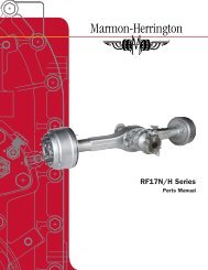
workshop manual rear axles rf17n/h r17n/h - Marmon-Herrington
workshop manual rear axles rf17n/h r17n/h - Marmon-Herrington
workshop manual rear axles rf17n/h r17n/h - Marmon-Herrington

You also want an ePaper? Increase the reach of your titles
YUMPU automatically turns print PDFs into web optimized ePapers that Google loves.
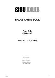
WORKSHOP MANUAL<br />
REAR AXLES<br />
RF17N/H R17N/H<br />
MARMON-HERRINGTON ALL WHEEL DRIVE<br />
13001 Magisterial Drive • Louisville, KY 40223<br />
(502) 253-0277 • (800) 227-0727 • Fax (502) 253-0317<br />
E-mail: info@marmon-herrington.com<br />
1
SECTION 202.<br />
CONTENTS<br />
PREFACE 7<br />
GENERAL WORKING DIRECTIONS 8<br />
FOREWORD 9 203<br />
DRAWINGS OF THE AXEL 11 204<br />
TECHNICAL DATA 12 205<br />
Types 12<br />
Wheel Brake 14<br />
Rolling Bearings 15<br />
Seals 17<br />
TORQUE RATINGS 18 206<br />
Wheel Hub 18<br />
Wheel Brake 18<br />
Main Differential 20 207<br />
Differential Carrier Head 21<br />
ADJUSTMENT DATA 22 207<br />
Wheel Drive and Wheel Hub 22<br />
Wheel Brake 22<br />
Differential Carrier Head 22<br />
PULLER AND PILOT BOLTS 24 208<br />
GENERAL SERVICE INSTRUCTIONS 25 209<br />
Wheel Drive and Wheel Hub 25<br />
Wheel Brake 25<br />
Differential Carrier Head 25<br />
General Instructions 25<br />
Application of “LOCLITE” Bolt Securing System 25<br />
WHEEL DRIVE, WHEEL HUB 26<br />
Sectional View of the Wheel Hub 26 210<br />
Parts of the Wheel Drive and Wheel Hub 27 211<br />
3
4<br />
Removing and Reinstalling the Wheel Disk 28 212<br />
Removing and Reinstalling the Brake Drum 28 213<br />
Removing and Reinstalling the End-Cover 28 214<br />
Removing and Reinstalling the Axle Shaft<br />
and the Sun Gear, Adjusting the Axle Shaft Clearance 28 219<br />
Removing and Reinstalling the Planet Carrier<br />
Adjusting the Axle Shaft Clearance 29 220<br />
Disassembling and Reassembling<br />
the Planetary Gear 29 221<br />
Removing and Reinstalling the Wheel Hub 30 223<br />
Disassembling and Reassembling<br />
the Wheel Hub 31 224<br />
Disassembling and Reassembling<br />
the Rim Hub 33 225<br />
Removing and Reinstalling the Spindle 34 226<br />
Installation Instructions for Parts of<br />
Antiblocking System 34 229<br />
WHEEL BRAKE 35<br />
Drawing of the Wheel Brake 36 260<br />
Parts of the Wheel Brake 37 261<br />
Removing and Reinstalling the Brake Shoes 38 262<br />
Repairing the Brake Shoes and<br />
the Brake Drum 39 263<br />
Removing and Reinstalling the Brake Support<br />
and the Diaphragm Holder, Assembling<br />
the Supporting Pins 40 264<br />
Removing and Reinstalling the Brake Lever<br />
and the Brake Spanner 41 265<br />
Repairing the Brake Spanner Bearing Support 42 266<br />
Automatic Slack Adjuster 44 268<br />
MAIN DIFFERENTIAL 45<br />
Main Differential Sectional View 46 280
Parts of Main Differential 47 281<br />
Removing and Reinstalling the Main Differential 49 282<br />
Removing and Reinstalling the Companion<br />
Flanges and the Cover, Replacing the Oil<br />
Seals in the Cover 49 283<br />
Removing and Reinstalling the Thru-Drive Shaft 52 284<br />
Removing the Input Shaft and Differential Carrier III. 53 285<br />
Removing and Reinstalling the Cross Differential,<br />
Adjusting the Backlash and the Contact Pattern 54 287<br />
Disassembling and Reassembling the Differential 57 288<br />
Removing and Reinstalling the Differential<br />
Carrier II. Adjusting the Axis Distance 59 289<br />
Disassembling and Reassembling the Carrier II. 60 290<br />
Reinstalling the Input Shaft and the<br />
Differential Carrier III. 65 292<br />
Adjusting and Checking the Axial Play<br />
of the Input Shaft 69 293<br />
Repairing, Reinstalling and Adjusting the<br />
Inter-Axle Differential Lock 70 294<br />
Disassembling and Reassembling the Oil Pump 71 295<br />
DIFFERENTIAL CARRIER ASSEMBLY 72<br />
Differential Carrier Assembly Sectional View 72 310<br />
Parts of the Differential Carrier Assembly 73 311<br />
Removing and Reinstalling the Differential Carrier Assembly 74 312<br />
Removing and Reinstalling the Companion Flange<br />
and the Cover, Replacing the Oil Seal 74 313<br />
Removing and Reinstalling the Differential,<br />
Adjusting the Backlash and the Contact Pattern 77 314<br />
Disassembling and Reassembling the Differential 81 315<br />
Removing and Reinstalling the Bearing Cage 82 316<br />
Disassembling and Reassembling the Bearing Cage 84 317<br />
Repairing, Reinstalling, Adjusting the Differential Lock 88 395<br />
Oil Fill-Up, Run, Check 90 395<br />
5
PREFACE<br />
The present document gives directions to the trained personnel to repair the<br />
RF17/R17 Rear Axles<br />
Customary tools and devices, which are <strong>workshop</strong> standard, are assumed to be available.<br />
Dissasembly and assembly of one version only is explained in this document. Differing working sequences<br />
of other possible versions can be recognized by the skilled professional. For such jobs see<br />
enclosed sectional and perspective views.<br />
Damages caused by improperly or unprofessionally executed repair work throu untrained personnel<br />
and the resulting consequences are excluded from any contractual liability.<br />
Use only <strong>Marmon</strong>-<strong>Herrington</strong> parts. Seal and bearings are proprietary throughout.<br />
7
8<br />
GENERAL WORKING DIRECTIONS<br />
Individuals repairing <strong>Marmon</strong>-<strong>Herrington</strong> equipment are responsible for all aspects of safety.<br />
All safety regulations must be observed to avoid personal injury or property damage.<br />
Proper mechanical training is required, and is the responsibility of the repair person or facility. <strong>Marmon</strong>-Hearington<br />
shall not be liable for personal injury or property damage resultant of inadequately<br />
trained personnel.<br />
Always ensure a clean working environment. Parts and components must always be cleaned before<br />
assembly.<br />
Always ensure that proper tools and equipment are available. Common hand and air tools are reffered<br />
to throughout this <strong>manual</strong>. Most special tools can be fabricated in the shop environment.<br />
The condition of all parts must be checked prior to final assembly. This includes wear items such as<br />
seals, bearings, o-rings, etc.<br />
Observe all adjustment tolerances and torque requirements. Ensure that proper lubes and capacities<br />
are checked before operation.<br />
Use original <strong>Marmon</strong>-Hearington parts only.
This <strong>manual</strong> has been prepared for owners and operators<br />
of vehicles equipped with <strong>Marmon</strong>-<strong>Herrington</strong><br />
All-Wheel-Drive systems and components. For additional<br />
technical assistance, contact <strong>Marmon</strong>-<strong>Herrington</strong><br />
Customer Service.<br />
Please observe and follow all procedural and maintenance<br />
guidelines to ensure reliable operation and<br />
optimum service life. The <strong>Marmon</strong>-<strong>Herrington</strong> basic<br />
service schedule will integrate seamlessly with most<br />
preventative maintenance programs.<br />
<strong>Marmon</strong>-<strong>Herrington</strong> shall not be liable for component<br />
failures or damages caused by operational abuse or<br />
neglect. Please review the Warranty Statement for a<br />
detailed explanation of coverage and claim reporting<br />
procedures.<br />
We thank you for your investment in <strong>Marmon</strong>-<strong>Herrington</strong><br />
equipment, and look forward to serving your<br />
needs in the tradition of engineering excellence.<br />
GENERAL OPERATION STATEMENT<br />
As close as engineers try to match gear ratios and<br />
tires for a given application, the reality is that there will<br />
always be some degree of ratio mis-match between<br />
front and <strong>rear</strong> <strong>axles</strong>. When a vehicle is operated on a<br />
hard, dry surface with the front axle engaged (AWD,<br />
4X4, 6X6 modes), the tires are not able to slip and<br />
relieve the torsional forces being generated.<br />
As such, <strong>Marmon</strong>-<strong>Herrington</strong> equipped vehicles are<br />
designed for “as needed” AWD operation only, in<br />
“off-raod” or poor traction conditions. They are not<br />
intended to be driven in AWD mode on hard, dry surfaces.<br />
Note: Seek expert advice when considering tire size<br />
or gear ratios changes.<br />
SHIFTING OF AXLE OR TRANSFER CASE<br />
<strong>Marmon</strong>-<strong>Herrington</strong> Axles and Transfer Cases use<br />
no clutching or synchronization devices, and there-<br />
SECTION 203.<br />
FOREWORD<br />
fore should only be shifted when the vehicle is at a<br />
complete stop. This applies to front axle engagement,<br />
high and low ranges, and locking differentials.<br />
The only exceptions are those vehicles equipped with<br />
<strong>Marmon</strong>-<strong>Herrington</strong>’s Safety-Shift system, which are<br />
calibrated to shift up to 5 mph.<br />
“Shifting on the fly” generally results in two types of<br />
damage. The first is degradation of the engagement<br />
teeth due to relative rotation of the drive gears and<br />
shift collars. This type of damage can prevent the<br />
case from shifting normally, as the teeth become<br />
burred and cannot mesh.<br />
The second condition occurs when a shift is actually<br />
completed at excessive speed. This results in extreme<br />
torque loading that is transmitted through the<br />
transfer case, drive shafts, and <strong>axles</strong>. The extent of<br />
possible damage increases proportionately with the<br />
vehicle speed.<br />
SUMMARY<br />
Before retreating from the subject of shifting, it must<br />
be reemphasized that no transfer case, PTO, axle<br />
differential, or power divider should ever be shifted<br />
while the vehicle is in motion. The engagement<br />
of these components is intended for off-road only,<br />
in poor traction conditions.<br />
TORQUE<br />
“Torque Shock” or “Torque Loading” is a damaging<br />
mode of failure that is easily avoidable. It generally<br />
occurs in situations wherein a vehicle is operating in<br />
an area of low traction at high RPM with the wheels<br />
spinning. When the tires make abrupt contact with a<br />
tractable surface, a violent shock-load is transmitted<br />
through the drive train. This can result in damages<br />
to <strong>axles</strong>, drive shafts, transfer cases and transmissions.<br />
Simply engaging the front axle and operating in low<br />
range at lower speeds will allow the vehicle to proceed<br />
without imparting undue stress to the drive train.<br />
9
204 FEJEZET SECTION 204<br />
A FUTÓM�VEK ÁBRÁJA<br />
DRAWING OF THE AXLES<br />
A Tandem futóm�vek<br />
Típus<br />
Összáttétel A hajtókúpkerék foghajlás<br />
rajzszáma<br />
Zeichnungs-Nr. Drawing number der tandem Achsen<br />
Drawing number <strong>axles</strong> of tandem<br />
Typ<br />
Type<br />
Gesamtübersetzung<br />
Total ratio iránya<br />
Spiralrichtung Drive pinion hand des<br />
Antriebskegelrades<br />
of spiral<br />
<strong>axles</strong><br />
Drive pinion hand of spiral<br />
739.43-3300-000 RF17<br />
Tandem RF17 I. 5,283 jobb / rechts / right<br />
739.93-3300-000 R17<br />
Tandem R17 II 5,283 bal / links / left<br />
10<br />
Menetirány<br />
Forward direction<br />
MOM 2393-<br />
SECTION 204.<br />
DRAWING OF THE AXLE<br />
739.43 RF17/R17 / 93<br />
11
205. FEJEZET SECTION 205.<br />
SECTION 205.<br />
M�SZAKI ADATOK<br />
TECHNICAL DATA<br />
TECHNICAL DATA<br />
MEGNEVEZÉS<br />
BENENNUNG<br />
DESIGNATION<br />
A FUTÓM�VEK RENDSZERE :<br />
12<br />
MÉRTÉK-<br />
EGYSÉG<br />
MASSEIN- UNITS<br />
HEIT<br />
UNITS<br />
TÍPUS TYPE TYP TYPE<br />
739.43 RF17 739.93 R17<br />
A SYSTEM futóm� áttételezése OF AXLE: kétfokozatú. A hajtóm�ben ívelt fogazatú tányér- és kúpkerékpár, a<br />
kerékagyban homlokkerekes bolygóm� adja az áttételt.<br />
The reduction of the axle is of a two-stage design. The reduction is accomplished<br />
SYSTEM by a pinion OF and THE drive AXLE: gear in the carrier and by spur planetary gearing in the wheel hub.<br />
The reduction of the axle is of two-stage design. The reduction is accomplyshed by a pinion and<br />
drive gear in the carrier and by spur planetary gearing in the wheel hub.<br />
MÉRETEK<br />
DIMENSIONS<br />
Nyomtáv<br />
Wheel track<br />
Legnagyobb szélesség<br />
Overall width<br />
ÁTTÉTELEK<br />
RATIOS<br />
Tányér- / meghajtó-kúpkerék fogszám<br />
Drive gear- / drive / drive pinion pinion tooth tooth<br />
number<br />
Hajtó-/hajtott fogaskerék fogszáma<br />
Spur gear/Driven gear<br />
Bolygóm�<br />
Planetary gear gear<br />
Összáttétel<br />
Total ratio<br />
mm 2059<br />
mm<br />
2059<br />
mm 2492<br />
mm<br />
2492<br />
mm inches<br />
29 / 19<br />
29/19<br />
23 23/23 / 23<br />
64<br />
64<br />
/ 26<br />
/ 26<br />
+<br />
+1<br />
1<br />
= 3,461<br />
3,461<br />
5,283<br />
5.283<br />
81.06<br />
98.11<br />
11
M�SZAKI ADATOK<br />
TECHNICAL DATA<br />
MEGNEVEZÉS<br />
BENENNUNG<br />
DESIGNATION<br />
ÁLTALÁNOS ADATOK<br />
GENERAL DATA<br />
Névleges tengelyterhelés<br />
Nominal axel axle load load<br />
Max. járm�súly<br />
Max Max. G.V.W.<br />
Megengedett összgördül� tömeg<br />
Permitted total rolling masse masse<br />
Országuton<br />
On highway operation<br />
On highway operation<br />
Megengedett behajtó nyomaték<br />
Permitted input torque<br />
Max. kihajtó nyomaték<br />
Max. output torque<br />
Max. kihajtó fordulatszám<br />
Max. output speed revolution<br />
Max. motorteljesítmény<br />
Max. engine performance<br />
A futóm� tömege olajfeltöltés nélkül<br />
Axle mass without oil oil fill fill<br />
Kiegyenlít�m�zár<br />
Differential lock lock<br />
Futóm�vek közötti kiegyenlít�m�zár<br />
Inter axle differential lock lock<br />
ABS szerkezeti elemek<br />
Parts of of the ABS<br />
Gerjeszt�gy�r�<br />
Impulse generating ring ring<br />
12<br />
MÉRTÉK-<br />
EGYSÉG<br />
MASSEIN- UNITS<br />
HEIT<br />
UNITS<br />
205<br />
TÍPUS TYPE TYP TYPE<br />
739.43 RF17 739.93 R17<br />
Nm SAE<br />
kg 7700<br />
kg<br />
7700 7700<br />
kg 22600<br />
kg<br />
22600 22600<br />
kg<br />
46000 46000<br />
Nm 15320<br />
Nm<br />
15320 15320<br />
Nm 30000<br />
Nm<br />
30000 30000<br />
1/min 500<br />
1/min<br />
500 500<br />
kW 280<br />
kW<br />
280 280<br />
kg 702 628<br />
kg<br />
720<br />
628 1587/1385<br />
van<br />
Yes is<br />
van<br />
Yes is<br />
Beépíthet�<br />
Can be installed<br />
Beépített<br />
Can Installed be installed<br />
16,975<br />
49,824<br />
101,412<br />
11,300<br />
22,126<br />
500<br />
375<br />
205<br />
13
M�SZAKI ADATOK<br />
TECHNICAL DATA<br />
MEGNEVEZÉS<br />
BENENNUNG<br />
DESIGNATION<br />
A KERÉKAGY KIVITELE<br />
WHEEL HUB EXECUTION<br />
EXECUTION<br />
Keréktárcsa felszerelésére alkalmas.<br />
For installing wheel disk<br />
Nominal axel load<br />
A KERÉKFÉK<br />
WHEEL BRAKE<br />
14<br />
MÉRTÉK-<br />
EGYSÉG<br />
MASSEIN- UNITS<br />
HEIT<br />
UNITS<br />
mm<br />
kg<br />
Rendszere : A kerékfék szimplex rendszer� bels�pofás dobfék.<br />
System System: : The wheel brake brake is of is simplex of simplex system system internally internally acting acting drum brake. drum brake.<br />
Fékdobátmér�<br />
Brake drum diameter<br />
Max. felszabályozott fékdobátmér�<br />
Max. trued-up brake drum drum diameter<br />
Fékbetét szélesség<br />
Brake lining width<br />
Hézag a fékbetét és fékdob között (beállításkor)<br />
Brake shoe shoe clearance (at adjustment)<br />
A fékkulcs max. radiális játéka<br />
(fékkulcspersely kopás)<br />
Max. radial Spiel play of des the Bremsnockenwelle<br />
camshaft<br />
(Bremsnocken-Buchse Verschleiss)<br />
(camshaft bushing wearing)<br />
Max. radial play of the camshaft<br />
(camshaft bushing wearing)<br />
Min. fékbetét vastagság a fékpofa közepén<br />
mérve Min. (a brake fékbetét lining oldalán thickness a beszúrás measured fels� éle at<br />
jelzi) brake shoe center<br />
Min. brake lining thickness measured at brake<br />
shoe (marked center by (marked upper edge by upper of recess edge of onrecess<br />
on<br />
side of brake lining)<br />
Max fékkulcsnyomaték/fékdobnyomaték<br />
Max.camshaft torque/brake drum torque<br />
µ=0,35 Max. camshaft torque/brake drum torque<br />
mm<br />
mm mm<br />
mm<br />
205<br />
TÍPUS TYPE TYP TYPE<br />
739.43 RF17/R17 / 93<br />
205<br />
Perem átmér� :<br />
Flange diameter 219,8<br />
Flange diameter<br />
distance: Kerékanya laptáv :<br />
219.8 8.65hhex.<br />
Wheel nut hex. distance:<br />
420<br />
424 424<br />
180<br />
mm<br />
0,3 0.3 - 0.6 0,6<br />
mm<br />
mm<br />
0,4<br />
0.4<br />
mm 7<br />
mm<br />
7<br />
Nm<br />
Nm<br />
mm in<br />
Metric SAE<br />
Nm lbs<br />
1760/17072<br />
1760/17072<br />
16.535<br />
16.693<br />
7.09<br />
0.011-0.24<br />
0.015<br />
0.27<br />
1298/12591<br />
13
M�SZAKI ADATOK<br />
TECHNICAL DATA<br />
MEGNEVEZÉS<br />
BENENNUNG<br />
DESIGNATION<br />
14<br />
MÉRTÉK-<br />
EGYSÉG<br />
MASSEIN- UNITS<br />
HEIT<br />
UNITS<br />
205<br />
TÍPUS TYPE TYP TYPE<br />
RF17/R17 739.43 / 93<br />
FÉKKAR Rendszere : MOM automatikus utánállítású<br />
SLACK ADJUSTER System: MOM automatic System slack : adjuster MOM automatic slack adjuster<br />
mm in<br />
A fékkar beépítési sugara<br />
Slack adjuster installation radius “C” "C"<br />
A fékkarpersely furatközepe és a<br />
membrántartó felfekv� síkja közötti<br />
Distance of slack adjuster bushing bore<br />
távolság "A"<br />
center from seating plane of the<br />
Distance of slack adjuster bushing bore center<br />
chamber bracket “A”<br />
from seating plane of the chamber bracket<br />
GÖRDÜL�CSAPÁGYAK<br />
ANTIFRICTION BEARINGS<br />
ANTIFRICTION BEARINGS<br />
Kerékagyban<br />
In In Wheel Hub<br />
Küls� : kúpgörg�s csapágy<br />
Outer : taper roller bearing<br />
Outer Brake drum : taper diameter roller bearing<br />
Bels� : kúpgörg�s csapágy<br />
Inner : : taper roller bearing bearing<br />
Kerékagy bolygóm�ben<br />
In In wheel Wheel hub Hub planetary gear gear<br />
mm<br />
175<br />
mm<br />
mm<br />
83<br />
83<br />
30218 A MGM<br />
32218 A MGM<br />
32218 A MGM<br />
Hengergörg�s csapágy<br />
Cylindric roller bearing<br />
Cylindric roller bearing<br />
K 30x42x30 0.3 MGM - MGM 0.6<br />
Meghajtó kúpkeréken<br />
On On drive pinion<br />
Küls� : kúpgörg�s csapágy<br />
Outer : taper roller bearing<br />
Outer : taper roller bearing<br />
Bels� : kúpgörg�s csapágy<br />
Inner : taper roller bearing<br />
Inner : taper roller bearing<br />
32312 B J2Q LC7<br />
32312 B J2Q LC7<br />
32312 CJR KOYO<br />
32312 CJR KOYO<br />
32314 B J2Q LC7<br />
32314 CJR KOYO<br />
32314 B J2Q LC7<br />
32314 CJR KOYO<br />
6.88<br />
205<br />
15
M�SZAKI ADATOK<br />
TECHNICAL DATA<br />
MEGNEVEZÉS<br />
BENENNUNG<br />
DESIGNATION<br />
GÖRDÜL�CSAPÁGYAK<br />
ANTIFRICTION<br />
ANTIFRICTION<br />
BEARINGS<br />
BEARINGS<br />
Kiegyenlít�m�vön<br />
On On differential<br />
Peremes házfélen : kúpgörg�s<br />
On flanged case half :<br />
csapágy taper roller bearing<br />
On flanged case half : taper roller<br />
bearing<br />
Házfélen : kúpgörg�s csapágy<br />
On half case : taper : taper roller roller bearing bearing<br />
Behajtó tengelyen<br />
On input shaft<br />
MÉRTÉK-<br />
EGYSÉG<br />
MASSEIN- UNITS<br />
HEIT<br />
UNITS<br />
Küls�: Kúpgörg�s csapágy<br />
Outer: Outer : Taper Taper roller roller bearing bearing<br />
32212 SKF<br />
32212 CR KOYO<br />
32212 CR KOYO<br />
Bels�: Kúpgörg�s csapágy<br />
Inner: Inner : Taper Taper roller roller bearing bearing<br />
30214 X SKF<br />
32012 JR KOYO<br />
32014 JR KOYO<br />
Áthajtó tengelyen<br />
On thru-drive thu-drive shaft<br />
Mélyhornyú golyós csapágy<br />
Deep-groove ball ball bearing 6210 RC3 KOYO<br />
6210 RC3 KOYO<br />
16 15<br />
205<br />
TÍPUS TYPE TYP TYPE<br />
739.43 RF17 739.93 R17<br />
32215 SKF;<br />
32215 JR KOYO<br />
32215 SKF;<br />
32215 JR KOYO<br />
30215 SKF;<br />
30215 30215 JR KOYO<br />
205
M�SZAKI ADATOK<br />
TECHNICAL DATA<br />
MEGNEVEZÉS<br />
MÉRTÉK<br />
-EGYSÉG<br />
BENENNUNG<br />
TÍPUS TYP TYPE<br />
MASSEIN<br />
DESIGNATION UNITS TYPE<br />
TÖMÍT�GY�R�K<br />
SEALS<br />
SEALS<br />
In Kerékagyban<br />
the wheel hub<br />
In wheel hub<br />
16<br />
HEIT<br />
UNITS<br />
205<br />
739.43 RF17 739.93 R17<br />
1HH1 145x175x17.54-NB<br />
1HH1 STEFA 145x175x17.54-NB<br />
DENSO<br />
STEFA DENSO<br />
A fékkulcs csapágyházban<br />
In camshaft chamsaft bushing bracket bracket<br />
42x55x8 42x55x8 NB NB SEMPERFORM<br />
Hajtóm�ben<br />
In differential<br />
In differential<br />
F�hajtóm�ben<br />
In In main main differential differential<br />
Behajtótengelyen<br />
Input shaft<br />
Input shaft<br />
Áthajtó tengelyen<br />
Through shaft<br />
Through shaft<br />
---<br />
A 75x95x10 NB<br />
SIMMERWERKE;<br />
A 75x95x10 NB<br />
SIMMERWERKE;<br />
AS AS 75x95x10 75x95x10 NB NB<br />
SIMMERWERKE<br />
SIMMERWERKE<br />
SIMMERWERKE<br />
ASL ASL 65x90x10/12 NB; NB;<br />
SIMMERWERKE<br />
A 65x90x10 NB<br />
A 65x90x10 NB<br />
AS 75x95x10 NB NB<br />
SIMMERWERKE;<br />
A 75x95x10 NB<br />
SIMMERWERKE<br />
---<br />
---<br />
205<br />
17
206. FEJEZET SECTION 206.<br />
MEGHÚZÁSI NYOMATÉKOK<br />
SECTION 206.<br />
TORQUE RATINGS<br />
TORQUE RATINGS<br />
A sorszámok The serial a "JAVÍTÁSI numbers UTASÍTÁS are the item numbers " ábráinak of the tételszámai. figures in the “REPAIR INSTRUCTION”.<br />
The serial numbers are the item numbers of the figures in the " REPAIR INSTRUCTION ".<br />
MEGNEVEZÉS<br />
BENENNUNG<br />
DESIGNATION<br />
DESIGNATION<br />
FEJEZET /<br />
ÁBRASSZÁM<br />
SECTION/<br />
FIG. SECTION ITEM No. /<br />
FIG. ITEM No<br />
TÍPUS TYP TYPE<br />
TYPE<br />
739.43 RF17/R17 / 93<br />
KERÉKAGY<br />
WHEEL HUB<br />
WHEEL HUB 210 210/1 / 1 Nm Nm mm<br />
in<br />
Kerékanyák<br />
A megerendel� el�írásai szerint.<br />
Wheel nuts<br />
As specified As specified by the orderer by the orderer 20 - 25<br />
A kerékagy fedelet feler�sít� csavarok<br />
Wheel hub cover bolts bolts<br />
6<br />
20 - 25 20 - 25<br />
Fékdobot feler�sít� csavarok<br />
Brake drum mounting bolts bolts<br />
24 39 - 49<br />
24 39 - 49<br />
Bolygótartót feler�sít� csavarok<br />
Planetary carrier mounting bolts bolts 26 39 - 49<br />
26 39 - 49<br />
Tengelyvéganya (bels�) 223. fejezet<br />
szerint<br />
36 196<br />
Spindle nut (inner) Per section 223 36 196<br />
Spindle nut (inner) Per section 223<br />
Tengelyvéganya (küls�)<br />
Spindle nut nut (outer) 34 34 450 - 490 588 - 637<br />
Tengelycsonkot a hidházhoz rögzít�<br />
csavarok<br />
Spindle to axle housing mounting bolts<br />
Spindle to axle housing mounting<br />
bolts<br />
Olajbetölt� és olajszintellen�rz�<br />
41<br />
41<br />
360 - 380<br />
Menetrögzít� 360 - 380 anyaggal szerelve<br />
265 - 280<br />
Mounted Mounted with thread with locker thread locker<br />
csavarok<br />
Oil filling and level plugs<br />
Oil filling and level plugs<br />
55 - 85<br />
55 - 85<br />
40 - 60<br />
KERÉKFÉK<br />
WHEEL HUB BRAKE<br />
18<br />
260 210/1 / 1 Nm Nm mm<br />
Membrántartót rögzít� hatlapfej�<br />
130 - 140<br />
csavarok<br />
Chamber bracket mounting hex. bolts<br />
Chamber bracket mounting hex. bolts<br />
Féktakarólemezt feler�sít� csavarok<br />
16<br />
16<br />
Menetrögzít� 130 - 140 anyaggal szerelve<br />
95 - 103<br />
Mounted Mounted with thread with locker thread locker<br />
Dust shield mounting bolts bolts<br />
21 10 - 12 10 - 12<br />
7 - 8.5<br />
Fékkar ütköz�t rögzít� csavarok<br />
Hex. bolts mounting stop stop of the of the<br />
automatic slacker slack adjuster<br />
29 20 - 25<br />
29 20 - 25<br />
15 - 18<br />
28 - 36<br />
28 - 36<br />
145<br />
330 - 360<br />
lbs<br />
15 - 18<br />
17
MEGHÚZÁSI NYOMATÉKOK<br />
TORQUE RATINGS<br />
MEGNEVEZÉS<br />
BENENNUNG<br />
DESIGNATION<br />
18<br />
FEJEZET /<br />
ÁBRASSZÁM<br />
ABSCHN. /<br />
BILD<br />
SECTION/<br />
LFD. Nr<br />
SECTION /<br />
FIG. ITEM No.<br />
F�HAJTÓM�<br />
310/1<br />
WHEEL HUB 310/1 Nm<br />
MAIN DIFFERENTIAL CARRIER HEAD<br />
Hajtóm�házat a hídházhoz rögzít� csavarok<br />
Differential Differential carrier housing to axle to axle causing causing<br />
mounting bolts bolts<br />
44<br />
44<br />
206<br />
TÍPUS TYPE TYP TYPE<br />
739.43 RF17<br />
Nm<br />
88 - 98<br />
88 - 98<br />
Menetrögzít�vel szerelve 65 - 72<br />
Mount with<br />
Mount<br />
thread<br />
with<br />
locker<br />
thread locker<br />
Kapcsolóagyakat rögzít� peremes koronás anyák<br />
Flanged castle nuts nuts of of companion campanion flanges flanges<br />
1 850 - 1050850<br />
- 1050<br />
Hajtott fogaskereket a meghajtó kúpkerékhez<br />
rögzít� koronás anya<br />
Drive gear to drive pinion castle nut<br />
Drive gear to drive pinion castle nut<br />
52<br />
52<br />
850 - 1050850<br />
- 1050<br />
Fedelet rögzít� csavarok<br />
Cover mounting bolts 6 59 - 78<br />
59 - 78<br />
Hajtóm�ház II...III-at egymással összefogó<br />
csavarok<br />
Differential carrier housing II…III clamp bolts<br />
Differential carrier housing II...III clamp bolts<br />
Hajtóm�ház I...II-t egymással összefogó<br />
14<br />
88.3 - 98 88,3 - 98<br />
Menetrögzít�vel szerelve 65 - 72<br />
Mount with thread locker<br />
Mount with thread locker<br />
csavarok<br />
Differential carrier housing II…III clamp bolts<br />
Differential carrier housing I...II clamp bolts<br />
52<br />
52<br />
160 - 180<br />
160 - 180<br />
118 - 130<br />
Fogazott tárcsát felfogó anya<br />
Toothed disk lock nut<br />
57<br />
Toothed disc lock nut 57<br />
Olajszivattyú fedelet I. rögzít� csavar<br />
Oil pump cover I. I. mounting bolt bolt<br />
54 13<br />
Hosszirányú kiegyenlít�m�ház-feleket összefogó<br />
csavarok<br />
Clamp bolt of intermediate differential<br />
Clamp bolts of intermediate differential case<br />
halves case halves<br />
Áthajtótengely csapágyhüvelyét rögzít� csavarok<br />
Thru-drive shaft bearing cage castle nut<br />
Thru-drive shaft bearing cage castle nut<br />
FIG. ITEM No.<br />
93<br />
93<br />
109<br />
93<br />
37<br />
37 Lemezzel biztosítva<br />
Secured Securited with threadwith<br />
thread<br />
13<br />
lbs<br />
625 - 775<br />
625 - 775<br />
43 - 57<br />
27<br />
9.5<br />
25 - 30<br />
Menetrögzít�vel 25 - 30 szerelve 18 - 22<br />
Mount with Mount thread with locker thread locker<br />
39 - 496<br />
39 - 49<br />
Menetrögzít�vel szerelve 28 - 36<br />
Mount with<br />
Mount<br />
thread<br />
with<br />
locker<br />
thread locker<br />
206<br />
19
MEGHÚZÁSI NYOMATÉKOK<br />
TORQUE RATINGS<br />
MEGNEVEZÉS<br />
DESIGNATION<br />
F�HAJTÓM�<br />
MAIN DIFFERENTIAL CARRIER<br />
MAIN DIFFERENTIAL CARRIER<br />
HEAD<br />
20<br />
Fejezet/Ábraszám<br />
SECTION/<br />
LFD. No.<br />
FIG. ITEM No.<br />
Section / Fig.<br />
ITEM No.<br />
310/1<br />
310/1 Nm<br />
Olajszivattyút rögzít� csavarok<br />
Oil pump mounting bolts 66 58.8 - 78.6<br />
Behajtó tengely fedelet rögzít� csavar<br />
Input Input shaft cover mounting bolts bearing<br />
cage cage<br />
Az orros biztosítólemezeket feler�sít�<br />
csavarok<br />
Adjuster lock plate mounting bolts<br />
Adjuster lock plate mounting bolts<br />
22<br />
22 15 - 20<br />
Kiegyenlít�m�ház feleket összefogó<br />
csavarok<br />
Differential case halves clamp bolts<br />
Differential case halves clamp bolts<br />
25<br />
25 49 - 59<br />
Tányérkereket rögzít� csavarok<br />
Drive Driven pinion mounting bolts 39 120 - 135<br />
KIEGYENLÍTÓM�ZÁR<br />
DIFFERENTIAL LOCK<br />
330/1<br />
DIFFERENTIAL LOCK 310/1 Nm<br />
A m�ködtet� légkamrát rögzít� anya<br />
Actuating Actuating air chamber lock lock nut nut<br />
16 29 - 39<br />
Légkamra bilincsek anyái<br />
---<br />
Air chamber half nuts --- 2.5<br />
6<br />
6<br />
58.8 - 78.6<br />
TÍPUS TYPE TYPE<br />
739.43 RF17<br />
Nm<br />
58,8- 78,6<br />
58,8- 78,6<br />
15 - 20<br />
49 - 59<br />
120 - 135<br />
Nm<br />
29 - 39<br />
2,5<br />
lbs<br />
43 - 57<br />
43 - 57<br />
11 - 15<br />
36 - 43<br />
88 - 99<br />
lbs<br />
21 - 28<br />
2<br />
206<br />
206<br />
19
MEGHÚZÁSI NYOMATÉKOK<br />
TORQUE RATINGS<br />
MEGNEVEZÉS<br />
DESIGNATION<br />
20<br />
Fejezet/Ábraszám<br />
SECTION/<br />
LFD. No.<br />
FIG. ITEM No.<br />
Section / Fig.<br />
ITEM No.<br />
TÍPUS TYPE TYPE<br />
739.93 R17<br />
HAJTÓM�<br />
310/1<br />
Nm<br />
DIFFERENTIAL CARRIER HEAD<br />
DIFFERENTIAL CARRIER HEAD 310/1 Nm<br />
Nm<br />
Hajtóm�házat a hídházhoz rögzít� csavarok<br />
Differential carrier housing to to axle axle housing housing<br />
mounting<br />
mounting<br />
bolts<br />
bolts<br />
Meghajtó kúpkerék koronás anyája<br />
Drive pinion castle nut nut<br />
--- -<br />
88 - 98<br />
Menetrögzít� 88 - 98 anyaggal szerelve<br />
65 - 72<br />
Mount with Mounted thread with locker thread locker<br />
1<br />
650 - 700<br />
650 - 700<br />
Hajtóm�ház fedelet rögzít� csavarok<br />
Differential carrier cover mounting bolts bolts<br />
6 20 - 30<br />
20 - 30<br />
Csapágyhüvelyt rögzít� csavarok<br />
Bearing cage mounting bolts<br />
Bearing cage mounting bolts<br />
14<br />
14<br />
88 - 98<br />
Menetrögzít� 88 - 98 anyaggal szerelve<br />
15 - 22<br />
Mount with Mounted thread with locker thread locker<br />
Az orros biztosítólemezeket rögzít� csavarok<br />
Adjuster lock lock plate plate mounting bolts bolts<br />
22<br />
22 15 - 20<br />
15 - 20<br />
Kiegyenlít�m�ház feleket összefogó csavarok<br />
Differential case case halves halves clamp clamp bolts bolts<br />
25<br />
25 49 - 59 49 - 59<br />
120 - 135<br />
Tányérkereket feler�sít� csavarok<br />
39<br />
Ring gear gear mounting bolt bolt<br />
39 120 - 135<br />
A m�ködtet� légkamrát felfogó csavarok<br />
Bolts mounting the the actuating air air chamber chamber lock lock -<br />
--- 29 - 39<br />
Kiegyenlít�m�zár m�ködtet� légkamrát<br />
összefogó Nuts of clamps bilincsek for diff. rögzít� lock anyái actuating air chamber<br />
Nuts of clamps for diff. lock actuating air chamber<br />
-<br />
--- 2.5<br />
29 - 39<br />
2,5<br />
lbs<br />
480 - 512<br />
65 - 72<br />
11 - 15<br />
36 - 43<br />
88 - 99<br />
21 - 28<br />
2<br />
206<br />
21
207. FEJEZET SECTION 207.<br />
BEÁLLÍTÁSI ADATOK<br />
ADJUSTMENT DATA<br />
SECTION 207.<br />
ADJUSTMENT DATA<br />
MEGNEVEZÉS<br />
BENENNUNG<br />
DESIGNATION UNITS<br />
DESIGNATION<br />
KERÉKAGY<br />
WHEEL HUB<br />
WHEEL HUB<br />
Kerékagy-csapágyak tengelyirányú játéka :<br />
(beállítása állítólemezekkel)<br />
Axial play of the wheel hub bearings :<br />
Axial play of wheel hub bearings :<br />
(adjusted by the spindle nuts)<br />
(adjustment by shims)<br />
KERÉKFÉK<br />
WHEEL BRAKE<br />
WHEEL BRAKE<br />
MÉRTÉK-<br />
EGYSÉG<br />
MASSEIN-<br />
HEIT<br />
UNITS<br />
Hézag a fékbetét és a fékdob között<br />
(beállításkor)<br />
Shoe clearance (during adjustment)<br />
Shoe clearance (during adjustment)<br />
mm<br />
mm 0.3 - 0.6<br />
TÍPUS TYPE TYP TYPE<br />
739.43 RF17 739.93 R17<br />
mm 0.01 - 0.04 0,01 - 0,04 0.0004 - 0.0016<br />
0,3 - 0,6<br />
A fékkulcs tengelyirányú játéka<br />
Axial play of of camshaft mm 0.1 - 0.5 0,1 - 0,5<br />
HAJTÓM�VEK<br />
DIFFERENTIAL CARRIER HEADS<br />
Foghézag a meghajtó kúpkerék és a<br />
tányérkerék Drive pinion között to drive gear backlash<br />
GLEASON-fogazat GLEASON-toothing (ground) (köszörült)<br />
Drive pinion to drive gear backlash<br />
GLEASON-toothing (ground)<br />
A meghajtó kúpkerék legördülési<br />
nyomatéka a csapágyak el�feszítése<br />
után Drive (tömít�gy�r� pinion rolling torque, nincs after felszerelve,<br />
beállítása pre-loading távtartógy�r�kkel)<br />
the Bearings (the seal is<br />
Drive not installed, pinion adjustment rolling torque, by the after<br />
preloa-ding distance rings) the Bearings (the seal is<br />
not instal-led, adjustment by the<br />
distance rings)<br />
Távtartó gy�r�k mérete<br />
Size of of distance rings rings<br />
mm<br />
mm<br />
Nm<br />
mm<br />
2.5 - 3.5<br />
0.25 - 0.33<br />
2,5 – 3,5<br />
0,25 - 0,33<br />
2,2 - 2,7<br />
- 13,89 mm-t�l 14,715 mm-ig 0,025 mm-rel<br />
növekv� vastagságú 34 db távtartó gy�r�.<br />
- 34 distance rings from 13.89 to 14.715 mm in<br />
- 34 distance rings from 13,89 to 14,715 mm in<br />
0.025 mm steps.<br />
0,025 mm steps.<br />
22 21<br />
Nm<br />
mm<br />
SAE<br />
2.2 - 2.7<br />
SAE<br />
0.012 - 0.024<br />
0.0004 - 0.0017<br />
0.010 - 0.013<br />
lbs<br />
2 - 2.6<br />
1.6 - 2
BEÁLLÍTÁSI ADATOK<br />
ADJUSTMENT DATA<br />
22<br />
H1093909.007-2<br />
MEGNEVEZÉS<br />
MÉRTÉK-<br />
EGYSÉG<br />
BENENNUNG<br />
TÍPUS TYP TYPE<br />
MASSEIN-<br />
DESIGNATION<br />
DESIGNATION UNITS TYPE<br />
A meghajtó kúpkerék homlokfelületének<br />
elméleti távolsága a tányérkerék<br />
Theoretical középvonalától distance ("TENGELYTÁV")<br />
between the drive<br />
Teoretical pinion face distance and the between drive gear the centerline drive pinion<br />
(“AXIS face and DISTANCE”) the drive gear centerline ("AXIS<br />
DISTANCE")<br />
Az állítólemezek vastagsága<br />
Shim thickness<br />
Shim thicknesses<br />
Behajtótengely axiális játéka<br />
Axial play of input shaft<br />
Axial play of input shaft<br />
Az állítólemezek vastagsága<br />
Shim thickness thicknesses<br />
KIEGYENLÍTÓM�ZÁR<br />
DIFFERENTIAL LOCK<br />
DIFFERENTIAL LOCK<br />
Hézag a kapcsolóhüvely és a fogazott<br />
agy Clearance között between (zárt állapotban) clutch gear and<br />
Clearance between clutch gear and<br />
toothed hub (as engaged)<br />
toothd hub (as engaged)<br />
HEIT<br />
UNITS<br />
mm<br />
mm<br />
739.43 RF17 739.93 R17<br />
88<br />
mm<br />
0,2;<br />
2.0;<br />
0,25;<br />
0.25; 0.3;<br />
0,3;<br />
0.5;<br />
0,5;<br />
1.0<br />
1,0<br />
0,1 - 0,15<br />
0.1 - 0.15<br />
0,2; 0,25; 0,3; 0,5; 1,0;<br />
2.0; 0.25; 1,5; 0.3; 2,0 0.5; 1.0<br />
1.5; 2.0<br />
88<br />
mm 0,5 - 2,0<br />
mm 0.5 - 2.0<br />
207<br />
23
LEHÚZATÓ- ÉS VEZET� CSAVAROK<br />
PULLER<br />
PULLER<br />
AND<br />
AND<br />
PILOT<br />
PILOT<br />
BOLTS<br />
BOLTS<br />
FEJE-<br />
ZET SECTION<br />
SECTION<br />
Törzsszám<br />
Stock Stock No.: No.:<br />
RAJZSZÁM<br />
DRW. Draw. NO. NO.<br />
MEGNEVEZÉS<br />
DESCRIPTION<br />
FELHASZNÁLÁS<br />
APPLICATION<br />
213,<br />
213,<br />
313<br />
313<br />
902390<br />
902390<br />
M12x40<br />
M12X40<br />
ISO 4017-10.9<br />
ISO 4017-10.9<br />
Hatlapfej� tövigm.csavar<br />
(4 Hex. db) full thrd. bolt, (4 off)<br />
Hex. full thrd. bolt, (4 off)<br />
Fékdobhoz<br />
For brake drum<br />
220 910186 M8x25<br />
Hatlapfej� tövigm.csavar (2 Bolygótartóhoz és a peremes<br />
220 910186<br />
ISO M8X25 4017-10.9<br />
ISO 4017-10.9<br />
db)<br />
Hex. full thrd. bolt, (2 off)<br />
Hex. full thrd. bolt, (2 off)<br />
koronás For planet anyához carrier and flanged<br />
For castle planet nut carrier and flanged<br />
castle nut<br />
282, 923737 M12x30<br />
Ászokcsavar (2 db) Hajtóm� beszereléséhez<br />
289,<br />
289,<br />
312,<br />
316<br />
312,<br />
316<br />
923737<br />
MSZ M12X30 2402-10.9<br />
MSZ 2402-10.9<br />
Stud bolt, (2 off)<br />
Std bolt, (2 off)<br />
For installing differential<br />
For installing differential<br />
carrier<br />
carrier<br />
283<br />
283<br />
987548<br />
987548<br />
M8-10<br />
M8-10<br />
ISO 4032<br />
ISO 4032<br />
Hatlapú anya (4 db)<br />
Hex. nut, (4 off)<br />
Kapcsolóagyhoz<br />
For companion flange<br />
288,<br />
315<br />
288,<br />
315<br />
24<br />
M12X1,5x80<br />
ISO M12X1.5X80 8676-10.9<br />
ISO 8676-10.9<br />
Hatlapfej� tövigm.csavar<br />
(4 db)<br />
Hex. full thrd. bolt, (4 off)<br />
Hex. full thrd. bolt, (4 off)<br />
939037 M12 MSZ 2201 Alátét (4 db)<br />
939037 M12 MSZ 2201 Washer, (4 (4 off)<br />
365244 M12X1,5<br />
M12X1.5<br />
365244 ISO 8673-8<br />
ISO 8673-8<br />
316 910339 M12x65<br />
316 910339<br />
ISO M12X65 4017-10.9<br />
ISO 4017-10.9<br />
SECTION 208.<br />
PULLER AND PILOT BOLTS<br />
Hatlapú anya (4 db)<br />
Hex. nut, (4 off)<br />
Hatlapfej� tövigm.csavar<br />
(2 db)<br />
Hex. full thrd. bolt, (2 off)<br />
Hex. full thrd. bolt, (2 off)<br />
208<br />
Tányérkerék felhúzatásához<br />
For pulling on the driver drive gear<br />
Csapágyhüvely kiszereléséhez<br />
For removing the bearing cage<br />
For removing the bearing cage
This section summarizes the service operations and<br />
adjustment data considered by us to be most important<br />
and which should thoroughly be observed and<br />
followed during assembling the axle.<br />
WHEEL DRIVE AND THE WHEEL HUB<br />
Assure 0.01 - 0.04 mm axial play for the wheel hub<br />
bearings after securing the spindle nut. For adjustment<br />
refer to Section 223.<br />
Install ONLY identical code, same tolerance class<br />
bearings supplied in one package to one wheel hub<br />
planetary gear. Adjust the axial play of the axle-shaft<br />
t0.4 - 1.6 mm as measured between the sun gear<br />
and the friction disk. For adjustment shims of 0.25;<br />
0.5 and 2.0 mm thickness are available. The adjustment<br />
is described in the Section 219.<br />
WHEEL BRAKE<br />
If the brake linings are worn to the permitted limit<br />
(max. 7.0 mm as indicated by upper edge of recess<br />
on side of the linings) replace the brake linings as<br />
specified.<br />
Check the brake shoe surface being in contact with<br />
the shoe anchor pin and the brake spanner rollers.<br />
Adjust the specified shoe clearance (0.3 - 0.6 mm) by<br />
the brake lever.<br />
After adjustment the brake lining may not interfere<br />
with the brake drum.<br />
From among the sealing rings of the brake spanners<br />
that at the brake spanner head may not pass the surplus<br />
lubricant during greasing. The sealing ring at the<br />
brake spanner head protects the brake drum against<br />
the grease. Make sure to check if the sealing rings<br />
are pressed in proper position.<br />
True up the brake drum ONLY to the permitted max.<br />
424 mm diameter.<br />
DIFFERENTIALS (MAIN DIFFERENTIAL<br />
- FORWARD-REAR AND DIFFERENTIAL<br />
CARRIER ASSEMBLY - REAR-REAR)<br />
Install the taper roller bearings of the drive pinion with<br />
preload. Preload should provide that the bearings roll<br />
at the torque of 2.5 – 3.5 Nm at forward-<strong>rear</strong> carrier<br />
and at the torque of 2.2 – 2.7 Nm at <strong>rear</strong>-<strong>rear</strong> carrier.<br />
During inspection the seal ring (4 in figure 1 of<br />
Section 310) with the cover (5) are not installed in<br />
SECTION 209.<br />
GENERAL SERVICE INSTRUCTIONS<br />
<strong>rear</strong>-<strong>rear</strong> carrier. For adjustment refer to Sections 290<br />
and 317.<br />
The gears of the cross differentials should be rotatable<br />
without jamming.<br />
Install the taper roller bearings of the differentials free<br />
of clearance. After adjusting the proper contact pattern<br />
and the specified 0.25-0.33 mm backlash, tighten<br />
the bearing adjusters on both sides so that they could<br />
be fixed by one of the tab lock plates (21). For inspection<br />
and adjustment refer to Section 287.<br />
At the differential carrier assembly install the taper<br />
roller bearings 32212 and 32014 so, to obtain 0.1 to<br />
0.15 mm axial play at the input shaft /68/. For adjustment<br />
refer to Section 293.<br />
For adjustment of the inter-axle diff. lock actuating<br />
pneumatic chamber at the differential carrier assembly<br />
refer to Section 294.<br />
For adjustment of the cross differential locks refer to<br />
the Section 318.<br />
GENERAL INSTRUCTIONS<br />
For purpose of labor safety during service operations<br />
performed on the axle removing the individual assembly<br />
units make sure to assure safe backing, fixing<br />
or suspension.<br />
Install only clean and sound parts free of burr and<br />
knock-outs. Before installation wipe the mating surfaces<br />
of the parts clean and apply thin coat of oil.<br />
For assembly operations use ONLY plastic or copper<br />
insert hammer.<br />
Before installing the oil seals make sure to check if<br />
the sealing lip is sound and apply specified grease to<br />
between the sealing lip and the dust protection edge.<br />
Install the O-rings also with grease.<br />
When installing the taper roller bearings take care of<br />
the pairing according to the original packing or to the<br />
manufacturer’s specification.<br />
The following thread cementing, locking and surface<br />
sealing material are used at the axle, e.g.:<br />
Thread adhesive: LOCTITE 277<br />
High-strenght Omni FIT 1550 HENKEL<br />
Thread locker: LOCTITE 243<br />
Medium-strenght Omni FIT 230 M HENKEL<br />
Surface sealant: LOCTITE 515<br />
25
26<br />
SECTION 210.<br />
210. FEJEZET<br />
210. SECTION<br />
WHEEL DRIVE, WHEEL HUB<br />
A KERÉKHAJTÁS, KERÉKAGY SECTIONAL VIEW OF THE WHEEL SECTIONAL HUB VIEW OF THE WHEEL<br />
METSZETE<br />
DRIVE AND WHEEL HUB<br />
1. ábra: A KERÉKHAJTÁS, KERÉKAGY<br />
METSZETE<br />
40<br />
1<br />
2<br />
3<br />
4<br />
5<br />
6<br />
7<br />
8<br />
9<br />
10<br />
11<br />
12<br />
13<br />
14<br />
15<br />
16<br />
17<br />
18<br />
19<br />
20<br />
21<br />
22<br />
23<br />
24<br />
26<br />
0,5-0,8<br />
27 28<br />
34 35 36 43<br />
Fig. 1.: WHEEL DRIVE, WHEEL HUB SECTIONAL VIEW<br />
29 30 31 32 33 37 38 39<br />
41<br />
40<br />
42<br />
739.43-6 RF17-6<br />
Fig. 1.: WHEEL DRIVE, WHEEL HUB<br />
SECTIONAL VIEW
1 – Brake drum<br />
2 – Wheel hub<br />
3 – Wheel bolt<br />
4 – Pinion carrier<br />
5 – Idler pinion<br />
6 – Hex. bolt with lock washer<br />
7 – End-cover<br />
8 – Pinion pin<br />
9 – Steel ball<br />
10 – Cylindric roller bearing<br />
11 – Distance plate<br />
12 – Friction disk<br />
13 – Distance ring<br />
14 – Snap ring<br />
15 – Distance ring<br />
16 – Oil filler bore screw plug<br />
17 – Friction disk<br />
18 – Shims<br />
19 – Snap ring<br />
20 – Sun gear<br />
21 – Sealing ring<br />
22 – Oil drain bore screw plug<br />
with magnetic insert<br />
SECTION 211.<br />
PARTS OF THE WHEEL DRIVE AND WHEEL HUB<br />
23 – Threaded stub<br />
24 – Hex. bolt<br />
–<br />
26 – Hex. bolt<br />
27 – Gear rim<br />
28 – Rim hub<br />
29 – Circlip<br />
30 – Taper roller bearing<br />
31 – Spacer sleeve (toothed)<br />
32 – Axle shaft<br />
33 – Spindle<br />
34 – Outer shaft-end nut<br />
35 – Lock plate<br />
36 – Inner shaft-end nut<br />
37 – Taper roller bearing<br />
38 – Impulsering<br />
39 – Sealing ring<br />
40 – Shoulder ring<br />
41 – Hex. bolt<br />
42 – Axle housing<br />
43 – Plastic Plug<br />
27
28<br />
SECTION 212.<br />
REMOVING AND REINSTALLING<br />
THE WHEEL DISK<br />
REMOVING THE WHEEL DISK<br />
With wheels in loaded condition loosen the wheel<br />
nuts, then jack up the axle, back out the wheel nuts<br />
and remove and the wheels.<br />
REINSTALLING THE WHEEL DISKS<br />
After positioning the wheel disk diagonally tighten to<br />
the specified torque.<br />
SECTION 213.<br />
REMOVING AND REINSTALLING<br />
THE BRAKE DRUM<br />
REMOVING THE BRAKE DRUM<br />
After removing the wheel disk back out the 4 off hex.<br />
bolts attaching the brake drum to the wheel hub, then<br />
by 2 off M12 bolts of at least 40 mm thread length<br />
driven into the threaded bores prepared for this purpose<br />
in the brake drum flange pull off and remove the<br />
brake drum.<br />
REINSTALLING THE BRAKE DRUM<br />
Position the brake drum on the wheel hub. Install the<br />
hex. bolts attaching the brake drum and tighten to the<br />
specified 39 - 49 Nm torque.<br />
SECTION 214.<br />
REMOVING AND REINSTALLING<br />
THE END-COVER<br />
REMOVING THE END-COVER<br />
Drain the oil.<br />
Remove the hex. bolts (6) attaching the end-cover (7)<br />
to the pinion carrier and separate the end-cover.<br />
REINSTALLING THE END-COVER<br />
As a described in the “GENERAL SERVICE IN-<br />
STRUCTIONS” apply oil-proof surface sealant to the<br />
seating flange of the end-cover (avoiding the bores<br />
from inside).<br />
Aligning the bores and the oil drain bore position the<br />
end-cover to the pinion carrier and the secure by<br />
means of the hex. bolts with lock washer and tightened<br />
to 20 - 25 Nm torque.<br />
SECTION 219.<br />
REMOVING AND REINSTALLING THE<br />
AXLE SHAFT AND THE SUN GEAR,<br />
ADJUSTING THE AXLE SHAFT<br />
CLEARANCE<br />
After removing the end-cover (7) by means of snap<br />
ring pliers remove the snap ring (19), then the shims<br />
(18) and the friction disk (17) from the pinion carrier.<br />
By means of the tool Drw. No. 4927-00002 access<br />
behind the sun gear and pull out the axle shaft.<br />
The sun gear (20) can be pulled from the axle-shaft<br />
(32) together with the distance and the friction disk<br />
(12) ring (13) after removing the snap ring (14) and<br />
the distance ring (15).<br />
Reinstalling the sun gear in reverse order of removal.<br />
Make sure to check if the friction disk (12) is on the<br />
distance ring (13), as well as the chamfered side of<br />
outer distance ring (15) faces inward.<br />
The axle shaft subassembled with sun gear can be<br />
reinstalled without aid.<br />
After aligning the toothing of the planetary gears and<br />
the sun gear, as well as the splines of the differential<br />
gear, push the axle shaft subassembled with sun<br />
gear into the axle housing and the differential.<br />
ADJUSTING THE AXLE SHAFT CLEARANCE<br />
Insert the friction disk (17) into the installed planetary<br />
gear, then insert the snap ring (19). Pressing the friction<br />
disk to bottom out against the sun gear by means<br />
of feeler gage measure the distance between the friction<br />
disk and the snap ring.<br />
From among the shims (18) select an amount of thickness<br />
less by 0.4 – 1.6 mm than the measured value.<br />
By means of snap ring pliers remove the snap ring<br />
(19) again, then insert the selected shim pack and<br />
finally install the snap ring.
SECTION 220.<br />
REMOVING AND REINSTALLING THE PLANET CARRIER,<br />
ADJUSTING THE AXLE SHAFT CLEARANCE<br />
REMOVING THE PLANET CARRIER<br />
flange of the pinion carrier avoiding the bore from in-<br />
Remove the hex. bolt (26) from flange of the pinion<br />
side.<br />
carrier (4). Following this for pulling the pinion carrier<br />
out of the wheel hub drive 2 off M8 bolts of at least 25<br />
mm thread length 221. FEJEZET into the threaded bore prepared for<br />
this purpose in the pinion carrier flange and pull the<br />
carrier out of A the BOLYGÓM� wheel hub. SZÉT- ÉS<br />
Aligning the bores and the gear teeth insert the planetary<br />
gear into the wheel hub, making sure the matchmarks<br />
on SECTION the wheel 221. hub and the pinion carrier align<br />
(oil drain).<br />
DISASSEMBLING AND REASSEMBLING<br />
ÖSSZESZERELÉSE<br />
REINSTALLING THE PLANET CARRIER<br />
According to A the bolygókerék “GENERAL csapszegeket SERVICE az acélgolyó INSTRUC-<br />
TIONS” apply irányába oil-proof üssük surface ki sealant az to ábrázolt seating<br />
221. szerel�tüskével FEJEZET (1.ábra).<br />
Secure the THE pinion PLANETARY carrier by means GEAR of hex. flanged<br />
bolts coated with thread locker and tightened to 39 -<br />
49 Nm torque.<br />
SECTION 221.<br />
A By BOLYGÓM� means of the SZÉT- mandrel ÉS shows in the<br />
ÖSSZESZERELÉSE<br />
figure drive out the pinion pin toward<br />
direction of the detent ball (see Fig. 1.). SECTION 221.<br />
DISASSEMBLING AND REASSEMBLING<br />
THE PLANETARY GEAR<br />
A DISASSEMBLING bolygókerék csapszegeket AND az acélgolyó REASSEMBLING THE PLANETARY GEAR<br />
irányába üssük ki az ábrázolt<br />
szerel�tüskével (1.ábra).<br />
By means of the mandrel shows in the figure<br />
drive out the By means pinion of pin the toward mandrel direction shows in the of the<br />
detent ball figure (see Fig. drive 1.). out the pinion pin toward<br />
direction of the detent ball (see Fig. 1.).<br />
When driving 1. ábra: in the A pinion BOLYGÓKERÉK pins (8) make CSAPSZEGEK sure the<br />
KIÜTÉSE<br />
seat machined for the detent ball in the pinion<br />
Fig. 1.: DRIVING OUT THE PINION<br />
pin and the PINS groove in the pinion carrier (4) align,<br />
to be able to insert the detent ball into the seat<br />
583.10-8<br />
before completely A bolygókerék csapszegek (8) beütésekor ügyelni kell When driving in the pinion pins (8) make sure the seat<br />
driving in the arra, pinion hogy pin. az acélgolyó részére kimunkált horony a<br />
1.<br />
bolygótartón<br />
ábra: A BOLYGÓKERÉK<br />
(4), és a bolygókerék<br />
CSAPSZEGEK<br />
csapszegen lév�<br />
KIÜTÉSE<br />
fészek egy vonalba essen, hogy a bolygókerék csap-<br />
Fig.<br />
szeg<br />
1.:<br />
teljes<br />
DRIVING<br />
beütése<br />
OUT<br />
el�tt<br />
THE<br />
az<br />
PINION<br />
acélgolyót a fészkébe<br />
PINS<br />
tudjuk helyezni.<br />
machined for the detent ball in the pinion pin and the<br />
groove in the pinion carrier (4) align, to be able to<br />
insert the detent ball into the seat before completely<br />
driving in the pinion pin.<br />
583.10-8<br />
Fig. 1.: DRIVING OUT THE PINION PINS<br />
A bolygókerék csapszegek (8) beütésekor ügyelni kell<br />
A hibátlan, vagy újjal pótolt alkatrészeket<br />
arra, hogy az acélgolyó részére kimunkált horony a<br />
f�zzük fel egymás után a bolygótartó<br />
bolygótartón (4), és a bolygókerék csapszegen lév�<br />
furatán átbujtatott vezet�tüskére a 2. ábra<br />
fészek egy vonalba essen, hogy a bolygókerék csap-<br />
Stack the szeg sound szerint.<br />
teljes or beütése replaced el�tt parts az acélgolyót one by one a fészkébe<br />
over the guide tudjuk mandrel helyezni. positioned thru the pin-<br />
Stack the sound or replaced parts one by<br />
ion carrier bore one over as shown the guide in Fig. mandrel 2. positioned<br />
thru the pinion carrier bore as shown in<br />
A hibátlan, vagy újjal pótolt alkatrészeket<br />
In case of Fig. 2.<br />
f�zzük replacing fel egymás the cylindric után a roller bolygótartó bearings<br />
(10), make furatán sure to átbujtatott install only vezet�tüskére identical a tolerance 2. ábra<br />
When driving in the pinion pins (8) make sure the seat<br />
machined for the detent ball in the pinion pin and the<br />
groove in the pinion carrier (4) align, to be able to<br />
insert the detent ball into the seat before completely<br />
driving in the pinion pin.<br />
RA-1017<br />
RA-1016<br />
class bearings szerint. supplied in one package and<br />
marked by the same color code into one wheel<br />
Stack the sound or replaced parts one by<br />
hub planetary 2. ábra: gear. A BOLYGÓKERÉK<br />
one over the guide mandrel positioned<br />
CSAPSZEGEK BEÜTÉSE<br />
thru the pinion carrier bore as shown in<br />
Fig. 2.: DRIVING IN THE PINION<br />
Fig. 2.<br />
PINS<br />
RA-1017<br />
Fig. 2.: DRIVING OUT THE PINION PINS<br />
RA-1016<br />
583.10-9<br />
A hengergörg�s csapágyak (10) cseréje esetén nagy<br />
gondot kell fordítani arra, hogy egy kerék-<br />
2.<br />
agybolygóm�be<br />
ábra: A BOLYGÓKERÉK<br />
csak azonos színnel jelölt, egy<br />
CSAPSZEGEK<br />
csomagban szállított,<br />
BEÜTÉSE<br />
azonos t�résosztályú görg�t<br />
Fig.<br />
szabad<br />
2.: DRIVING<br />
beépíteni!<br />
IN THE PINION<br />
In case of replacing the cylindric roller bearings (10),<br />
make sure to install only identical tolerance class<br />
bearings supplied in one package and marked 29by<br />
the<br />
same color code into one wheel hub planetary gear.<br />
583.10-9
30<br />
A bolygótartó és a napkerék kiszerelése után oldjuk a<br />
tengelyvéganyák biztosítását.<br />
Az ábrázolt szorítóelemekkel fogjuk össze a<br />
kerékagy elemeit és a tengelyvéganyákat az<br />
ábrázolt szerszámmal SECTION szereljük 223. (1. ábra).<br />
REMOVING AND REINSTALLING<br />
With the clamping elements shown, clamp<br />
the wheel<br />
THE<br />
hub<br />
WHEEL<br />
elements<br />
HUB<br />
together and the<br />
shaft-end nuts can be removed by means of<br />
REMOVING THE WHEEL HUB<br />
the tools shown (see Fig. 1.).<br />
Before removing the spindle-end nuts safely suspend<br />
the wheel hub (2). Due to the thread-lock<br />
design of the spindle nuts, and the high torque<br />
value at which they are set, an impact wrench<br />
should be used to loosen the outer nut.<br />
After removing the pinion carrier and the sun gear<br />
unsecure the shaft-end nuts.<br />
With the clamping elements shown, clamp the<br />
wheel hub elements together and the shaft-end<br />
nuts can be removed by means of<br />
the tools shown (see Fig. 1.).<br />
Pull the wheel hub off steering knuckle. The wheel<br />
hub parts (inner part of the inner taper roller bearing<br />
(37) 1.ábra: and TENGELYVÉGANYÁK toothed spacer sleeve (31) SZERE- clamped<br />
together LÉSE with the locking elements are removed<br />
from the Fig.1.: knuckle ASSEMBLING by the seal THE ring SHAFT-END<br />
(39) struck with<br />
surface NUTS sealant.<br />
4828-00048<br />
-2, -3, -4, -5,<br />
-6 ,-7<br />
4983-00155<br />
20<br />
After removing the pinion carrier and the sun gear<br />
unsecure the shaft-end nuts.<br />
839.89-10/1<br />
Application Húzzuk of the le locking a kerékagyat elements a assures tengelycsuklóról. cen- Fig. 1.: ASSEMBLING THE SHAFT-END NUTS<br />
A Pull the wheel hub off steering knuckle. The wheel<br />
tral positioning rögzít�elemekkel of the összefogott seal ring pressed kerékagy in alkatrészeket<br />
the<br />
hub parts (inner part of the inner taper roller bearing<br />
wheel (bels� hub, kúpgörg�s when removing csapágy and (37) reinstalling bels� részét, the a fogazott (37) and toothed spacer sleeve (31) clamped together<br />
assembled távtartó wheel hüvelyt hub. (31) a tömít�gy�r� (39) lehúzza a Back with out the the shaft-end locking nut elements and tighten are removed again to from 196 the<br />
tengelycsuklóról (laza illesztés).<br />
Nm torque, knuckle then by turn the back seal ring by approx. (39) struck 35°-45° with posi- surface<br />
INSTALLING THE WHEEL HUB<br />
tion the sealant. lock plate and one of the slots of the shaftend<br />
nut adjust to any tab of the lock plate, but do<br />
Reinstall the wheel hub preassembled and clamped<br />
together A rögzít�elemek by means of alkalmazása the clamping biztosítja elements, a on kerékagyba not secure<br />
the Application yet. Install of the the locking outer shaft-end elements nut assures (34) up central<br />
spindle sajtolt according tömít�gy�r� to section központos 224. megvezetését, a while positioning rotating the of wheel the seal hub ring tighten pressed to 450-490 in the wheel Nm hub,<br />
szerkezet le és felszerelésekor.<br />
torque. when This removing is a “wet” and torque reinstalling spec with the lube assembled applied wheel<br />
to the<br />
Adjust axial play of the wheel hub<br />
hub.<br />
thread.<br />
to 0.01 - 0.04 mm:<br />
By means of dial indicator check if the specified 0.01-<br />
0.04 mm axial play is obtained.<br />
By means of the wrench Drw. No. 4983-00155 tighten<br />
the inner shaft-end nut (36) - while continually rotat-<br />
In case of improper bearing clearance repeat the<br />
ing and axially moving the wheel hub - so, the wheel<br />
hub shall 46<br />
adjustment by properly turning back the shaft-end nut<br />
turn hard. By this means proper connection<br />
and check procedures.<br />
of the bearings is assured.<br />
If the 0.01-0.04 mm axial play is adjusted secure the<br />
shaft-end nuts by the lock plate (33).
ÖSSZESZERELÉSE,<br />
Figyelem!<br />
A kerékagy szerelésekor a gerjeszt�gy�r�t nem<br />
szereljük. A csapágyak és tömít�gy�r�k cseréjekor<br />
fokozottan ügyeljünk a gerjeszt�gy�r� fogazatának<br />
épségére.<br />
48<br />
2. ábra: A KÜLS� KÚPGÖRG�S CSA-<br />
PÁGYAK KÜLS� GY�R�INEK BEÜ-<br />
TÉSE<br />
Fig. 2.: DRIVING IN THE TAPER<br />
ROLLER BEARINGS CUPS<br />
THE WHEEL HUB<br />
224. FEJEZET SECTION 224.<br />
Attention!<br />
At mounting of wheel hub the energizer ring is not<br />
replaced. At replacement of bearings ans sealing rings<br />
take care to preserve the toothing of energizer ring in<br />
good state to a greater extent.<br />
A leszerelt kerékagyból a tömít�gy�r�t<br />
A KERÉKAGY SZÉT- ÉS<br />
DISASSEMBLING AND REASSEMLING<br />
(39) egyszer� szerel�vas alkalmazásával<br />
ÖSSZESZERELÉSE,<br />
szereljük ki.<br />
THE WHEEL HUB<br />
A kúpgörg�s<br />
SECTION<br />
csapágyak<br />
224.<br />
küls� gy�r�it<br />
RA-1131<br />
Figyelem! az ábrázolt szerszámokkal üssük ki<br />
Attention!<br />
DISASSEMBLING A kerékagy (1. ábra). szerelésekor AND REASSEM- a gerjeszt�gy�r�t nem At mounting of wheel hub the energizer ring is not<br />
BLING szereljük. THE A csapágyak WHEEL és HUB tömít�gy�r�k cseréjekor RA-1043 replaced. At replacement of bearings ans sealing rings<br />
fokozottan By means ügyeljünk of a simple a gerjeszt�gy�r� pry remove fogazatának the<br />
Attention! épségére. sealing ring (39) from the removed<br />
At mounting of wheel. wheel hub the energizer ring is not<br />
replaced. At A replacement leszerelt<br />
By means<br />
kerékagyból<br />
of of the bearings tools<br />
a<br />
shown<br />
tömít�gy�r�t and sealing drive out<br />
rings take (39) care the<br />
egyszer� to cups preserve of<br />
szerel�vas<br />
the taper the roller toothing alkalmazásával<br />
bearings of energizer<br />
ring in szereljük good (see state Fig.<br />
ki.<br />
1.). to a greater extent.<br />
A kúpgörg�s csapágyak küls� gy�r�it<br />
take care to preserve the toothing of energizer ring in<br />
good state to a greater extent.<br />
RA-1131<br />
By means<br />
az<br />
of<br />
ábrázolt<br />
a simple<br />
szerszámokkal<br />
pry remove the<br />
üssük<br />
sealing<br />
ki<br />
ring<br />
(1. ábra).<br />
(39) from the removed wheel.<br />
RA-1043<br />
By means of the 1. ábra: tools A shown KÚPGÖRG�S drive out CSAPÁGY the cups of<br />
By<br />
the taper roller KÜLS�<br />
means of<br />
bearings GY�R�K<br />
a simple<br />
(see Fig. KIÜTÉSE<br />
pry remove the<br />
sealing<br />
1.).<br />
Fig.1.:<br />
ring<br />
DRIVING<br />
(39) from<br />
OUT THE<br />
the removed<br />
BEARING<br />
wheel.<br />
CUPS<br />
By means of the tools shown drive out<br />
the cups<br />
A KERÉKAGY<br />
of the taper<br />
ÖSSZESZERELÉSE<br />
roller bearings<br />
(see Fig. 1.).<br />
939.95-10<br />
Fig. 1.: DRIVING OUT THE BEARING CUPS<br />
REASSEMBLING THE WHEEL HUB<br />
A küls� kúpgörg�s csapágyak küls�<br />
gy�r�it üssük be az ábrázolt<br />
1. ábra:<br />
szerszámokkal<br />
A KÚPGÖRG�S<br />
(2. ábra).<br />
CSAPÁGY<br />
KÜLS� GY�R�K KIÜTÉSE<br />
Fig.1.:<br />
Drive<br />
DRIVING<br />
in the cups<br />
OUT<br />
of<br />
THE<br />
the outer<br />
BEARING<br />
taper roller<br />
CUPS<br />
bearings by means of the tool shown<br />
(Fig.2.).<br />
A KERÉKAGY ÖSSZESZERELÉSE<br />
A küls� kúpgörg�s csapágyak küls�<br />
gy�r�it üssük be az ábrázolt<br />
szerszámokkal (2. ábra).<br />
Drive in the cups of the outer taper roller<br />
bearings by means of the tool shown<br />
REASSEMBLING 2. ábra: THE A WHEEL KÜLS� KÚPGÖRG�S HUB CSA-<br />
(Fig.2.).<br />
PÁGYAK KÜLS� GY�R�INEK BEÜ-<br />
Drive in the cups TÉSE of the outer taper roller bearings<br />
by means of the Fig. tool 2.: shown DRIVING (Fig. 2.). IN THE TAPER<br />
ROLLER BEARINGS CUPS<br />
48<br />
RA-1130<br />
939.95-10<br />
RA-1039<br />
REASSEMBLING THE WHEEL HUB<br />
RA-1130<br />
RA-1039<br />
Fig. 2.: DRIVING IN THE TAPER ROLLER<br />
BEARING CUPS<br />
939.95-11<br />
939.95-11<br />
31
32<br />
A tömít�gy�r� fészkét kenjük be az "ÁLTALÁNOS<br />
SZERELÉSI EL�ÍRÁSOK" szerint olajálló felülettömít�<br />
anyaggal.<br />
Seating of seal ring is to be lubricated with oil-proof<br />
surface sealing material per "GENERAL SERVICE<br />
INSTRUCTIONS" and the seal ring .<br />
A tömít�gy�r�t üssük be fészkébe<br />
224<br />
RA-1039<br />
szerszám A tömít�gy�r� ütközésig (3. fészkét ábra). kenjük be az "ÁLTALÁNOS Seating of seal ring is to be lubricated with oil-proof<br />
SZERELÉSI EL�ÍRÁSOK" szerint olajálló felülettö- surface sealing material per "GENERAL SERVICE<br />
Drive mít� the anyaggal. sealing ring into the seat until<br />
the tool bottoms out (see Fig. 3.).<br />
Seating of A seal tömít�gy�r�t ring is to üssük be be lubricated fészkébe with oil<br />
proof surface<br />
szerszám<br />
sealing<br />
ütközésig<br />
material<br />
(3. ábra).<br />
per “GENERAL<br />
INSTRUCTIONS" and the seal ring .<br />
4746-00451<br />
RA-1039<br />
SERVICE INSTRUCTIONS” and the seal ring .<br />
Drive the sealing ring into the seat until<br />
the tool bottoms out (see Fig. 3.).<br />
4746-00451<br />
Drive the sealing ring into the seat until<br />
the tool bottoms out (see Fig. 3.).<br />
WARNING! 3. ábra: TÖMÍT�GY�R� BEÜTÉSE<br />
Fig. 3.: DRIVING IN THE SEALING<br />
On the<br />
RING<br />
<strong>axles</strong> mountable with ABS toothed surfaces<br />
of the impulse ring shall be protected from<br />
939.95-12/3<br />
shocking<br />
FIGYELEM!<br />
during installation of seal support and<br />
3. ábra: TÖMÍT�GY�R� BEÜTÉSE<br />
seal ring!<br />
Fig. 3.: DRIVING IN THE SEALING<br />
A blokkolásgátlóval RING<br />
szerelhet� futóm�veknél a<br />
WARNING!<br />
On the <strong>axles</strong> mountable with ABS toothed 939.95-12/3 surfaces of<br />
gerjeszt�gy�r� fogazott felületét a tömítéstartó és a the impulse ring shall be protected from shocking<br />
tömít�gy�r� FIGYELEM!<br />
Fig. 3.: DRIVING<br />
beszerelésekor ütödést�l védni kell! during WARNING! IN THE SEALING RING<br />
installation of seal support and seal ring!<br />
A KERÉKAGY A blokkolásgátlóval EL�SZERELÉSE szerelhet� futóm�veknél a<br />
gerjeszt�gy�r� fogazott felületét a tömítéstartó és a<br />
tömít�gy�r� beszerelésekor ütödést�l védni kell!<br />
Az el�szerelést a 4. ábrán látható etalontengelyen<br />
végezzük el. Tegyük fel az etalontengelyre a kúpgör-<br />
A KERÉKAGY EL�SZERELÉSE<br />
g�s csapágy küls� gy�r�kkel, a bels� kúpgörg�s<br />
csapágy bels� részével és a tömít�gy�r�vel szerelt<br />
Az el�szerelést a 4. ábrán látható etalontengelyen<br />
kerékagyat.<br />
végezzük<br />
Tegyük<br />
el. Tegyük<br />
be a<br />
fel<br />
fogazott<br />
az etalontengelyre<br />
távtartó hüvelyt<br />
a kúpgör-<br />
(31). g�s csapágy küls� gy�r�kkel, a bels� kúpgörg�s<br />
csapágy bels� részével és a tömít�gy�r�vel szerelt<br />
Helyezzük kerékagyat. rá kúpgörg�s Tegyük be csapágy a fogazott bels� távtartó hüvelyt<br />
részével (31). és a fogaskoszorúval szerelt<br />
koszorúagyat (28). Ügyeljünk a<br />
THE csapágyrészek WHEEL Helyezzük HUB helyes PREASSEMBLED<br />
rá kúpgörg�s csatlakozására. csapágy bels�<br />
részével és a fogaskoszorúval szerelt<br />
Preassembling is made on the master shaft shown<br />
Position koszorúagyat on it the ring (28). gear support Ügyeljünk (28) a<br />
in Fig. 4. Place on the master shaft the wheel hub<br />
assembled csapágyrészek with the taper helyes roller csatlakozására. bearing<br />
assembled with taper roller bearing cups, the in-<br />
cup and ring gear, take care of bearing<br />
ner taper roller bearing cup and the sealing ring.<br />
parts. Position on it the ring gear support (28)<br />
Place in the assembled engaged with spacer the taper sleeve roller (31). bearing<br />
cup and ring gear, take care of bearing<br />
Position on parts. it the ring gear support (28)<br />
assembled with the taper roller bearing<br />
cup and ring gear, take care of bearing<br />
parts.<br />
Clamp the installed parts together with the clamping<br />
elements shown in Fig. 1 of section 223.<br />
4. ábra: A KERÉKAGY<br />
EL�SZERELÉSE<br />
Fig. 4.: 4. THE ábra: WHEEL A KERÉKAGY HUB<br />
PREASSEMBLED<br />
EL�SZERELÉSE<br />
Fig. 4.: THE WHEEL HUB<br />
PREASSEMBLED<br />
THE On WHEEL the <strong>axles</strong> HUB mountable PREASSEMBLED<br />
with ABS toothed surfaces of<br />
the impulse ring shall be protected from shocking<br />
during installation of seal support and seal ring!<br />
Preassembling is made on the master shaft shown in<br />
Fig. 4. Place on the master shaft the wheel hub<br />
THE WHEEL HUB PREASSEMBLED<br />
assembled with taper roller bearing cups, the inner<br />
taper roller bearing cup and the sealing ring. Place in<br />
Preassembling is made on the master shaft shown in<br />
the<br />
Fig.<br />
engaged<br />
4. Place<br />
spacer<br />
on<br />
sleeve<br />
the master<br />
(31).<br />
shaft the wheel hub<br />
assembled with taper roller bearing cups, the inner<br />
taper roller bearing cup and the sealing ring. Place in<br />
the engaged spacer sleeve (31).<br />
Fig. 4.: THE WHEEL HUB PREASSEMBLED<br />
839.95-22<br />
839.95-22 49<br />
49
(27) a koszorúagyról (28) húzzuk le.<br />
A koszorúagy peremén lév� 2 db M8-as<br />
átmen� furatba hajtott, legalább 40 mm<br />
menethosszúságú csavarral nyomasssuk<br />
le a kúpgörg�s csapágy bels� részét<br />
(1. ábra).<br />
SECTION 225.<br />
By 2 off DISASSEMBLING M8 blts of at least 40 AND mm thread<br />
length REASSEMBLING driven into the thru THE bore RIM in the HUB ring<br />
gear support flange press off the taper<br />
DISASSEMBLING roller bearing THE cup RIM (Fig. HUB 1.).<br />
After removing the circlip (29) pull the gear rim (27) off<br />
the rim hub (28).<br />
By 2 off M8 blts of at least 40 mm thread length driven<br />
into the thru bore in the ring gear support flange press<br />
off the taper roller bearing cup (Fig. 1.).<br />
1. ábra: KÚPGÖRG�S CSAPÁGY<br />
BELS� RÉSZÉNEK LENYOMATÁSA<br />
KOSZORÚAGY Fig. 1.: PRESSING ÖSSZESZERELÉSE OFF THE TAPER<br />
ROLLER BEARING CUP<br />
A koszorúagyra a kúpgörg�s csapágy bels� részét<br />
üssük fel az ábrázolt szerszámmal ütközésig (2. ábra).<br />
As shown in the figure drive the cone of the taper<br />
roller bearing to the rim hub (Fig. 2.).<br />
REASSEMBLING THE RIM HUB<br />
As shown 50 in the figure drive the cone of the taper<br />
roller bearing to the rim hub (Fig. 2.).<br />
Aligning the rim hub and the gear rim toothing push<br />
them completely together and install the circlip into<br />
its groove.<br />
2. ábra.: KÚPGÖRG�S CSAPÁGY BELS�<br />
RÉSZÉNEK FELÜTÉSE A KOSZORÚAGYRA<br />
Fig. 2.: DRIVING THE TAPER ROLLER BEARING<br />
CONE TO THE RIM HUB<br />
A koszorúagy és a fogaskoszorú fogazatát egyeztetve<br />
ütközésig összetoljuk és a rögzít�karikát a hornyába<br />
szereljük.<br />
226. FEJEZET SECTION 226.<br />
off the rim hub (28).<br />
225<br />
REASSEMBLING THE RIM HUB<br />
Fig. 1.: PRESSING OFF THE TAPER ROLLER<br />
BEARING CUP<br />
RA-1039<br />
4987-00219-2<br />
839.95-9<br />
839.95-23<br />
Aligning the rim hub and the gear rim toothing push<br />
Fig. them 2.: completely DRIVING THE together TAPER and ROLLER install the BEARING circlip into CONE its<br />
TO groove. THE RIM HUB<br />
33
REMOVING THE SPINDLE AND THE BRAKE<br />
SUPPORT ASSY.<br />
After removing the wheel hub back out the hax. bolts<br />
(41) attaching the spindle (33) to flange of the axle<br />
housing (42) and pull the spindle out of the axle housing<br />
bore<br />
34<br />
SECTION 226.<br />
REMOVING AND REINSTALLING THE SPINDLE<br />
AND THE BRAKE SUPPORT ASSY.<br />
229. FEJEZET<br />
SECTION 229.<br />
A BLOKKOLÁSGÁTLÓ SZERKEZETI<br />
ELEMEINEK BEÉPÍTÉSI EL�ÍRÁSAI<br />
REINSTALLING THE SPINDLE AND THE BRAKE<br />
SUPPORT ASSY.<br />
Aligning the bores push the spindle supplied together<br />
with the brake support into the axle housing bore.<br />
Secure the spindle by hex. bolts applied with thread<br />
locker and tighten the bolts to 360 - 380 Nm torque.<br />
SECTION 229.<br />
INSTALLATION INSTRUCTIONS FOR<br />
MOUNTING THE PARTS OF THE ANTI-<br />
BLOCKING SYSTEM<br />
INSTALLATION INSTRUCTIONS FOR MOUNTING THE PARTS OF<br />
THE ANTIBLOCKING SYSTEM<br />
Ez a leírás a futóm�be a vev� által utólagosan This description contains the constructional elements<br />
This description contains the constructional beépíthet� blokkolásgátló elements (ABS) During és kipörgésgátló operation of the the distance antiblocking between and anti-skid the systems speed (ABS and<br />
of the antiblocking and anti-skid (ASR) systems szerkezeti (ABS elemeit and és azok sensor beépítési and el�írásait the inductor ASR), that ring can should be installed be by 0,8 the mm customer max. into the<br />
tartalmazza.<br />
ASR), that can be installed by the customer into the Lead the wire of speed axle as well sensor as the installation from the instructions. axle brake<br />
axle as well as the installation instructions.<br />
A "M�SZAKI ADATOK" system cím� kiadványban in such a way In the that „TECHNICAL the radius DATA” of the <strong>manual</strong> blended items<br />
In the „TECHNICAL DATA” <strong>manual</strong> meghatározott items típusok identified tartalmazzák wire azokat never a tételeket less than identified a minimum as (A, C) are of necessary R50 mm to mount and fix the ABS<br />
as (A, C) are necessary to mount (A), the amelyek ABS and az ASR ABS és the ASR wire tételek at 50 (1) mm and intervals ASR items while (1). inside the hot brake<br />
beépítéséhez szükségesek.<br />
items (1).<br />
system .<br />
1. A BEÉPÍTHET� BLOKKOLÁSGÁTLÓ (ABS) 1. INSTALLABLE ELEMENTS OF THE ANTI-<br />
1. INSTALLABLE ELEMENTS OF THE ANTI-BLOCK Check the runout of toothed impulse inducing ring. Al-<br />
ÉS KIPÖRGÉSGÁTLÓ (ASR) TÉTELEK<br />
BLOCK- AND ANTI-SKID SYSTEMS<br />
AND ANTI-SKID SYSTEMS<br />
lowable runout of the ring teeth in the direction of the<br />
1.1 Fordulatszám-érzékel�: speed sensor is 0,2 1.1 mm Revolution max. sensor:<br />
1.1 Revolution sensor:<br />
Robert Bosch GmbH A 335 545 231 vagy<br />
Robert Bosch GmbH A 335 545 231 or<br />
Robert Bosch GmbH A 335 545 KNORR-BREMSE 231 or ZB 9010-I/83315 vagy<br />
KNORR-BREMSE ZB 9010-I/83315 or<br />
KNORR-BREMSE ZB 9010-I/83315 WABCO or441<br />
032 001 0 vagy<br />
WABCO 441 032 001 0 or<br />
WABCO 441 032 808 0 vagy<br />
WABCO 441 032 808 0 or<br />
WABCO 441 032 001 0 or WABCO 441 032 578 0<br />
WABCO 441 032 578 0<br />
WABCO 441 032 808 0 or<br />
Note: Tachometer to be built in only with spring bush-<br />
WABCO 441 032 578 0 1.2 Rugós persely: ing of the same 1.2 manufacturing. Spring bushing: Besides BOSCH,<br />
Robert Bosch GmbH C 335 002 431 A vagy<br />
Robert Bosch GmbH C 335 002 431 A or<br />
1.2 Spring bushing:<br />
KNORR-BREMSE 4B 69698 vagy KNORR and WABCO KNORR-BREMSE tachometer, 4B a 69698 tachometer or of<br />
Robert Bosch GmbH C 335 002 WABCO 431 A 899 or 760 510 4 vagy other production, interchangeable WABCO 899 760 510 with 4 or the above is<br />
WABCO 899 759 815 4 allowed to be built in. WABCO If the 899 impulse 759 815 ring 4<br />
KNORR-BREMSE 4B 69698 or<br />
is changed,<br />
WABCO 899 760 510 4 or<br />
before pressing the new impulse ring is to be heat-<br />
WABCO 899 759 815 4 MEGJEGYZÉS : A fordulatszámérzékel� ed uniformly csak to 150°C NOTE: and Install pushed speed sensor up to with stop the same on the type of<br />
azonos gyártású rugós persellyel wheel együtt építhet� hub. be. springed bush only.<br />
NOTE: Install speed sensor with the<br />
same type of springed bush only. A - Fogazott impulzusgerjeszt� gy�r�<br />
A - Toothed impulse ring.<br />
A - Toothed impulse ring.<br />
A 1.1 1.2<br />
2. MOUNTING INSTRUCTIONS<br />
Apply copper paste or silicon grease (e.g. Molykote<br />
FP186, NBU 30 PTM Univew N3) to the Ø18H11 bore<br />
of the speed sensor holder before installation of the<br />
springed bush, to prevent corrosion.<br />
Push the springed bush into the Ø18H11 bore from<br />
the middle of axle to mate (12).<br />
Insert speed sensor (1.1) into the spring bush, and<br />
push towards the inductor ring on the wheel hub. After<br />
dismounting wheel hub this adjustment must be<br />
made every time.<br />
52<br />
939.93-3<br />
1. ábra : A blokkolásgátló beépítése<br />
Fig. 1.: MOUNTING THE ANTI-LOCKING SYSTEM<br />
Fig. 1.: Mounting the Anti-locking system.
WHEEL BRAKE<br />
35
260. FEJEZET SECTION 260.<br />
A MELLS� KERÉKFÉK ÁBRÁJA<br />
SECTION 260.<br />
DRAWING OF THE FRONT WHEEL<br />
HUB<br />
DRAWING OF THE FRONT WHEEL<br />
1. ábra: A MELLS� KERÉKFÉK ÁBRÁJA<br />
Fig. 1.: DRAWING OF THE FRONT Fig. WHEEL 1.: DRAWING BRAKE OF THE FRONT WHEEL BRAKE<br />
56<br />
36<br />
5<br />
12<br />
2<br />
3<br />
6<br />
7<br />
8<br />
9<br />
5<br />
15 14<br />
9<br />
8<br />
10<br />
11<br />
12<br />
15<br />
B<br />
1<br />
14<br />
20<br />
19<br />
17<br />
D<br />
B<br />
16<br />
23 21<br />
22<br />
3<br />
25<br />
18<br />
4<br />
28<br />
29<br />
D<br />
739.93-8 R17-8
1 – Snap ring<br />
2 – Spacer<br />
3 – Brake lever<br />
4 – Wear indicator disk<br />
5 – Chamber bracket<br />
6 – Shims<br />
7 – Spacer<br />
8 – Sealing ring<br />
9 – Bearing bush<br />
10 – Distance washer<br />
11 – Brake spanner<br />
12 – Brake shoe roller<br />
–<br />
14 – Brake shoe return spring, long<br />
SECTION 261.<br />
PARTS OF THE WHEEL BRAKE<br />
15 – Spring support pin<br />
16 – Hex. bolt<br />
17 – Spindle with brake support<br />
18 – Brake shoe anchor pin<br />
19 – Brake shoes<br />
20 – Brake shoe return spring, short<br />
21 – Hex. bolt<br />
22 – Lock washer<br />
23 – Brake cover plate<br />
–<br />
25 – Bushing<br />
–<br />
28 – Stop<br />
29 – Hex. bolt with lock washer<br />
37
A FÉKPOFAGÖRG� ÉS SZERELÉSE<br />
1 - Görg�csap SECTION 262.<br />
Roller pin<br />
2 - Görg� REMOVING AND REINSTALLING<br />
A FÉKPOFAGÖRG� Brake THE shoe BRAKE roller ÉS SHOES SZERELÉSE REMOVING<br />
3 - Tömít�gy�r� THE BRAKE SHOES<br />
1 - Görg�csap Oil seal<br />
Roller Remove 4 - Távtartó pin the brake drum (1 in Fig. 1 of Section 210<br />
2 - ). Görg� Pry Spacer the brake shoes (19) away. Remove the brake<br />
Brake shoe rollers shoe roller (12).<br />
3 - Unhook Tömít�gy�r� the shoe return springs by means of the<br />
Oil spring seal hooking device 4957-00489, then remove the<br />
4 - brake Távtartó shoes.<br />
Spacer<br />
BRAKE SHOE ROLLER AND ITS ASSEMBLING<br />
860.00-50<br />
At 1. specified ábra: A FÉKPOFAGÖRG�<br />
intervals described in the OPERATING<br />
AND Fig. MAINTENANCE 1.: THE BRAKE INSTRUCTIONS SHOE ROLLER drive out the<br />
brake shoe roller. Apply thin coat of the operating surface<br />
A KEZELÉSI of the brake shoe ÉS KARBANTARTÁSI roller and refill the groove UTASÍTÁS- with At specified intervals described in the OPERATING<br />
AGIP ban AUTOL el�írt id�közönként TOP 2000 grease. üssük ki a görg�csapot. A AND MAINTENANCE INSTRUCTIONS 860.00-50 drive out<br />
1. ábra: görg�csap A FÉKPOFAGÖRG�<br />
m�köd� felületét vékonyan kenjük be és a the brake shoe roller. Apply thin coat of the operating<br />
When the oil seal is to be replaced, after driving out Fig. 1.: THE BRAKE SHOE ROLLER<br />
Fig. 1.: hornyokat THE BRAKE töltsük SHOE fel AGIP ROLLER AUTOL TOP 2000 zsírral. surface of the brake shoe roller and refill the groove<br />
the roller pin remove the worn oil seal.<br />
with AGIP AUTOL TOP 2000 grease.<br />
A KEZELÉSI ÉS KARBANTARTÁSI UTASÍTÁS- At specified intervals described in the OPERATING<br />
ban el�írt Ha a tömít�gy�r�t id�közönként cserélni üssük ki kell, a görg�csapot. a görg�csap kiütése A AND When MAINTENANCE the oil seal is INSTRUCTIONS to be replaced, after drive driving out out<br />
görg�csap után m�köd� szerel�vassal felületét vegyük vékonyan ki kenjük az elhasználodott be és a the brake the roller shoe pin roller. remove Apply the thin worn coat oil of seal. the operating<br />
hornyokat tömít�gy�r�t. töltsük fel AGIP AUTOL TOP 2000 zsírral. surface of the brake shoe roller and refill the groove<br />
with AGIP AUTOL TOP 2000 grease.<br />
Az új tömít�gy�r�t az ábrázolt szerszámmal üssük be<br />
By means of the tool shown drive in the new oil seal<br />
Ha a szerszám tömít�gy�r�t ütközésig cserélni (2. ábra). kell, a görg�csap kiütése When the oil seal is to be replaced, after driving out<br />
to bottom out (Fig. 2.).<br />
után szerel�vassal vegyük ki az elhasználodott the roller pin remove the worn oil seal.<br />
tömít�gy�r�t. Fill By up means the hole of between the tool shown the sealing drive lip in of the the new oil seal oil seal<br />
and to bottom the spacer out (Fig. with 2.). the above mentioned grease,<br />
Az too. új tömít�gy�r�t az ábrázolt szerszámmal üssük be<br />
szerszám Drive Töltsük on ütközésig the fel spacer a (2. tömít�gy�r� ábra). with the spacer tömít�ajka driver mandrel és a távtartó of<br />
the közötti No. 8928-00058 üreget is a fenti set. zsírral.<br />
8928-00058<br />
By means of the tool shown drive in the new oil seal<br />
to bottom Fill up out the (Fig. hole 2.). between the sealing lip of the oil seal<br />
and the spacer with the above mentioned grease, too.<br />
Töltsük fel a tömít�gy�r� tömít�ajka és a távtartó<br />
közötti üreget is a fenti zsírral.<br />
8928-00058<br />
Fill REINSTALLING up the hole between THE BRAKE the sealing SHOES lip of the oil seal<br />
and Position the spacer the with brake the shoes above to mentioned the placed grease, in shoe too. anchor<br />
pin (18) an the brake camshaft head. Hook the return<br />
springs (14 and 20) to the brake shoes. For hooking<br />
use the springs hooking device Drw. No. 4957-<br />
00489.<br />
Pull the rollers (12) over then pry the brake shoes<br />
away, then insert the roller pins so, they shall seat<br />
2. ábra: A TÖMÍT�GY�R� BEÜTÉSE<br />
both in the brake shoe rib and in the brake spanner<br />
involute<br />
Fig. 2.:<br />
profile.<br />
DRIVING IN THE OIL SEAL<br />
2. ábra: 38 A TÖMÍT�GY�R� BEÜTÉSE<br />
Fig. 2.: DRIVING IN THE OIL SEAL<br />
58<br />
1 2 3 4<br />
262<br />
BRAKE SHOE ROLLER AND ITS ASSEMBLING<br />
1<br />
262<br />
BRAKE SHOE ROLLER AND ITS ASSEMBLING<br />
2 3 4<br />
Fig. 2.: DRIVING IN THE OIL SEAL<br />
860.00-51<br />
860.00-51
Operate the axle with brake drum trued-up ONLY to<br />
the permitted max. diameter and brake linings worn<br />
to the permitted limit. Exceeding the above limits the<br />
brake spanner may turn over making the brake application<br />
impossible.<br />
The permitted minimum thickness of the brake linings<br />
is indicated by upper edge of the recess in side of the<br />
linings. (As measured at the center of the brake shoe<br />
Vmin.= 7,0 mm).<br />
Replace the brake linings if damaged or worn below<br />
the permitted limit . Replace the brake linings and<br />
true up the brake shoes only in pairs.<br />
The working off is implemented with equipment drawing<br />
number 4399-03234. The device shall be mounted<br />
on the wheel hub. The fitting of the device on the<br />
guiding flange (Ø282E8) after the clamping shall be<br />
checked then the device shall tightened by the wheel<br />
bolts.<br />
The brake shoes equipped with nem linings should<br />
be in compliance with the dimension specifications<br />
and technical requirements shown in Fig. 1.<br />
SECTION 263.<br />
REPAIRING THE BRAKE SHOES AND THE BRAKE DRUM<br />
The depth of cut can be adjusted base on the scale<br />
on the bolt of tool adjuster (1 pitch: 0.05 mm in radial<br />
direction). Every time, the device is permitted to be<br />
operated only by the crank rod. It is prohibited to turn<br />
on the drive!<br />
CHECKING THE BRAKE DRUM<br />
Check the inside surface of the brake drum.<br />
If depth of the hair-cracks experienced on the brake<br />
drum surface does not exceed 1 mm the brake drum<br />
can be repaired by true-up.<br />
The maximal brake drum diameter after true-up may<br />
be Ø 424 mm. Out of this diameter the brake drum<br />
should be replaced.<br />
WARNING!<br />
When trueing up the brake drum the brake shoes<br />
should be trued up taking the brake drum diameter<br />
into account.<br />
E.g.: If diameter of the trued up brake drum is 422<br />
mm, true up the brake shoe to R 210.6 - R 210.3<br />
mm as shown in Fig. 1.<br />
39
A FÉKPOFACSAPPERSELY KI- ÉS<br />
BESZERELÉSE, A MEMBRÁNTARTÓ LE-<br />
ÉS FELSZERELÉSE, A RUGÓTARTÓ CSAP<br />
SZERELÉSE SECTION 264.<br />
A FÉKPOFACSAP-PERSELY<br />
REMOVING AND REINSTALLING<br />
KI- ÉS BESZE-<br />
RELÉSE THE ANCHOR BUSHING AND THE<br />
CHAMBER BRACKET, ASSEMBLING<br />
Ha a fékpofacsap THE perselyeit SPRING (25) SUPPORT cserélni kell, azt<br />
a 8839-00371 rsz. kiüt�vel üssük ki, és az<br />
ábrázolt szerszámmal üssük be (1. ábra).<br />
If the REMOVING anchor pin AND bushing REINSTALLING (25) are to be THE replaced,<br />
drive out ANCHOR by means BUSHING of No. 8839-00371 driver and<br />
drive in the tool shown (Figure 1.).<br />
If the anchor pin bushing (25) are to be replaced, drive<br />
out by means of No. 8839-00371 driver and drive in<br />
Figyelem! the tool shown (Figure 1.).<br />
A perselyek hasítékának a megadott 90° - os<br />
mez�be kell elhelyezkedni.<br />
Note!<br />
The bushing slots have to be located in the specified<br />
Note!<br />
90° zone.<br />
The bushing slots have to be located in the specified<br />
90° zone. In case of damage to the brake support the spindle<br />
assembly machined together with the brake support<br />
should be replaced as described in the Section 226.<br />
1. ábra: A PERSELYEK BEÜTÉSE<br />
Fig. 1.: DRIVING THE BUSHINGS<br />
62<br />
ASSEMBLING THE SPRING SUPPORTING PINS<br />
Install the spring support pins (15) with thread adhesive.<br />
REMOVING AND REINSTALLING THE<br />
CHAMBER BRACKET<br />
After removing the hex. bolts (16) pull the chamber<br />
bracket out of the brake support.<br />
The relevant (RH-LH) camshaft support should be positioned<br />
into bore of the brake support and secure by<br />
hex flanged bolts coated with thread locker. Tighten<br />
the bolts (16) to 130-140 Nm torque.<br />
40<br />
REMOVING AND REINSTALLING THE<br />
ANCHOR BUSHING AND THE CHAMBER<br />
BRACKET, ASSEMBLING THE SPRING<br />
SUPPORT<br />
REMOVING AND REINSTALLING THE ANCHOR<br />
BUSHING<br />
Fig. 1.: DRIVING THE BUSHINGS<br />
4789-00024<br />
939.94-16
REMOVING THE BRAKE SPANNER<br />
Removal of the camshaft can be performed after removing<br />
the brake shoes.<br />
Remove the snap ring (1), the spacer (2) and the<br />
wear indicator disk (4).<br />
Pull the brake lever (3), the shims (6) and the spacer<br />
(7) off the brake spanner (11) end.<br />
Pull the brake spanner out of the chamber bracket<br />
(5) and remove the distance washer (10) below the<br />
brake spanner head.<br />
REINSTALLING THE BRAKE SPANNER<br />
Position the distance washer (10) to the relevant<br />
brake spanner (RH - LH) to bottom out against the<br />
brake spanner head.<br />
Apply grease to the brake spanner bushes and push<br />
the brake spanner subassembled with distance washer<br />
into the bushes (9) of the brake spanner support.<br />
REINSTALLING AND ADJUSTING<br />
THE BRAKE LEVER<br />
Stack the spacer (7), the required number shims (6)<br />
and the relevant brake lever (RH-LH) to the brake<br />
spanner.<br />
Install the brake lever to the brake spanner so, the<br />
bore centre of the brake lever bush shall be in distance<br />
“A” in the “TECHNICAL DATA” from the upper<br />
plane of the diaphragm holder.<br />
Position the spacer (2) and the wear indicator disk (4)<br />
to the end of the brake spanner.<br />
SECTION 265.<br />
REMOVING AND REINSTALLING THE BRAKE LEVER<br />
AND THE BRAKE SPANNER<br />
After adjusting the above “A” dimension and the 0.1-<br />
0.5 mm shoe clearance adjust the wear indicator disk<br />
so, the cut-out marked “O” on the disk and the recess<br />
on the lever shall be in the nearest position to each<br />
other (see I. in Fig. 1. in section 268).<br />
Position the snap ring (1) to the end of the brake<br />
spanner.<br />
Check the axial clearance of the camshaft to be between<br />
0,1 - 0,5 mm. If required perform readjustment<br />
by means of shims (6).<br />
WARNING!<br />
After installing the camshaft make sure it is installed<br />
properly (RH, LH). Actuating the slack adjuster brake<br />
shoe should open!<br />
In case of new lining the brake lever recess and “O”<br />
mark of the wear indicator disk will nearly align (max.<br />
deviation is 9°).<br />
With wear of the brake lining the brake diaphragm<br />
stroke length increase, which is automatically readjusted<br />
before exceeding the limit permitted by the<br />
diaphragm.<br />
In case of new brake drum of Ø420 mm the mark<br />
“424” while at brake drum true-up to Ø424 mm the<br />
mark “424” of the disk may reach the recess on the<br />
brake lever. This indicates that the brake lining is<br />
worn to the permitted limit. In such a case replace the<br />
brake linings (see II. in Fig. 1. in section 268).<br />
Attach the relevant brake lever stop (28) (RH-LH) to<br />
the diaphragm holder by 2 off M8x14 hex. bolts (29)<br />
with lock washer (30) for each. Tighten the hex. bolts<br />
to 20 - 25 Nm torque.<br />
41
Nm nyomatékkal húzzuk meg. to 20 - 25 Nm torque.<br />
266. FEJEZET SECTION 266.<br />
A FÉKKULCS CSAPÁGYAZÁS SECTION 266. JAVÍTÁSA REPAIRING THE BRAKE SPANNER<br />
REPAIRING THE BRAKE SPANNER<br />
BEARING SUPPORT<br />
A CSAPÁGYPERSELYEK BEARING ÉS SUPPORT A TÖMÍT�GY�-<br />
R�K KISZERELÉSE<br />
REMOVING THE BEARING BUSHES AND THE<br />
SEALING RINGS<br />
A csapágyperselyeket REMOVING THE BEARING (9) a membrántartóból BUSHES AND THE (5)<br />
húzassuk<br />
SEALING<br />
ki az ábrázolt<br />
RINGS<br />
szerszámmal (1. ábra).<br />
By means of the tool shown pull the bearing bushes<br />
(9) out of the chamber bracket (5) See Fig. 1.<br />
By means of the tool shown pull the bearing bushes<br />
A perselyek a tömít�gy�r�ket (8) maguk el�tt kitolják.<br />
(9) out of the chamber bracket (5) See Fig. 1.<br />
The bushes will push out the sealing rings (8) ahead.<br />
The bushes will push out the sealing rings (8) ahead.<br />
4727-00152-12 -11 -14 -8 -7 -1 -2 -3 -6 -4 -5<br />
Fig. 1.: PULLING OUT THE BEARING BUSHES<br />
266<br />
A CSAPÁGYPERSELYEK BESZERELÉSE<br />
1. ábra: A CSAPÁGYPERSELYEK<br />
REINSTALLING<br />
KIHÚZATÁSA<br />
THE BEARING BUSHES<br />
Fig. 1.: PULLING OUT THE BEARING BUSHES<br />
Az új csapágyperselyeket az ábrázolt szerszámokkal<br />
üssük be a membrántartóba szerszámütközésig<br />
(2. ábra).<br />
4644-04638<br />
By means of the tools shown drive in the new bearing<br />
bushes untill the tool bottoms out (Fig.2.).<br />
REINSTALLING THE BEARING BUSHES<br />
By means of the tools shown drive in the new<br />
bearing bushes until the tool bottoms out (Fig.<br />
2.).<br />
2. ábra. A CSAPÁGYPERSELYEK BEÜTÉSE<br />
Fig. 2.: DRIVING IN THE BERING BUSHES<br />
A TÖMÍT�GY�R�K BESZERELÉSE<br />
A tömít�gy�r�k beszerelésekor ügyelni kell arra,<br />
hogy a fékkulcsfej melletti és a fékkar fel�li<br />
oldalon 42is<br />
a tömít�gy�r�k tömít�élei a futóm�<br />
közepe, illetve a hídház felé álljanak!<br />
Ezzel biztosítjuk a fékkulcsfejnél a tömítettséget.<br />
REINSTALLING THE BEARING BUSHES<br />
784.80-15 584.21-17<br />
584.21-18<br />
Fig. 2.: DRIVING IN THE BEARING BUSHES<br />
When reinstalling the sealing rings make sure to<br />
check if the sealing lips of the rings both near the<br />
brake spanner head and on the brake lever side<br />
face toward the axle housing and the brake lever.<br />
By this means leak-tighteness at the brake spanner<br />
65
2. ábra. A CSAPÁGYPERSELYEK BEÜTÉSE<br />
REINSTALLING THE BEARING BUSHES<br />
Fig. 2.: DRIVING IN THE BERING BUSHES<br />
When reinstalling the sealing rings make sure to<br />
check A TÖMÍT�GY�R�K if the sealing lips BESZERELÉSE<br />
of the rings both near the<br />
brake spanner head and on the brake lever side<br />
face A tömít�gy�r�k toward the axle beszerelésekor housing and the ügyelni brake kell lever. arra,<br />
hogy a fékkulcsfej melletti és a fékkar fel�li<br />
By oldalon this means is a leak-tighteness tömít�gy�r�k at tömít�élei the brake spanner a futóm�<br />
head közepe, is assured. illetve a hídház felé álljanak!<br />
During<br />
Ezzel biztosítjuk<br />
lubrication<br />
a<br />
with<br />
fékkulcsfejnél<br />
grease the<br />
a<br />
sealing<br />
tömítettséget.<br />
ring near<br />
the brake lever should pass the surplus lubricant toward<br />
the brake lever.<br />
By Zsírzáskor means of a the fékkar tools melletti shown press tömít�gy�r� the sealing a ken�anyag rings<br />
before többletet the a bushes fékkar (Fig. felé át 3.). kell hogy engedje.<br />
A tömít�gy�r�ket az ábrázolt szerszámokkal üssük be<br />
a perselyek elé (3.ábra).<br />
Fig. 3.: DRIVING IN THE SEALING RING<br />
66<br />
3. ábra: A TÖMÍT�GY�R�K BEÜTÉSE<br />
Fig. 3.: DRIVING IN THE SEALING RING<br />
REINSTALLING THE BEARING BUSHES<br />
584.21-18<br />
When reinstalling the sealing rings make sure to<br />
check if the sealing lips of the rings both near the<br />
brake spanner head and on the brake lever side<br />
face toward the axle housing and the brake lever.<br />
By this means leak-tighteness at the brake spanner<br />
head is assured.<br />
During lubrication with grease the sealing ring near<br />
the brake lever should pass the surplus lubricant<br />
toward the brake lever.<br />
By means of the tools shown press the sealing rings<br />
before the bushes (Fig.3.).<br />
RA-1089-1 RA-1039<br />
784.80-17<br />
784.80-17<br />
43
Tételei :<br />
SECTION 268.<br />
Items:<br />
AUTOMATIC SLACK ADJUSTER<br />
The 1 - Állítólap slack adjuster is automatically readjusted according<br />
Adjusting to the plate brake lining wear.<br />
In 2 - case Rögzít�csavar of replacing (Lt. the 13) brake linings or after repairing<br />
the Setscrew axle perform (Hex. adjustment distance 13) of the shoe clearance<br />
and the automatic slack adjuster as follows:<br />
3 - Rögzít�csavar (Lt. 10)<br />
Items:<br />
Setscrew (Hex. distance 10)<br />
1 - Adjusting plate<br />
2 4 - Setscrew Véd�sapka (Hex. distance 13)<br />
3 - Setscrew Protection (Hex. distance 10)<br />
4 - Protection<br />
5 - Hex. Hatlapú adjusting állítógy�r� ring (Hex. (Lt. 32) distance 32)<br />
6 - Stop Hex. pin adjusting ring (Hex. distance 32)<br />
7 - Plastic thread protector<br />
6 - Ütköz�csap<br />
8 - Toothed disk<br />
Stop pin<br />
7 - M�anyag menetvéd�<br />
I. Position Plastic of thread wear protector indicator disk a new brake<br />
lining.<br />
II. 8 - Position Fogazott of tárcsa wear indicator disk at worn<br />
brake Toothed lining. disk Brake drum diameter: 420 mm.<br />
Adjustment data:<br />
A= Distance between the chamber holder plane and<br />
the brake lever bore<br />
C =Brake lever installation radius<br />
For dimension A -C refer to “TECHNICAL DATA”.<br />
I. A kopásjelz� tárcsa helyzete új fékbetét estén.<br />
Adjusting position of the brake lever and the shoe<br />
clearance: II. A kopásjelz� tárcsa helyzete lekopott fékbetét<br />
- esetén. Remove Fékdobátmér� setscrew (2, =420 3). mm.<br />
- Take care of the plastic thread protector (7).<br />
- Remove the adjusting plate (1) and the plastic protection<br />
cap (4).<br />
- By turning the hex. adjusting ring (5) to proper direction<br />
adjust the specified distance between the seating<br />
surface and the brake lever bore. (Start adjustment<br />
from a distance higher than specified. If required, also<br />
adjust the push rod clevis.)<br />
- After the above operation adjust the shoe clearance<br />
to 0.3 - 0.6 mm.<br />
Adjusting and fixing the adjusting plate:<br />
Secure the fork “E” of the adjusting plate (1) in bottom<br />
position relative to stop pin (6) as shown in Fig. 1.<br />
44<br />
Fig. 1.: AUTOMATIC SLACK ADJUSTER<br />
684.10-5<br />
1. ábra: AUTOMATIKUS UTÁNÁLLÍTÁSÚ FÉKKAR<br />
Fig. 1.: AUTOMATIC SLACK ADJUSTER<br />
I. Position of wear indicator disk a new brake lining.<br />
Complete adjustment by reinstalling the plastic protection<br />
II. Position cap (4) of and wear the indicator adjusting disk plate at (1) worn as brake well as lining.<br />
installing Brake and drum securing diameter: the 420 setscrew mm. (2, 3) and screwing<br />
on the plastic thread protector.<br />
During fixing plane of the adjusting plate should be<br />
perpendicular to the stop pin (6).<br />
67<br />
Before installation apply graphitic grease to serration<br />
of the brake lever.
Main Differential (RF17)<br />
45
46<br />
280. FEJEZET MAIN DIFFERENTIAL SECTIONAL SECTION 280. VIEW<br />
A F�HAJTÓM� METSZETE<br />
MAIN DIFFERENTIAL SECTIONAL VIEW<br />
1. ábra: A F�HAJTÓM� METSZETE<br />
70<br />
94<br />
92<br />
91<br />
111<br />
87<br />
88<br />
86<br />
89<br />
85 93<br />
82<br />
83 84<br />
80<br />
70 74 72 73<br />
101<br />
68<br />
81<br />
78<br />
69<br />
79<br />
121 71 75<br />
105<br />
122<br />
123<br />
124<br />
99<br />
100<br />
98<br />
7<br />
2<br />
6<br />
5<br />
4<br />
1<br />
3<br />
2<br />
107<br />
SECTION 280.<br />
4<br />
108<br />
109<br />
21<br />
62<br />
1<br />
107<br />
51<br />
67<br />
53<br />
66<br />
65<br />
55<br />
63<br />
64<br />
22<br />
61<br />
59<br />
58<br />
23<br />
60<br />
56<br />
54<br />
57<br />
114<br />
42<br />
49<br />
48<br />
Fig. 1.: MAIN DIFFERENTIAL SECTIONAL VIEW<br />
16<br />
44<br />
15<br />
14<br />
13<br />
12<br />
50 45 14 9 10 11<br />
2<br />
1<br />
107<br />
46<br />
47<br />
Fig. 1.: MAIN DIFFERENTIAL SECTIONAL VIEW
124<br />
71<br />
70<br />
72<br />
123 122 121 74 75 73 79 80 77<br />
76<br />
78<br />
73<br />
120<br />
119<br />
33<br />
36 35 20 34 32 31 39 27 26 18 17 24 19 20<br />
Fig. 1/A.: SECTIONAL VIEW OF THE CROSS<br />
37 25<br />
784.24-9<br />
DIFFERENTIAL 1/a. ábra: IN A THE F�HAJTÓM� MAIN DIFFERENTIAL<br />
KERESZTIRÁNYÚ KIEGYENLÍT�M�VÉNEK METSZETE<br />
Fig. 1/a.: SECTIONAL VIEW OF THE CROSS DIFFERENTIAL IN THE MAIN DIFFERENTIAL<br />
281. FEJEZET<br />
A F�HAJTÓM� ALKATRÉSZEI<br />
1 - 1 Peremes – Flanged koronás castle anya nut<br />
2 - Alátét<br />
3 - 2 Kapcsolóagy – Washer I.<br />
4 -Tömít�gy�r�k<br />
3 – Companion flange I.<br />
5 - Fedél<br />
6 - 4 Hatlapfej� – Sealing csavar rings<br />
7 - 5 Rugós – Cover alátét<br />
---<br />
9 - 6 Kúpgörg�s – Hex. bolt csapágy (32312)<br />
10 - 7 Távtartó – Lock gy�r� washer<br />
11 - Távtartó hüvely<br />
12 - Kúpgörg�s – csapágy (32314)<br />
13 - 9 Állítólemezek – Taper roller bearing (32312)<br />
14 - Hatlapfej� peremes csavar<br />
15 -<br />
10<br />
Hajtóm�ház – Distance<br />
I.<br />
ring<br />
11 – Distance sleeve<br />
12 – Taper roller bearing (32314)<br />
13 – Shims<br />
14 – Hex. flanged bolts<br />
15 – Differential carrier I.<br />
16 – Drive pinion<br />
SECTION SECTION 281 281<br />
PARTS OF PARTS THE DIFFERENTIAL<br />
OF THE DIFFERENTIAL<br />
1 - Flanged 17 – castle Oil baffle nut plate<br />
2 - Washer<br />
3 - Companion 18 – Washer flange I.<br />
4 - Sealing 19 rings – Taper roller bearing (30215)<br />
5 - Cover<br />
6 - Hex. 20 bolt – Bearing adjuster<br />
7 - Lock 21 washer – Tab lock plate<br />
---<br />
9 - Taper 22 roller – Hex. bearing bolt(32312)<br />
10 - Distance 23 – ring Lock plate<br />
11 - Distance sleeve<br />
12 - Taper 24 roller – Differential bearing (32314) case half<br />
13 - Shims 25 – Clamp bolt<br />
14 - Hex. flanged bolts<br />
15 - Differential<br />
26 – Spacer<br />
carrier I.<br />
27 – Differential gear<br />
28 – Spider<br />
29 – Differential pinion<br />
30<br />
29<br />
21<br />
22<br />
23<br />
280<br />
30 – Shim<br />
71<br />
31 – Differential case half (flanged)<br />
28<br />
32 – Taper roller bearing (32215)<br />
47
48<br />
–<br />
37 – Drive gear<br />
–<br />
39 – Hex. flanged self-lock bolt<br />
–<br />
42 – Axle housing<br />
–<br />
44 – Hex. flanged bolt<br />
45 – Differential carrier II., III. assy.<br />
46 – Drain screw plug with magnetic insert<br />
47 – Sealing ring<br />
48 – Spring<br />
49 – Oil filter assy.<br />
50 – Driven gear<br />
51 – Taper roller bearing (32212)<br />
–<br />
53 – Toothed disk<br />
54 – Hex. bolt with lock washer<br />
55 – Oil pump case<br />
56 – Flanged screw plug with sealing ring<br />
57 – Hex. nut with tab lock plate<br />
58 – Bush<br />
59 – Oil pressure control spring<br />
60 – Woodruff key<br />
61 – Oil pump drive gear<br />
62 – Steel ball<br />
63 – Flanged screw plug with sealing ring<br />
64 – Oil pump cover II.<br />
65 – Oil pump cover I.<br />
66 – Hex. bolt with lock washer<br />
67 – Shims<br />
68 – Input shaft<br />
69 – Toothed hub<br />
70 – Pneumatic chamber cover<br />
71 – Diaphragm<br />
72 – Clamp<br />
73 – Pneumatic chamber housing<br />
74 – Spring retainer<br />
75 – Spring<br />
–<br />
78 – Shift yoke<br />
79 – Shift bar<br />
80 – Spring<br />
81 – Snap ring<br />
82 – Pinion drive spur gear<br />
83 – Lock nut<br />
84 – Stop bolt<br />
85 – Differential gear II.<br />
86 – Spacer<br />
87 – Differential pinion<br />
88 – Sider<br />
89 – Differential case<br />
–<br />
91 – Differential gear I.<br />
92 – Taper roller bearing (32014)<br />
93 – Hex. bolt<br />
94 – Thru-drive shaft<br />
–<br />
98 – Deep-groove ball bearing (6210)<br />
99 – Distance ring<br />
100 – Snap ring<br />
101 – Sealing plate<br />
–<br />
105 – Companion flange II.<br />
–<br />
107 – Cotter pin<br />
108 – Bearing cage<br />
109 – Hex. bolt<br />
–<br />
111 – Grub screw<br />
–<br />
114 – O-ring<br />
–<br />
121 – Washer<br />
122 – Reporting switch<br />
123 – Connecting<br />
124 – Rubber pipe
A hídtest két szembenlév� furatába 1-1 db M12 axle body, then fit the differential assembly into the<br />
menet� vezet� ászokcsavart csavarunk, majd a axle housing and secure by hex. bolts (44) coated with<br />
f�hajtóm�vet visszaillesztjük a hídházba, SECTION és a menet- 282. thread locker.<br />
rögzít� anyaggal bevont hatlapfej� peremes csavarokkal<br />
REMOVING (44) rögzítjük. AND REINSTALLING THE MAIN DIFFERENTIAL<br />
Tighten the bolts diagonally to 100 - 110 Nm torque.<br />
It is recommended A csavarokat to remove átlós and sorrendben reinstall 100 the - 110 axle Nm nyomaply oil-proof surface sealant (LOCTITE 515) to flange<br />
shaft with the differential<br />
tékkal húzzuk<br />
lock<br />
meg.<br />
in engaged position. of the axle body and to connecting flange of the dif-<br />
Install the axle-shafts.<br />
ferential carrier I.<br />
A féltengelyeket szereljük be.<br />
Before removing the main differential from the axle<br />
drain the oil.<br />
283. FEJEZET<br />
Install one M12 stud bolt to two opposite bores in the<br />
axle body,<br />
SECTION<br />
then fit the<br />
283.<br />
differential assembly into the<br />
Remove the hex. flanged bolts (44) attaching the dif- axle housing and secure by hex. bolts (44) coated<br />
ferential carrier A assembly KAPCSOLÓAGYAK to the axle housing ÉS A and FEDÉL by LE- with ÉS thread REMOVING locker. AND REINSTALLING THE<br />
2 off M12 bolts FELSZERELÉSE, driven into the two threaded TÖMÍT�GY�R�K<br />
bores in<br />
COMPANION FLANGES AND THE<br />
the flange of the CSERÉLÉSE differential carrier A FEDÉLEN pull the differential Tighten the COVER, bolts diagonally REPLACING to 100 - 110 THE Nm OIL torque. SEALS IN<br />
carrier assembly out of the axle housing.<br />
THE COVER<br />
Install the axle-shafts.<br />
REINSTALLING A KAPCSOLÓAGY THE MAIN DIFFERENTIAL LESZERELÉSE<br />
At described in<br />
A<br />
the<br />
peremes<br />
“GENERAL<br />
koronás<br />
INSTRUCTIONS”<br />
anyát az ábrázolt<br />
ap-<br />
REMOVING THE COMPANION FLANGE<br />
szerszámokkal szereljük (1. ábra).<br />
�25,6<br />
By means of the tools shown (Fig.<br />
1.) remove the flanged castle nut (1).<br />
SECTION 283.<br />
REMOVING AND REINSTALLING<br />
THE COMPANION FLANGES AND<br />
THE COVER, REPLACING THE OIL<br />
SEALS IN THE COVER<br />
REMOVING THE COMPANION FLANGE<br />
By means of the tools shown (Fig. 1.) remove the<br />
flanged castle 1. nut ábra: (1). PEREMES KORONÁS<br />
ANYA SZERELÉSE<br />
784.61-15<br />
Fig. 1.: ASSEMBLING THE<br />
A kapcsolóagyat az ábrázolt alkatrészekb�l Pull off the companion flange by means of th<br />
FLANGED CASTLE NUT<br />
összeállított készülékkel húzassuk le (2. ábra).<br />
assembled from the shown parts (Fig. 2.).<br />
Fig. 1.: ASSEMBLING THE FLANGED CASTLE NUT<br />
74<br />
Pull off the companion flange by means of the device<br />
assembled from the shown parts (Fig. 2.).<br />
642-34<br />
M12 ISO 4032<br />
TÖMÍT�GY�R�K CSERÉJE A FEDÉLBEN<br />
Hajtsuk ki a hatlapfej� csavarokat (6) és vegyük le a<br />
fedelet (5), és a hézagoló lemezeket (67).<br />
4644-00651-1<br />
642-8<br />
642-1<br />
8860-00145<br />
Fig. 2.: PULLING OFF THE COMPANION FLANGE<br />
2. ábra: A KAPCSOLÓAGY LEHÚZATÁSA<br />
Fig. 2.: PULLING OFF THE COMPANION FLANGE<br />
783.24-61<br />
REPLACING THE SEALING 49 RINGS<br />
COVER
2. ábra: A KAPCSOLÓAGY LEHÚZATÁSA<br />
REPLACING THE SEALING Fig. 2.: RINGS PULLING IN OFF THE COMPANION FLANGE<br />
THE COVER<br />
TÖMÍT�GY�R�K Back out the hex. CSERÉJE bolts (6) and A FEDÉLBEN<br />
remove the cover (5) REPLACING Drive in the new THE sealing SEALING rings (see RINGS Fig. 3. and IN 4.). THE<br />
and the shims (67).<br />
COVER<br />
Hajtsuk ki a hatlapfej� csavarokat (6) és vegyük le a Apply specified grease to between the sealing lip and<br />
fedelet Remove (5), és a the hézagoló used sealing lemezeket rings (67). (4) from the cover, Back the out dust the protection hex. bolts edge (6) and of the remove outer the sealing cover ring, (5)<br />
No. RA-0039 and RA-1241 of the tools<br />
and while the shims thin coat (67). of grease (AMBLYGON TA 15/2) to the<br />
inner one.<br />
A fedélb�l az elhasználódott tömít�gy�r�ket (4) üssük Remove the used sealing rings (4) from the cover, No.<br />
ki, az RA-0039 és az RA-1241 jel� szerszámokkal.. RA-0039 and RA-1241 of the tools<br />
Üssük be az új tömít�gy�r�ket (3. és 4. ábra).<br />
75x95x10<br />
842.02-13 842.02-14<br />
3. ábra: Fig. A 3.: BELS� DRIVING TÖMÍT�GY�R� IN THE INNER SEALING BEÜTÉSE RING 4. ábra: Fig. 4.: A DRIVING KÜLS� IN TÖMÍT�GY�R� THE OUTER SEALING BEÜTÉSE RING<br />
Fig. 3.: DRIVING IN THE INNER SEALING RING Fig. 4.: DRIVING IN THE OUTER SEALING RING<br />
INSTALLING THE COVER<br />
When installing the cover (5) adjust the axial play of<br />
the input shaft as described in the Section 293., then<br />
as described in the “GENERAL INSTRUCTIONS” apply<br />
oil-proof (LOCTITE 515) surface sealant to the<br />
protruding corner surface of the outer taper roller<br />
bearing on the input shaft.<br />
50<br />
783.24-61<br />
Drive in the new sealing rinsg (see Fig. 3. and 4.).<br />
75x95x10<br />
75<br />
Aligning the bores install the necessary shim pack<br />
(67) and the cover subassembled with sealing rings,<br />
Attach to the differential carrier III. by means of lock<br />
washer (7) and hex. bolts (6). Tighten the bolts to<br />
59 - 78 Nm torque.
Furategyeztetéssel felhelyezzük a szükséges hézagoló<br />
lemezeket (67) és a tömít�gy�r�kkel el�szerelt fedelet.<br />
A rugós alátétekkel (7) és a hatlapfej� csavarokkal (6)<br />
a hajtóm�ház III.-hoz rögzítjük, 59 - 78 Nm<br />
nyomatékkal meghúzva.<br />
A KAPCSOLÓAGY FELSZERELÉSE<br />
A behajtó tengely (68) bordázatára illesztve ütközésig<br />
nyomassuk fel a kapcsolóagy I.-et (3), ügyeljünk a<br />
tömít�gy�r�k épségére (5. ábra)<br />
Fitting to splines of the input shaft drive (68) on the<br />
companion flange I. (3) until bottoms out, making sure<br />
not to damage the sealing rings. (Fig. 5.).<br />
5. ábra: KAPCSOLÓAGY FELNYOMATÁSA<br />
Fig. 5.: PRESSING ON THE COMPANION<br />
FLANGE<br />
Felhelyezzük az alátétet (2), a peremes koronás anyát<br />
(1). Az anyát 850 - 1050 Nm nyomatékkal húzzuk<br />
meg az 1. ábrán látható szerszámokkal, és sasszeggel<br />
(107) biztosítjuk.<br />
Ezután a behajtó tengely (68) tengelyirányú<br />
mozgatásával az axiális játékot mérjük meg mágneses<br />
talpú mér�órával. A mérést a kapcsolóagy<br />
elforgatásával három helyen egyenl� osztásban kell<br />
végezni - szerel�vassal való mozgatással.<br />
76<br />
REINSTALLING THE COMPANION FLANGE<br />
Fitting to splines of the input shaft drive (68) on the<br />
companion flange I. (3) until bottoms out, making sure<br />
not to damage the sealing rings. (Fig. 5.).<br />
Install the washer (2) and the flanged castle nut (1).<br />
By means of tools shown in Fig. 1. tighten the nut to<br />
850 - 1050 Nm torque and secure with cotter (107).<br />
Following this moving the input shaft (68) to axial direction<br />
measure the axial play by means of dial indicator<br />
equipped with magnetic stand. Turning the<br />
companion flange by pry perform measurement at<br />
three places in even pitch.<br />
The axial play should be between 0.1-0.15 mm. Adjust<br />
this value, if required, by selecting the proper<br />
thickness shim pack (67).<br />
Aligning the bores install the necessary shim pack (67)<br />
and the cover subassembled with sealing rings, Attach<br />
to the differential carrier III. by means of lock washer<br />
(7) and hex. bolts (6). Tighten the bolts to 59 - 78<br />
Nm torque.<br />
REINSTALLING THE COMPANION FLANGE<br />
4642-00817<br />
942.06-11<br />
Fig. 5.: PRESSING ON THE COMPANION FLANGE<br />
Install the washer (2) and the flanged castle nut (1). By<br />
means of tools shwn in Fig. 1. tighten the nut to<br />
850 - 1050 Nm torque and secure with cotter (107).<br />
Following this moving the input shaft (68) to axial<br />
direction measure the axial play by means of dial<br />
Check the runout of the companion flange. Allowable<br />
indicator runout equipped of the companion with magnetic flange in radial stand. and Turning axial di- the<br />
companion rection is flange 0.08 mm by (Fig. pry 1. in perform section 280). measurement When the at<br />
three adjustment places in is even improper, pitch. then pull off the companion<br />
flange, turn it by 15° and press on and check the runout<br />
again. Repeat the adjustment until obtaining the<br />
specified value.<br />
After adjusting the proper axial play no jamming or<br />
uneven rotation is permitted.<br />
51
52<br />
akadás, szorulás, szagatott elfordulás nem engedett!<br />
284. FEJEZET<br />
AZ ÁTHAJTÓ TENGELY KI- ÉS BESZE-<br />
RELÉSE<br />
SECTION 284.<br />
AZ REMOVING ÁTHAJTÓ AND TENGELY REINSTALLING KISZERELÉSE<br />
THE THRU-DRIVE SHAFT<br />
A 283. fejezetben leírt módon szereljük le a peremes<br />
REMOVING koronás THE anyát THRU-DRIVE (1) és a kapcsolóagy SHAFT II.-t (105) az<br />
As described áthajtó tengelyr�l in the Section (94). 283. remove the flanged<br />
castle nut (1) and the companion flange II. (105) the<br />
thru-drive Egyszer� shaft (94). szerel�vas alkalmazásával vegyük ki a<br />
tömít�gy�r�t (4) és távtartó gy�r�t (99).<br />
By means of a simple pry remove the sealing ring (4)<br />
and the Vegyük distance ki a ring bels� (99). tömít�gy�r�rt és a rögzít�gy�r�t<br />
(100).<br />
Remove the inner sealing ring and the snap ring<br />
(100) Az áthajtó tengelyt a mélyhornyú<br />
golyóscsapággyal (98) együtt húzzasuk ki az<br />
ábrázolt készülékkel. A készüléket a peremes<br />
koronás anyával (1) rögzítsük az áthajtó<br />
tengelyre (1. ábra).<br />
By means By means of the of device the device shown shown remove remove the thru-drive the thru-<br />
shaft drive together shaft with together the deep-groove with the deep-groove ball bearing (98). ball<br />
Secure bearing the device (98). Secure to the thru-drive the device shaft to the by thru-drive means of<br />
the flanged shaft by castle means nut of (1) the as flanged shown in castle Fig. nut 1. (1) as<br />
shown in Fig. 1.<br />
1. ábra: AZ ÁTHAJTÓ TENGELY<br />
KIHÚZATÁSA<br />
If replacement Fig. 1.: PULLING of the deep-groove OUT THE ball THRU-DRIVE<br />
bearing (98) is<br />
required, SHAFT pull off it with general puller.<br />
A mélyhornyú golyóscsapágy (98) cseréje esetén a<br />
csapágyat általános lehúzatóval húzassuk le.<br />
REMOVING AND REINSTALLING THE<br />
BEARING CAGE<br />
After the hexagon head bolts (109) are backed out,<br />
remove the bearing cage (108) out of the axle housing.<br />
Clean the connecting surfaces of the axle housing to<br />
the bearing cage.<br />
uneven rotation is permitted.<br />
SECTION 284.<br />
REMOVING AND REINSTALLING THE<br />
THRU-DRIVE SHAFT<br />
REMOVING THE THRU-DRIVE SHAFT<br />
As described in the Section 283. remove the flanged<br />
castle nut (1) and the companion flange II. (105) the<br />
thru-drive shaft (94).<br />
By means of a simple pry remove the sealing ring (4)<br />
and the distance ring (99).<br />
Remove the inner sealing ring and the snap ring (100)<br />
Fig. 1.: PULLING OUT THE THRU-DRIVE SHAFT<br />
If replacement of the deep-groove ball bearing (98) is<br />
required, pull off it with general puller.<br />
As described in the “GENERAL INSTRUCTIONS”<br />
apply oil-proof (LOCTITE 515) surface sealant to the<br />
bearing cage face inside the bolt bores.<br />
When reinstalling the bearing cage make sure to<br />
check if the oil baffle plate flange faces downward.<br />
Secure the bearing cage by the hex. bolts applied<br />
with thread locker and tighten the bolts to 59 - 78 Nm<br />
torque.<br />
77
SECTION 285.<br />
80-100°C-ra és vállig ütközésig üssük fel az áthajtó<br />
tengelyre, a 2. A ábra BEHAJTÓTENGELY látható szerszámmal. Várjuk ÉS A meg, HAJhogy<br />
a csapágy TÓM�HÁZ leh�ljön. III. LESZERELÉSE<br />
REINSTALLING A kapcsolóagy THE THRU-DRIVE I. (3) és SHAFT a fedél (5) leszerelése után<br />
Heat up the hajtsuk deep-groove ki a hajtóm�ház ball bearing III. to (45) 80-100°C küls� pereméb�l a<br />
and by means<br />
hatlapfej�<br />
of tool shown<br />
peremes<br />
in Fig.<br />
csavarokat<br />
2. install<br />
(14).<br />
to the<br />
Üssük ki az<br />
thru-drive shaft<br />
illeszt�szegeket<br />
to bottom out<br />
és válasszuk<br />
against the<br />
szét<br />
shoulder<br />
a hajtóm�ház III.-at<br />
Az el�szerelt áthajtó tengelyt helyezzük<br />
be a hídházba, bordázatát illesszük a nagy<br />
kiegyenlít� kúpkerék I.-be (91) és az<br />
el�bb használt a hajtóm�ház szerszámmal II.-tól. üssük be a<br />
mélyhornyú ring. Wait for golyóscsapágyat the bearing cool down. a tengellyel<br />
együtt a csapágyfészekbe, ütközésig (2.<br />
ábra). együttmunkáltak!<br />
Position the subassembled thru-drive<br />
shaft to the axle housing, the aligning its<br />
splines tool as to above those (see of Fig. the differential 2.). gear I.<br />
(91) drive the deep-groove ball bearing<br />
together with the shaft to place until the<br />
bearing bottoms out against its seat. For<br />
II.-t (85)<br />
driving in use the same tool as above<br />
(see Fig. 2.).<br />
78<br />
SECTION 285.<br />
by means of tool shown in Fig. 2. install to the thr<br />
drive REMOVING shaft to bottom THE out INPUT against SHAFT the shoulder AND rin<br />
Wait DIFFERENTIAL for the bearing CARRIER cool down. III.<br />
After removing the companion flange I. (3) and the<br />
cover (5) remove the hex. flanged bolts (14) from the<br />
outer flange of the differential carrier III. (45).Drive<br />
4970-00485<br />
out the dowel pins and separate the differential carrier<br />
III. from the differential carrier II.<br />
A hajtóm�ház II.-t és III.-at számozzuk össze, mivel<br />
Position the subassembled thru-drive shaft to the axle<br />
housing, the aligning its splines to those of the differ-<br />
Match-mark the differential carriers II. and III. since<br />
they are matched parts.<br />
ential gear I. (91)<br />
Emeljük<br />
drive the<br />
ki<br />
deep-groove<br />
a hajtóm�ház<br />
ball bearing<br />
III.-at (45) a<br />
together with behajtótengellyel the shaft to place (68) until és a the fogazott bearing aggyal bot(69)<br />
együtt.<br />
toms out against its seat. For driving in use the same<br />
Withdraw the differential carrier III. (45) together with<br />
the input shaft (68) and the toothed hub (69).<br />
Vegyük le a 32014 kúpgörg�s csapágy (92) bels� Remove the differential side gear I. (91) assembled<br />
részével szerelt nagy kiegyenlít� kúpkerék I.-et (91), a<br />
Position the snap kiegyenlít�m�vet ring (100). By (89) the above és vegyük tool drive le a hajtó<br />
with the 32014 taper roller bearing (92) cone, then the<br />
differential (89) and remove the 842.02-16 differential side gear<br />
in the inner sealing fogaskerékkel ring, position (82) szerelt the nagy distance kiegyenlít� ring kúpkerék<br />
(99) and also drive in the outer sealing ring by the<br />
II (85) mounted with the drive gear (82).<br />
drive sleeve shown in Fig. 2. to flush with outer edge Fig. 2.: REINSTALLING THE THRU-DRIVE SHAFT<br />
of the bearing A cage. hosszirányú kiegyenlít�m�zár m�ködtet� légkamrát After backing out the 2 off M8x15 bolts remove the<br />
szereljük le a 2 db M8x15-ös csavarok kicsavarása 2. ábra: AZ inter-axle ÁTHAJTÓ differential TENGELY lock BESZERELÉSE<br />
actuating pneumatic<br />
Apply specified után grease és a to tolórúdat between (79) the hajtsuk sealing ki lip a and tolóvilla As (78) described chamber in the and Section unscrew 283. the install shift bar the (79) compan- from threaded<br />
Fig. 2.: REINSTALLING THE THRU-DRIVE SHAFT<br />
the dust protection menetes edge furatából. of the outer sealing rings, ion flange bore II. (105) of the to shift the yoke shaft (78). end, position washer<br />
and thin coat of grease the inner one.<br />
(2) and flanged castle nut tightened to 850 - 1050 Nm<br />
Tegyük be a rögzít�gy�r�t (100). Üssük be a bels� Position the snap ring (100). By the above tool drive<br />
(AMBLYGON Húzzuk TA 15/2) le a behajtó tengelyr�l (68) a fogazott torque agyat and Pull secure the toothed with cotter. hub (69) Rotate together the with thru-drive shift yoke (78)<br />
tömít�gy�r�t (69) a fenti a tolóvillával szerszámmal, (78) együtt tegyük és vegyük be a ki távtaró a szabaddá shaft and the from check inner the for sealing input even shaft run, ring, (68) free position and of also jamming remove the distance and the spring ring (9<br />
gy�r�t (99), vált és rugót a küls� (80) is. tömít�gy�r�t is üssük be jerks. a and (80) also set free. drive in the outer sealing ring by the driv<br />
csapágyhüvely küls� éléig a 2. ábrán ábrázolt felüt� sleeve shown in Fig. 2. to flush with outer edge of th<br />
hüvellyel.<br />
A hajtóm�ház III.-at megfelel�en alátámasztva üssük<br />
bearing<br />
Properly<br />
cage.<br />
backing up the differential carrier III. tap the<br />
ki a behajtó tengelyt a kúpgörg�s csapágy SECTION (51) bels� 285. input shaft out of the inner race of taper roller bearing<br />
A küls� tömít�gy�r�k részéb�l. tömít�éle és porvéd� ajkai Apply specified grease to between the sealing lip an<br />
közötti teret<br />
REMOVING<br />
az el�írt zsírral<br />
THE<br />
kell<br />
INPUT<br />
kitölteni,<br />
SHAFT<br />
a bels�t<br />
AND DIFFERENTIAL (51).<br />
the dust protection<br />
CARRIER<br />
edge of<br />
III.<br />
the outer sealing rings, an<br />
zsírral vékonyan A hajtóm�ház bekenni. (AMBLYGON III.-ból a bentmaradt TA 15/2) thin coat of grease the inner on<br />
After removing kúpgörg�s the companion csapágyat flange az I. (3) ábrázolt and the<br />
Szereljük cover (5) remove szerszámokkal<br />
fel a 283. the hex. fejezet flanged üssük ki<br />
szerint bolts (1. ábra).<br />
a (14) kapcsolóagy from the II.-t<br />
(105) outer flange a tengelyvégre, of the differential tegyük carrier fel III. az (45). alátétet Drive (2), a<br />
out the dowel From pins and differential separate carrier the differential III. remove carrier the<br />
peremes koronás anyát 850 - 1050 Nm nyomatékkal<br />
III. from the differential<br />
remained taper<br />
carrier<br />
roller<br />
II.<br />
bearing by means of<br />
húzzuk meg the és tools sasszeggel shown (see biztosítsuk. Fig. 1.). Elforgatáskor<br />
(AMBLYGON TA 15/2)<br />
As described in the 4970-00486 Section 283. install the companio<br />
flange II. (105) to the shaft end, position washer (<br />
and flanged castle RA-1039 nut tightened to 850 - 1050 N<br />
torque and secure with cotter. Rotate the thru-driv<br />
akadás, Match-mark szorulás, the differential szaggatott carriers elfordulás II. and nem III. since engedhet�<br />
meg. they are matched parts. Withdraw the differential car-<br />
shaft and check for even run, free of jamming an<br />
jerks.<br />
rier III. (45) together with the input shaft (68) and the<br />
toothed hub (69).<br />
Remove the differential side gear I. (91) assembled<br />
with the 32014 1. taper ábra: roller A KÚPGÖRG�S bearing (92) cone, CSAPÁGY then the<br />
differential (89) KIÜTÉSE and remove the differential side gear<br />
II (85) mounted Fig. with 1.: DRIVING the drive gear OUT (82). THE TAPER<br />
ROLLER BEARING<br />
After backing out the 2 off M8x15 bolts remove the inter-axle<br />
differential lock actuating pneumatic chamber<br />
and unscrew the shift bar (79) from threaded bore of<br />
the shift yoke (78).<br />
Pull the toothed hub (69) together with shift yoke (78)<br />
from the input shaft (68) and also remove the spring<br />
(80) set free.<br />
32212<br />
842.02-17<br />
Fig. 1.: DRIVING OUT THE TAPER ROLLER BEARING<br />
Properly backing up the differential carrier III. tap the<br />
input shaft out of the inner race of taper roller bearing<br />
(51).<br />
From differential carrier III. remove the<br />
remained taper roller bearing by means of<br />
the tools shown (see Fig. 1.).<br />
53<br />
79
A KERESZTIRÁNYÚ KIEGYENLÍT�M�<br />
KI- ÉS BESZERELÉSE, FOGHÉZAG ÉS<br />
HORDKÉP BEÁLLÍTÁSA SECTION 287.<br />
Csavarjuk ki a hatlapfej� csavarokat (22) és vegyük le<br />
az orros biztosítólemezeket (21) és a biztosítóleme-<br />
Back out the hex. bolts zeket (22) (23). and remove the lock<br />
plates (23) and the tap lock plates (21).<br />
A menetes gy�r�ket (20) az ábrázolt<br />
szerszámokkal szereljük (1. ábra).<br />
By means of the tool shown remove<br />
the bearing adjusters (20) By means from the of the tool shown remove<br />
both sides (see Fig. 1.). the bearing adjusters (20) from the<br />
both sides (see Fig. 1.).<br />
By means of the tool shown in Fig. 2. tap the differential<br />
toward the flanged differential case half (31) so,<br />
the cup of the taper roller bearing (19) shall fall out.<br />
Helyezzük a hajtóm�ház csapágyfuratába a kúpgörg�s<br />
csapágy küls� gy�r�jét és az ábrázolt szerszámmal<br />
54<br />
üssük be (3. ábra).<br />
80<br />
REMOVING AND REINSTALLING THE<br />
CROSS DIFFERENTIAL, ADJUSTING THE<br />
BACKLASH AND THE CONTACT<br />
PATTERN<br />
REMOVING AND REINSTALLING THE CROSS DIFFERENTIAL,<br />
ADJUSTING THE BACKLASH AND THE CONTACT PATTERN<br />
Back out the hex. bolts (22) and remove the lock<br />
plates (23) and the tap lock plates (21).<br />
Due to the taper roller bearing cones the differential<br />
can be removed only if 1. disassembled.<br />
ábra: MENETES<br />
SZERELÉSE<br />
GY�R�K<br />
Fig. 1.: ASSEMBLING THE<br />
Back out the bolts (25)<br />
BEARING<br />
clamping the differential<br />
ADJUSTERS<br />
case<br />
583.10-31<br />
halves, then remove the . separated case halves and<br />
the other parts from the A carrier. peremes kiegyenlít�m�ház fél (31) fel�li<br />
Fig. 1.:<br />
oldalra<br />
ASSEMBLING<br />
By means<br />
THE<br />
of<br />
BEARING<br />
the tool<br />
ADJUSTERS<br />
shown in Fig. 2. tap the<br />
üssük át a 2. ábrán ábrázolt szerszámmal a differential toward the flanged differential case half<br />
Drive the outer race of the kiegyenlít�m�vet other taper annyira, roller bearing hogy a kúpgörg�s csapágy<br />
(19) küls� gy�r�je kiessen.<br />
out of the leg bore in the differential carrier by means<br />
(31) so, the cup of the taper roller bearing (19) shall<br />
fall out.<br />
of the tool shown in Fig. A 3. kiegyenlít�m�vet a kúpgörg�s csapágy bels� részek Due to the taper roller bearing cones 287 the differential<br />
miatt csak szétszerelt állapotban lehet kiszerelni. can be removed only if disassembled.<br />
Helyezzük be az összeszerelt kiegyenlít�m�vet a<br />
hajtóm�házba. Fordítsuk a hajtóm�házat úgy, hogy a<br />
kiegyenlít�m�<br />
támaszkodjon.<br />
a peremes kiegyenlít�m�házon<br />
Csavarjuk ki a kiegyenlít�m�ház feleket összefogó<br />
csavarokat (25), és vegyük ki a szétválasztott<br />
kiegyenlít�m�ház feleket és a többi alkatrészt a<br />
hajtóm�házból.<br />
Helyezzük a kúpgörg�s csapágy (19) bels� részét a<br />
kiegyenlít�m�ház félre (24) és az ábrázolt<br />
szerszámmal üssük fel ütközésig (2. ábra).<br />
A hajtóm�ház lábfuratából a másik kúpgörg�s csapágy<br />
küls� gy�r�jét a 3. ábrán ábrázolt szerszámmal üssük<br />
ki.<br />
Position the cone of the taper A KIEGYENLÍT�M� roller bearing (19) BESZERELÉSE<br />
to the<br />
REINSTALLING THE DIFFERENTIAL<br />
differential case half (24) A and kiegyenlít�m� by means of beszerelését the tool a hajtóm�ház II.<br />
shown Reinstall drive on the to differential bottom out szerelése only (see after Fig. és a installing 2.). tengelytáv the beállítása differután<br />
kell elvégezni<br />
ential carrier II. and adjusting (lásd a 289. the fejezetet)! axis distance (see<br />
Section 289.)!<br />
Position the assembled differential into the differential<br />
carrier. Turn the differential carrier over so, the differential<br />
shall be supported by its flanged case half.<br />
Position the cone of the taper roller bearing (19) to<br />
the differential case half (24) and by means of the tool<br />
shown drive on to bottom out (see Fig. 2.).<br />
2. ábra: KÚPGÖRG�S CSAPÁGY BELS� RÉSZÉ-<br />
NEK FELÜTÉSE<br />
Fig. 2.: DRIVING ON THE TAPER ROLLER<br />
BEARING INNER RACE<br />
Position the taper roller bearing cup into the bearing<br />
Position the assembled differential into the differential<br />
carrier. Turn the differential carrier over so, the<br />
differential shall be supported by its flanged case half.<br />
4732-00031<br />
30215 A<br />
Back out the bolts (25) clamping the differential case<br />
halves, then remove the separated case halves and the<br />
other parts from the carrier.<br />
Drive the outer race of the other taper roller bearing<br />
out of the leg bore in the differential carrier by means<br />
of the tool shown in Fig. 3.<br />
RA-1039<br />
REINSTALLING THE DIFFERENTIAL<br />
Reinstall the differential only after installing the<br />
differential carrier II. and adjusting the axis distance<br />
(see Section 289.)!<br />
RA-1039<br />
842.02-18<br />
Fig. 2.: DRIVING ON THE TAPER ROLLER BEARING<br />
INNER RACE
NEK FELÜTÉSE<br />
Fig. 2.: DRIVING ON THE TAPER ROLLER<br />
BEARING INNER RACE<br />
Helyezzük a hajtóm�ház csapágyfuratába a kúpgörg�s<br />
csapágy küls� gy�r�jét és az ábrázolt szerszámmal<br />
üssük be (3. ábra).<br />
Position the taper roller bearing cup into the bearing<br />
bore inthe differrtial carrier and drive in by means of<br />
the tool shown (see Fig. 3.).<br />
Csavarjuk be a menetes gy�r�t (20).<br />
Position the taper roller bearing cup into the bearing<br />
Screw bore in the in the bearing differential adjuster carrier (20). and drive in by means<br />
of the tool shown (see Fig. 3.).<br />
Screw in the bearing adjuster (20).<br />
3. ábra: KÚPGÖRG�S CSAPÁGY KÜLS� GY�R�-<br />
JÉNEK BEÜTÉSE<br />
Fig. 3.: DRIVING IN THE TAPER ROLLER<br />
BEARING CUP<br />
Fordítsuk át a hajtóm�házat, üssük fel a kúpgörg�s<br />
csapágy bels� részét, majd a küls� gy�r�jét is<br />
ugyanezzel a szerszámmal (4. ábra).<br />
Turn the differential carrier over and drive the taper<br />
roller bearing cone and, then drive on the bearing cup<br />
by the same tool (Fig. 4.).<br />
Csavarjuk be a menetes gy�r�t (20).<br />
Turn the differential carrier over and drive the taper<br />
Screw roller bearing in the bearing cone and, adjuster then (20). drive on the bearing cup<br />
by the same tool (Fig. 4.).<br />
Screw in the bearing adjuster (20).<br />
4. ábra: KÚPGÖRG�S CSAPÁGY FELÜTÉSE<br />
Fig. 4.: DRIVING THE TAPER ROLLER BEARING<br />
A FOGHÉZAG ÉS A CSAPÁGYEL�FESZÍTÉS<br />
BEÁLLÍTÁSA<br />
A meghajtó kúpkerék és a tányérkerék közötti foghézagot<br />
0,15-0,20 mm-re kell beállítani a menetes<br />
gy�r�k segítségével.<br />
30215 A<br />
RA-1039<br />
4732-00032<br />
Fig. 3.: DRIVING IN THE TAPER ROLLER<br />
BEARING CUP<br />
4970-00496<br />
32215 A<br />
842.02-18<br />
842.02-19<br />
By means of the bearing adjuster adjust the drive<br />
55<br />
pinion to gear backlash to 0.15-0.20 mm.<br />
81<br />
287<br />
842.02-20<br />
ADJUSTING THE BACKLASH AND THE<br />
BEARING PRELOAD<br />
Fig. 4.: DRIVING THE TAPER ROLLER BEARING
During drive the rotation should be smooth and noiseless.<br />
82 A gyakorlatban a rajz szerinti ideális hordkép nem<br />
érhet� el, de fontos, hogy a hordkép a fogfelület szélét<br />
sehol se érintse.<br />
56<br />
A meghajtó kúpkerék és a tányérkerék közötti foghézagot<br />
0,15-0,20 mm-re kell beállítani a menetes<br />
gy�r�k segítségével.<br />
By means of the bearing adjuster adjust the drive<br />
pinion to gear backlash to 0.15-0.20 mm.<br />
ADJUSTING A foghézagot THE BACKLASH a tányérkerék AND THE foga-<br />
BEARING zatán PRELOAD átlósan négy helyen mérjük<br />
- a meghajtó kúpkereket lerögzítve -<br />
By means<br />
a tányérkerék<br />
of the bearing<br />
fogfelületére<br />
adjuster adjust<br />
mer�-<br />
the drive pinion<br />
to gear backlash to 0.15-0.20 mm.<br />
legesen , a 4750-00122 rajzszámú<br />
foghézag ellen�rz� készülékkel<br />
Locking the drive pinion measure the backlash at four<br />
(5. ábra).<br />
places diagonally on the drive gear toothing, perpendicularly<br />
to the tooth surface by means of the back-<br />
Locking the drive pinion measure<br />
4750-00122<br />
lash checking device No. 4750-00122 (Fig. 5.).<br />
the backlash at four places<br />
Maintaining<br />
diagonally<br />
the<br />
on the drive gear<br />
A HORDKÉP backlash install BEÁLLÍTÁSA<br />
the differential taper<br />
ADJUSTING THE CONTACT PATTERN<br />
roller bearing toothing, (19 and perpendiculalry 32) with no clearance. to the Tighten<br />
the bearing tooth adjuster surface by means of the<br />
backlash<br />
A tányérkerék (20) so, to<br />
checking<br />
2-2 obtain fogát 0.000<br />
device<br />
4 helyen mm axial egymástól kb. 90° Apply indicator paint to 2 opposite teeth pairs of th<br />
play of the drive<br />
No. 4750-00122<br />
távolságra,<br />
gear.<br />
(Fig.<br />
és a<br />
5.).<br />
meghajtó kúpkerék egy fogát kenjük drine gear.<br />
be jelz�festékkel.<br />
009.00-34<br />
After adjusting the backlash and the bearing preload<br />
check the contact pattern as follows.<br />
Fig. 5.: CHECKING THE BACKLASH<br />
Forgassuk meg a meghajtó kúpkereket mindkét 5. ábra: A FOGHÉZAG Rotate the drive ELLEN�RZÉSE pinion to both directions for approx<br />
irányba kb. 15-15 másodpercig - a tányérkereket Fig. 5.: CHECKING 15 sec, while THE BACKLASH<br />
braking the drive gear by a piece o<br />
fabetéttel fékezve.<br />
wood.<br />
A foghézag tartása mellett a kiegyenlít�m� kúpgörg�s Maintaining the backlash install the differential taper<br />
ADJUSTING csapágyait A THE meghajtás (19 CONTACT és 32) hézagmentesre PATTERN alatt az elforgatásnak kell szerelni. A simának, roller bearing During (19 drive and 32) the with rotation no clearance. should be Tighten smooth an<br />
menetes zajmentesnek gy�r�ket kell (20) lennie. olyan mértékben kell the bearing noiseless. adjuster (20) so, to obtain 0.000 mm axial<br />
Apply indicator paint to 2 opposite teeth pairs of the<br />
meghúzni, hogy a tányérkerék axiális játéka 0,000 play of the drive gear.<br />
drive gear.<br />
mm-re HELYES csökkenjen. HORDKÉP<br />
PROPER CONTACT PATTERN<br />
Rotate the drive pinion to both directions for approx.<br />
15 sec.., A while foghézag Ha a hordkép<br />
braking beállítása a 6. ábra<br />
the drive gear és 1-es a by a csapágyel�feszítés<br />
képe szerint alaklul ki,<br />
piece of<br />
After a adjusting If a contact the backlash pattern shown and the in bearing detail preload 1 of Fig. 6. i<br />
wood. beállítása kúpkerékpár után ellen�rizzük beépítése le jó. a hordkép helyességét check the obtained, contact pattern the drive as follows. gear-pinion pair is installe<br />
az alábbiak szerint.<br />
properly.<br />
PROPER CONTACT D = Nagy PATTERN átmér�<br />
1 = Helyes hordkép<br />
If a contact pattern shown in detail 1 of Fig. 6. is obtained,<br />
the drive<br />
2 =<br />
gear-pinion<br />
Túl mély kapcsolódás<br />
pair is installed properly.<br />
3 = Túl magas kapcsolódás<br />
Practically the perfect contact pattern shown in the<br />
figure cannot D be = obtained, Large diameter but it is important that the<br />
pattern shall nowhere 1 = Proper reach contact the edge pattern of the tooth surface.<br />
2 = Too deep contact<br />
3 = Too high contact<br />
D = Large diameter<br />
1 = Proper contact pattern<br />
2 = Too deep contact<br />
3 = Too high contact<br />
Practically the perfect contact pattern shown in th<br />
figure cannot be obtained, but it is important that th<br />
pattern shall nowhere reach the edge of the toot<br />
surface.<br />
In case of GLEASON 6. ábra: A HORDKÉP<br />
toothing the contact pattern<br />
along the tooth Fig. is 6.: shifted THE toward CONTACT the small PATTERN diameter<br />
of the drive gear.<br />
Fig. 6.: THE CONTACT PATTERN<br />
118.00-20<br />
GLEASON fogazat esetén a hordkép a foghossz In case of GLEASON toothing the contact patter<br />
mentén a tányérkerék kis átmér�je felé tolódik el. along the tooth is shifted toward the small diameter o<br />
the drive gear.
TOO DEEP CONTACT<br />
If the contact pattern is shifted to the dedendum as<br />
shown in detail 2 of Fig. 6. increase the “AXIS DIS-<br />
TANCE” by increasing the thickness of the shim pack<br />
(13) and simultaneously reduce the increased backlash<br />
by shifting the drive gear so, to obtain the contact<br />
pattern shown in detail 1 of Fig. 6.<br />
mm. After adjusting the proper contact pattern and<br />
bearing clearance tighten further the bearing adjuster<br />
on both sides by 7.5°-15° to be able to secure them<br />
by one of the tap lock plates (21).<br />
Secure the tap lock plates on both sides by means of<br />
the hex. bolts (22). Tighten the bolts to 15-20 Nm and<br />
secure by folding the corners of the lock plates (23) to<br />
flats of the bolts.<br />
TOO HIGH CONTACT<br />
When the adjustment and the operation is proper, re-<br />
If the contact pattern is shifted to the addendum as<br />
move the differential carrier II. assembled with drive<br />
shown in detail 3 of Fig. 6. reduce the “AXIS DISpinion<br />
and according to the “GENERAL INSTRUC-<br />
TANCE” by reducing the thickness of the shim pack<br />
TIONS” apply oil-proof surface sealant (LOCTITE<br />
(13) and simultaneously increase the reduced back-<br />
515) to the inner flange, then fit back the differential<br />
lash by shifting the drive gear so, to obtain the contact<br />
carrier II. and secure by hex. flanged bolts (14) coat-<br />
pattern shown in detail 1 of Fig. 6.<br />
ed with thread locker. By means of wrench extension<br />
4905-00022 diagonally tighten the bolts to 49-59 Nm<br />
After 288. each FEJEZET contact pattern adjustment measure the<br />
torque. SECTION 288.<br />
backlash and check if the bearing clearance is 0.00<br />
A KIEGYENLÍT�M� SZÉT-ÉS ÖSZ-<br />
SZESZERELÉSE<br />
DISASSEMBLING AND REASSEMBLING<br />
THE DIFFERENTIAL<br />
SECTION 288.<br />
A kiszerelt kiegyenlít�m�r�l a kúpgörg�s<br />
csapágyak DISASSEMBLING (19 és 32) bels� AND REASSEMBLING THE DIFFERENTIAL<br />
részét húzassuk le (1. ábra).<br />
642-1 4970-00487-1<br />
Pull the inner of the taper roller<br />
bearings (19 and 32) from the<br />
removed differential (see Fig. 1.).<br />
-8<br />
-34<br />
-2<br />
-6 -4<br />
Pull the inner of the taper roller bearings (19 and 32)<br />
from the removed differential (see Fig. 1.).<br />
For 1. disassembling ábra: A KÚPGÖRG�S the differential CSA- case remove the<br />
hex. PÁGY bolts BELS� (25) clamping RÉSZÉNEK the case LEHÚ- halves (24 and 31)<br />
together ZATÁSA and separate the case halves.<br />
Fig. 1. PULING OFF THE TAPER<br />
Remove ROLLER the BEARINGS spider (28) together CONE with the differential<br />
842.02-21/2<br />
pinions (29) and shims (30) as well as the differential<br />
Fig. 1.: PULLING OFF THE TAPER ROLLER<br />
gears A kiegyenlít�m�ház (27) and the spacer szétszereléséhez (26). hajtsuk ki a BEARINGS For disassembling CONE<br />
the differntial case remove the hex.<br />
kiegyenlít�m�ház feleket (24 és 31) összefogó bolts (25) clamping the case halves (24 and 31)<br />
Replace the drive gear only together with the matched the matched drive gear-pinion pair and the deviation -<br />
hatlapfej� csavarokat (25) és válasszuk szét a together and separate the case halves.<br />
drive pinion.<br />
true to sense - from the theoretical “AXIS DISTANCE”<br />
kiegyenlít�m�ház feleket.<br />
measured between the drive pinion face and the drive<br />
The match-marks are stamped to one face of the gear centerline. For example: 1250, +0.04.<br />
drive<br />
Vegyük<br />
pinion<br />
ki<br />
and<br />
a kereszttengelyt<br />
to one tooth end<br />
(28)<br />
on the<br />
a kis<br />
outer<br />
kiegyenlít�<br />
taper<br />
Remove the spider (28) together with the differential<br />
surface kúpkerekekkel of the drive (29) gear. és a közbetétlemezekkel (30), The differential pinions (29) case and halves shims are (30) matched as well pairs, as the thus differntial<br />
valamint a nagy kiegyenlít� kúpkerekeket (27) és a install gears only (27) match-marks and the spacer differential (26). case halves,<br />
The közbetéttárcsákat match-marks indicate (26). the identification number of according to the marks.<br />
Tányérkereket csak a vele párban összejáratott<br />
meghajtó kúpkerékkel együtt szabad cserélni!<br />
Jelzések a meghajtó kúpkerék valamelyik végében, a<br />
tányérkeréken pedig a küls� kúpos felületen valame-<br />
Replace the drive gear only together with the matched<br />
drive pinion.<br />
57<br />
The match-marks are stamped to one face of the drive<br />
pinion and to one tooth end on the outer taper surface<br />
-3
elforgatjuk.<br />
REASSEMBLING THE DIFFERENTIAL<br />
Pull the flanged differential case half (31) over the<br />
lower service mandrel (see Fig. 2.). Insert the spacer<br />
(26) and the differential gear (27) as well as the spider<br />
(28) subassembled with shims (30) and differential<br />
pinions (29). Following this insert the other differential<br />
gear and the spacer.<br />
According to the match-marks and aligning the bores<br />
fit the differential case halves together, then install the<br />
clamp bolts (25). By means of the upper service mandrel<br />
lock the differential and tighten the clamp bolts to<br />
49 - 59 Nm. Fix the oil baffle plate (17) by washer (18)<br />
to the differential. Remove the upper service mandrel<br />
and rotate the differential on the lower mandrel.<br />
The differential roll evenly and smoothly without jamming<br />
and jerks.<br />
A tányérkerék illeszked� felületét<br />
kenjük be vékonyan olajjal. Furatokat<br />
egyeztetve helyezzük a peremes<br />
kiegyenlít�m�házra a tányérkereket.<br />
Hajtsunk a perem furatán keresztül a<br />
tányérkerékbe 4 db, menett�ig<br />
felhajtott anyával ellátott hatlapfej�<br />
csavart, és az anyákat fokozatosan 86<br />
csavarva húzassuk fel a<br />
tányérkereket ütközésig (3. ábra).<br />
Akadás, szorulás nem megengedett, egyenletesen,<br />
simán kell gördülnie.<br />
Rögzítsük a tányérkerekeket hatlapfej� peremes<br />
58 önbiztosító csavarokkal, 120 - 135 Nm nyomatékkal<br />
meghúzva (a felhúzató csavarok helyén is!).<br />
2. ábra: A KIEGYENLÍT�M� SZERELÉSE, ELLEN�RZÉSE<br />
Fig 2.: ASSEMBLING AND CHECKING THE DIFFERENTIAL<br />
288<br />
M12x1,5x80 ISO 8765<br />
M12x1,5 ISO 8673<br />
M12 12 ISO MSZ 7091 2201<br />
4732-00033<br />
Fig. 2.: ASSEMBLING AND CHECKING<br />
THE DIFFERENTIAL<br />
Apply thin coat of the mating<br />
surface of the drive gear. Aligning<br />
Apply thin coat of the mating surface of the drive<br />
the bores position the drive gear to<br />
gear. Aligning the bores position the drive gear to the<br />
the flanged differential case half.<br />
flanged differential case half. Thru the flange bore<br />
Thru the flange bore drive 4 off hex.<br />
drive 4 off hex. bolts with completely screwed on nut<br />
into<br />
bolts<br />
the<br />
with<br />
drive<br />
completely<br />
gear and gradually<br />
screwed<br />
screwing<br />
on<br />
the nuts<br />
completely nut into the pull drive on gear the drive and gradually gear to bottom out (Fig.<br />
3.). screwing the nuts completely pull on<br />
842.02-22/3<br />
the drive gear to bottom out (Fig.<br />
Secure 3.). the drive gear by hex. flanged self-lock bolts Fig. 3.: PULLING ON THE DRIVE GEARS<br />
(at place of the puller bolts, as well) and tighten the 3. ábra: A TÁNYÉRKERÉK FELHÚZATÁSA<br />
bolts to 120 - 135 Nm torque.<br />
Fig 3.: PULLING ON THE DRIVE GEARS<br />
The differential roll evenly and sm<br />
jaming and jerks.<br />
842.02-21<br />
Secure the drive gear by hex. flanged self-lock bolts<br />
(at place of the puller bolts, as well) and tighten the<br />
bolts to 120 - 135 Nm torque.
A HAJTÓM�HÁZ II. BESZERELÉSE A REINSTALLING THE DIFFERENTIAL CAR-<br />
HAJTÓM�HÁZ I.-BE<br />
RIER II. TO THE DIFFERENTIAL CARRIER I.<br />
SECTION 289.<br />
A hajtóm�ház REMOVING II. összeszerelése AND REINSTALLING és az el�írt THE After DIFFERENTIAL reassembling the CARRIER differential II., carrier II. and<br />
csapágyel�feszítés beállítása után ADJUSTING be kell állítani THE a AXIS adjusting DISTANCE the specified bearing preload adjust the axis<br />
tengelytávolságot (a kiegyenlít�m� kiszerelése után). distance (after removing the differential).<br />
If the drive pinion (16) or its bearings are to be re- Fit the differential carrier II. assembled with drive<br />
A placed TENGELYTÁVOLSÁG remove the differential BEÁLLÍTÁSA, carrier II. (45) from HAJ- the pinion ADJUSTING into the Ø180 THE bore AXIS of the DISTANCE, differential carrier REINS- I.,<br />
TÓM�HÁZ differential carrier II. BESZERELÉSE<br />
I. (15).<br />
then TALLING at two THE opposite DIFFERENTIAL bores provisionally CARRIER secure by II.<br />
hex. flanged bolts tightened to 88-108 Nm torque.<br />
By means of the wrench extension 4905-00022 re-<br />
Hajtsuk a hajtóm�ház I. (15) peremébe tájolás céljából<br />
move the hex. flanged bolts (14) from the inner<br />
2 szembenlév� furatba 1-1 vezet� M12-es<br />
flange.<br />
ászokcsavart, ezekre f�zzük fel a meghajtó kúpkerék<br />
és Following a tányérkerék this separate hordkép the differential beállításához carrier szükséges II. from<br />
állítólemezeket the differential (13) carrier úgy, I. and hogy lift a out két together széls� with legyen the<br />
vastagabb. drive pinion Az and állítólemezekb�l the driven gear maximum (50). Remove 4 darabot the<br />
szabad shims felhasználni!<br />
(13).<br />
For purpose of piloting screw M12 stud bolts to two<br />
On the relevant measuring pin of the accessory “A”<br />
opposite bores in flange of the differential carrier I<br />
belonging to the measuring device shown in Fig. 1.<br />
adjust<br />
(15). Position<br />
the theoretical<br />
the shims<br />
“AXIS<br />
(13)<br />
DISTANCE”<br />
necessary for<br />
B=88.00<br />
adjusting<br />
mm, the drive by setting gear - the pinion dial indicator contact pattern to zero. over these stud<br />
bolts so, the extreme two ones shall be thicker. Use<br />
Insert maximum the measuring 4 pcs from device the shims. set to B=88.00 mm to the<br />
differential carrier as shown in Fig. 1. and measure<br />
the “AXIS DISTANCE” deviation. Check if the reading<br />
A REINSTALLING meghajtó kúpkerékkel THE DIFFERENTIAL el�szerelt hajtóm�ház CARRIER II.-t a is Fit identical the differential to the “AXIS carrier DISTANCE” II. assembled deviation with stated drive<br />
hajtóm�ház II. TO THE I. DIFFERENTIAL ∅180 furatába CARRIER illesztjük, I. majd két-két on pinion end into of the the drive ∅180 pinion. bore of the differential carrier I.,<br />
szembenlév� After reassembling furatnál the differential a hatlapfej� carrier II. peremes and ad-<br />
csavarokkal justing the specified 88-108 Nm bearing nyomatékkal preload adjust meghúzva the axis<br />
ideiglenesen distance (after rögzítjük. removing the differential).<br />
then at two opposite bores provisionally secure by hex.<br />
In flanged case bolts of odentity tightened the to adjustment 88-108 Nm is torque. proper, otherwise<br />
obtain the specified value by selecting the proper<br />
shim pack (13). The permitted deviation is ±0.025<br />
Az ADJUSTING 1. ábra szerinti THE mér�készülék AXIS DISTANCE, "A" REINSTALL-<br />
tartozékának<br />
megfelel� ING THE mér�csapján DIFFERENTIAL állítsuk CARRIER be a B=88,00 II. mm-es<br />
elméleti "TENGELYTÁV"-ot, az óra nullázásával.<br />
For purpose of piloting screw M12 stud bolts to two<br />
opposite bores in flange of the differential carrier I<br />
mm. E.g.: If axis distance stated on the drive pinion<br />
On the relevant measuring pin of the accessory "A"<br />
is +0.04, the value “B” to be adjusted is 88.04±0.025<br />
belonging to the measuring device shown in Fig. 1.<br />
mm.<br />
adjust the theoretical "AXIS DISTANCE" B=88.00<br />
Following<br />
mm, by setting<br />
this reinstall<br />
the dial<br />
the<br />
indicator<br />
differential<br />
to zero.<br />
into the differen-<br />
(15). Position the shims (13) necessary for adjusting<br />
A the B=88,00 drive gear mm-re - pinion beállított contact készüléket pattern behelyezzük over these stud az<br />
1. bolts ábra so, szerint the extreme a hajtóm�házba, two ones shall és be megmérjük thicker. Use a<br />
"TENGELYTÁV"-eltérést. maximum 4 pcs from the shims. Ellen�rizzük, hogy a<br />
kúpkerék végébe írt "TENGELYTÁV"-eltéréssel<br />
tial carrier and adjust the contact pattern as described<br />
in Insert the Section the measuring 287. device set to B=88.00 mm to the<br />
differential carrier as shown in Fig. 1. and measure the<br />
"AXIS DISTANCE" deviation. Chack if the reading is<br />
identical to the "AXIS DISTANCE" deviation stated<br />
egyezik-e?<br />
on end of the drive pinion.<br />
88<br />
4695 - 00330<br />
-1, 2, 4…15, 30…35, 41, 42<br />
B=88±±0,05<br />
Fig. 1.: CALIBRATING THE AXIS DISTANCE<br />
M12x30MSZ2402<br />
∅∅130<br />
+<br />
-<br />
1. ábra: A TENGELYTÁVOLSÁG BEMÉRÉSE<br />
Fig: 1.: CALIBRATING THE AXIS DISTANCE<br />
B<br />
∅∅130<br />
833.02-12<br />
59
SECTION 290.<br />
Amennyiben egyezik, úgy a beállítás megfelel�, ha<br />
DISASSEMBLING AND REINSTALLING<br />
nem, akkor az állítólemezek (13) cserélésével kell a<br />
beírt<br />
THE<br />
mérethez<br />
DIFFERENTIAL<br />
igazítani. A<br />
CARRIER<br />
megengedett<br />
II.<br />
eltérés<br />
±0,025 mm lehet. Pl.: Ha a kúpkeréken jelölt tengely-<br />
DISASSEMBLING THE DIFFERENTIAL<br />
CARRIER táv eltérés II. +0,04, a beállítandó "B" érték 88,04±0,025<br />
mm.<br />
By means of the device shown drive the drive pinion<br />
out Ezután of the removed a kiegyenlít�m�vet differential carrier szereljük II. ( Fig. 1.). vissza a<br />
hajtóm�házba, és állítsuk be a hordképet, a 287.<br />
When driving out the drive pinion the inner taper roller<br />
fejezet szerint.<br />
bearing cone remains on the pinion spindle.<br />
Pull off the cone of the taper roller bearing by means<br />
of 290. the device FEJEZET shown ( Fig. 2.).<br />
A HAJTÓM�HÁZ II. SZÉT- ÉS ÖSZ-<br />
SZESZERELÉSE<br />
A HAJTÓM�HÁZ II. SZÉTSZERELÉSE<br />
4970-00489-<br />
4905-00014-6<br />
Fig. 1.: DRIVING OUT THE DRIVE PINION<br />
A kiszerelt hajtóm�ház II.-b�l üssük ki a meghajtó<br />
kúpkereket az ábrázolt készülékkel (1. ábra).<br />
A meghajtó kúpkerék kiütésekor a meghajtó<br />
kúpkeréken marad a bels� kúpgörg�s csapágy bels�<br />
része.<br />
60<br />
A kúpgörg�s csapágy bels� részét az ábrázolt<br />
készülékkel húzassuk le (2. ábra).<br />
289<br />
In case of odentity the adjustment is proper, otherwise<br />
obtain the specified value by selecting the proper shim<br />
pack (13). The permitted deviation is ±0.025 mm.<br />
Eg.: If axis distance stated on the drive pinion is<br />
+0.04, the value "B" to be adjusted is 88.04±0.025<br />
mm.<br />
Following this reinstall the differential into the<br />
differential carrier and adjust the contact pattern as<br />
described in the Section 287.<br />
SECTION 290.<br />
1. ábra:A MEGHAJTÓ K�PKERÉK KIÜTÉSE<br />
Fig. 1.: DRIVING OUT THE DRIVE PINION<br />
DISASSEMBLING AND REINSTALLING THE<br />
DIFFERENTIAL CARRIER II.<br />
DISASSEMBLING THE DIFFERENTIAL CARRIER II.<br />
842.02-23<br />
By means of the device shown drive the drive pinion<br />
out of the removed differential carrier II. ( Fig. 1.).<br />
When driving out the drive pinion the inner taper<br />
roller bearing cone remains on the pinion spindle.<br />
Pull off the cone of the taper roller bearing by means<br />
of the device shown ( Fig. 2.).
2. ábra: KÚPGÖRG�S CSAPÁGY BELS� RÉSZÉNEK LEHÚZATÁSA<br />
Fig. 2.: PULLING OFF THE TAPER ROLLER BEARING CONE<br />
A hajtóm�ház II.-b�l a 32312 kúpgörg�s csapágy<br />
küls� gy�r�jét üssük ki (3. ábra).<br />
From the differential carrier II. press out the taper<br />
roller bearing cups 32312 (see Fig. 3.).<br />
598.62-20<br />
2. ábra: KÚPGÖRG�S CSAPÁGY BELS� RÉSZÉNEK LEHÚZATÁSA<br />
Fig. 2.: PULLING OFF THE TAPER ROLLER BEARING CONE<br />
A hajtóm�ház II.-b�l<br />
2. ábra:<br />
a 32312<br />
KÚPGÖRG�S<br />
kúpgörg�s<br />
CSAPÁGY<br />
csapágy<br />
BELS� RÉSZÉNEK LEHÚZATÁSA<br />
küls� gy�r�jét üssük ki (3.<br />
Fig.<br />
ábra).<br />
2.: PULLING OFF THE TAPER ROLLER BEARING CONE<br />
RA-1039<br />
From<br />
A hajtóm�ház<br />
the differential<br />
II.-b�l<br />
carrier<br />
a 32312<br />
II. press<br />
kúpgörg�s<br />
out the<br />
csapágy<br />
taper<br />
roller<br />
küls� gy�r�jét<br />
bearing cups<br />
üssük<br />
32312<br />
ki (3.<br />
(see<br />
ábra).<br />
Fig. 3.).<br />
RA-1039<br />
4890-00026-6<br />
From the differential carrier II. press out the taper<br />
roller bearing cups 32312 (see Fig. 3.).<br />
4890-00026-6<br />
598.62-20<br />
Fig. 2.: PULLING OFF THE TAPER ROLLER<br />
BEARING CONE<br />
RA-1039<br />
4890-00026-6<br />
Turn the 4. differential ábra: A KÜLS� carrier II. KÚPGÖRG�S over and press CSAPÁGY out the<br />
cup of KÜLS� the inner GY�R� taper KIÜTÉSE roller bearing 32314, too (see 32314 B<br />
Fig.<br />
4. ábra:<br />
4.). Fig. 4.: DRIVING OUT THE OUTER TAPER<br />
A KÜLS� KÚPGÖRG�S CSAPÁGY<br />
4890-00026-1, -2, -3, -4<br />
ROLLER<br />
4. ábra:<br />
BEARING<br />
A KÜLS�<br />
CUP<br />
KÚPGÖRG�S CSAPÁGY<br />
KÜLS� KÜLS� GY�R� GY�R� KIÜTÉSE KIÜTÉSE<br />
32314 B32314<br />
B<br />
Fig. 4.: Fig. DRIVING 4.: DRIVING OUT OUT THE THE OUTER OUTER TAPER TAPER 4890-00026-1, 4890-00026-1, -2, -3, -4 -2, -3, -4<br />
ROLLER ROLLER BEARING CUP<br />
90 BEARING CUP<br />
90<br />
4939-00008-<br />
-4 -3 -2 -1 -5 -6 -7 -8 -10<br />
4939-00008- 4939-00008-<br />
-4 -4-3 -3-2 -2 -1 -1 -5 -5-6 -6 -7 -7 -8 -8 -10 -10<br />
From the differential carrier II. press out the taper<br />
roller bearing 3. ábra: cups A 32312 BELS� (see KÚPGÖRG�S Fig. 3.). CSAPÁGY<br />
KÜLS� GY�R� KIÜTÉSE<br />
Fig. 3.: DRIVNG OUT THE CUP OF THE INNER<br />
3. ábra: A BELS� KÚPGÖRG�S CSAPÁGY<br />
TAPER<br />
3. ábra:<br />
ROLLER<br />
A BELS�<br />
BEARING<br />
KÚPGÖRG�S CSAPÁGY<br />
KÜLS� KÜLS� GY�R� GY�R� KIÜTÉSE KIÜTÉSE<br />
Fig. 3.: Fig. DRIVNG 3.: DRIVNG OUT OUT THE CUP THE OF CUP THE OF INNER THE INNER<br />
TAPER TAPER ROLLER ROLLER BEARING BEARING<br />
32312 B<br />
32312 32312 B B<br />
833.02-13<br />
Fordítsuk át a hajtóm�ház II.-t és a bels� 32314<br />
kúpgörg�s csapágy küls� gy�r�jét is üssük ki (4.<br />
Fig. 3.: DRIVING OUT THE CUP OF THE INNER TAPER<br />
ROLLER BEARING RA-1039 833.02-13 833.02-13<br />
ábra).<br />
Fordítsuk Fordítsuk át a hajtóm�ház át a hajtóm�ház II.-t és II.-t a és bels� a bels� 32314 32314<br />
kúpgörg�s kúpgörg�s csapágy küls� gy�r�jét is üssük ki (4.<br />
Turn the differential<br />
csapágy küls�<br />
carrier<br />
gy�r�jét<br />
II. over and<br />
is üssük<br />
press out<br />
ki<br />
the<br />
(4.<br />
ábra).<br />
cup<br />
ábra).<br />
of the inner taper roller bearing 32314, too (see<br />
RA-1039<br />
4890-00026-5 RA-1039<br />
Fig. 4.).<br />
Turn the Turn differential the differential carrier carrier II. over II. and over press and out press the out the<br />
cup of cup the of inner the inner taper roller taper roller bearing bearing 32314, 32314, too (see too (see<br />
Fig. 4.). Fig. 4.).<br />
4890-00026-5 4890-00026-5<br />
90<br />
290<br />
290<br />
290<br />
598.62-20<br />
833.02-15 833.02-13<br />
833.02-15 833.02-13 833.02-15 833.02-13<br />
Fig. 4.: DRIVING OUT THE OUTER TAPPER ROLLER<br />
BEARING CUP<br />
61
REASSEMBLING THE DIFFERENTIAL<br />
CARRIER II.<br />
Before reassembling carefully check the removal<br />
parts and replace if required.<br />
A HAJTÓM�HÁZ II. ÖSSZERSZERELÉSE REASSEMBLING<br />
CARRIER II.<br />
THE<br />
290<br />
DIFFERENTIAL<br />
Az összerszerelés el�tt gondosan vizsgáljuk meg a<br />
kiszerelt alkatrészeket, ha szükséges új alkatrészeket<br />
szereljünk be.<br />
A kúpgörg�s csapágyak (9, 12) küls�<br />
gy�r�jét üssük be az ábrázolt<br />
szerszámokkal ütközésig (5. ábra).<br />
Drive in the taper roller bearing<br />
(9, 12cups by means of the tools shown,<br />
bottom out (see Fig. 5.).<br />
Drive in the taper roller bearing<br />
(9, 12cups by means of the tools<br />
shown, bottom out (see Fig. 5.).<br />
5. ábra: KÚPGÖRG�S CSAPÁGY<br />
KÜLS� GY�R�INEK BEÜTÉSE A<br />
HAJTÓM�HÁZ II.-BE<br />
Fig. 5.: DRIVING THE TAPER<br />
ROLLER BEARING CUPS INTO THE<br />
DIFFERENTIAL CARRIER II.<br />
A hajtóm�ház II.-nek a kúpgörg�s csapágy küls�<br />
gy�r�kkel való el�szerelése után be kell állítani az<br />
el�írt csapágyel�feszítést.<br />
After subassembled the differential carrier II. with the<br />
A küls� taper kúpgörg�s roller bearing csapágy cups bels� adjust gy�r�je the specified és a távtartó bearing<br />
hüvely preload. közötti távolság 13,96 és 15,00 mm között<br />
változhat. Ezt a távolságot a megfelel� távtartó gy�r�<br />
(10) The kiválasztásához distance between méréssel the kell outer megállapítani taper roller bearing (6.<br />
62<br />
32312<br />
ábra X). cone and the distance sleeve may vary from 13.96 to<br />
15.00 mm. For selecting the proper distance ring (10)<br />
this distance should be determined by measurement<br />
(X in Fig. 6.).<br />
Before reassembling carefully check the removal parts<br />
and replace if required.<br />
RA-1039<br />
4727-00143-2<br />
4732-00034<br />
32314<br />
842.02-24<br />
Fig. 5.: DRIVING THE TAPER ROLLER BEARING CUPS<br />
INTO THE DIFFERENTIAL CARRIER II.<br />
After subassembled the differential carrier II. with the<br />
taper roller bearing cups adjust the specified bearing<br />
preload.<br />
The distance between the outer taper roller bearing<br />
cone and the distance sleeve may vary from 13.96 to<br />
15.00 mm. For selecting the proper distance ring (10)<br />
this distance should be determined by measurement (X<br />
in Fig. 6.).
4970-00489<br />
Fig. 6.: ADJUSTING THE BEARING PRELOAD<br />
82,5<br />
Helyezzük fel az ábrázolt etalon tengelyre a bels�<br />
Position the inner taper roller bearing cone, the dis-<br />
kúpgörg�s csapágy bels� részét, a távtaró hüvelyt (11)<br />
tance sleeve (11) and the distance ring (10) for filling<br />
és<br />
the gap<br />
a méréssel<br />
determined<br />
megállapított<br />
by measurement<br />
hézag<br />
to the<br />
kitöltéséhez<br />
shown<br />
szükséges master shaft, távtartó then the gy�r�t subassembled (10), ezután differential az el�szerelt car-<br />
hajtóm�ház rier II., the outer II.-t, taper a küls� roller kúpgörg�s bearing cone csapágy and bels� the<br />
részét, driven gear és a (50). hajtott Screw fogaskereket on the flanged (50). castle Hajtsuk nut fel (1) a<br />
peremes (Fig. 5.). koronás anyát (1) (5. ábra).<br />
Az Tighten anyát the húzzuk nut to 850 meg - 850 1050 - Nm 1050 torque. Nm nyomatékkal.<br />
Position the<br />
Az subassembled összeszerelt unit egységet to the shown tegyük stand fel (Fig. az 6.) ábrázolt and<br />
állványra measure the (6. rolling ábra), torque és mérjük by means meg of a legördülést. fish-scale at- A<br />
legördülést tached with a cord hajtott to mantle fogaskerék of the driven (50) palástfelületére<br />
gear (50).<br />
er�sített mér�huzallal és a húzóer�mér�vel mérjük<br />
meg. In case of new bearings installed the rolling torque at<br />
approx. 5 rpm should be 30.3 - 42.4 N with Ø165.5<br />
A mm legördülés driven gear értékének which corresponds kb. 5/perc to 2.5 fordulatszám - 3.5 Nm<br />
mellett,<br />
rolling torque.<br />
új csapágyak beépítése esetén ∅165,5 mm-es<br />
hajtott fogaskerék esetén 30,3 - 42,4 N-nak kell lennie,<br />
ami az el�írt 2,5 - 3,5 Nm legördülési nyomatéknak<br />
felel meg.<br />
Futott csapágyak beépítése esetén a legördülési<br />
nyomatékot 1,25 - 1,75 Nm-re (felére az új csapágyak<br />
legördülési nyomatékának) kell beállítani.<br />
X<br />
30 - 42,42<br />
6. ábra: CSAPÁGYEL�FESZÍTÉS BEÁLLÍTÁSA<br />
Fig. 6.: ADJUSTING THE BEARING PRELOAD<br />
842.02-25<br />
290<br />
Position the inner taper roller bearing cone, the<br />
In case of reused bearings adjust the rolling to 1.25<br />
distance sleeve (11) and the distance ring (10) for<br />
- 1.75 Nm (i.e. to half to the rolling torque at new bear-<br />
filling the gap determined by measurement to the<br />
ings).<br />
In<br />
shown<br />
case of<br />
master<br />
deviation<br />
shaft,<br />
from<br />
then<br />
this<br />
the<br />
value<br />
subassembled<br />
perform correction<br />
differential<br />
by carrier changing II., the the distance outer taper ring. roller If the bearing rolling cone torque and is the<br />
higher driven than gear specified (50). Screw use higher on the distance flanged castle ring pair, nut (1)<br />
while (Fig. at 5.). lower torque use lower one.<br />
When Tighten the adjustment the nut to 850 is proper - 1050 relocate Nm torque. the parts Position from the<br />
the subassembled adjusting device unit to to the the drive shown pinion. stand Make (Fig. sure 6.) to and<br />
install measure only the parts rolling used torque for adjustment by means over of to fish-scale the<br />
drive attached pinion. with cord to mantle of the driven gear (50).<br />
In case of new bearungs installed the rolling torque at<br />
approx. 5 rpm should be 30,3 - 42,4 N with ∅165,5<br />
mm driven gear which corresponds to 2.5 - 3.5 Nm<br />
rolling torque.<br />
In case of reused bearings adjust the rolling to 1.25 -<br />
1.75 Nm (ie. to half to the rolling torque at new<br />
bearings).<br />
63
Amennyiben ett�l eltérés mutatkozik, azt távtartó<br />
gy�r� cserével korrigáljuk. Ha nagyobb a legördülés<br />
értéke az el�írtnál, úgy magasabb, ha kisebb, úgy<br />
alacsonyabb távtartó gy�r� párt alkalmazzunk.<br />
Amennyiben a beállítás megfelel�, úgy ezután lehet a<br />
beállító készülékr�l az alkatrészeket a meghajtó<br />
kúpkerékre REINSTALLING átszerelni. THE DRIVE Ügyeljünk PINION arra, hogy a<br />
meghajtó By means kúpkerékre of the tools az shown el�z� beállításnál drive the cone alkalmazott of the<br />
alkatrészek inner taper kerüljenek roller bearing felszerelésre! (12) onto the drive pinion<br />
(Fig. 7.).<br />
A MEGHAJTÓ KÚPKERÉK FELSZERELÉSE<br />
A bels� kúpgörg�s csapágy (12) bels� részét üsük fel<br />
az ábrázolt szerszámokkal a meghajtó kúpkerékre<br />
(7. Position ábra). the distance sleeve (11), the previously selected<br />
distance ring (10), the differential carrier II. subassembled<br />
with bearing outer races, them by means<br />
By means of the tools shown drive the cone of the<br />
of drive sleeve 4518-00022-4 drive on the cone of<br />
inner taper roller bearing (12) onto the drive pinion<br />
outer taper roller bearing to bottom out, taking care of<br />
(Fig. 7.).<br />
proper connection of the taper roller bearings.<br />
Drive on the driven gear (50), position the washer,<br />
screw on the flanged castle nut (1) and secure by cotter<br />
(2).<br />
7. ábra: A BELS� KÚPGÖRG�S CSAPÁGY<br />
BELS� Position RÉSZÉNEK the drive pinion FELÜTÉSE subassembled in this way to<br />
Fig: stand 7.: of DRIVING the adjusting ON THE device INNER Drw. No. TAPER 4970-00489,<br />
secure the driven gear by lock of the device as shown<br />
ROLLER BEARING CONE<br />
in Fig. 6. and tighten the flanged castle nut to 850 -<br />
1050 Nm torque.<br />
Helyezzük fel a távtartó hüvelyt (11), az el�z�ek<br />
szerint a kiválasztott távtartó gy�r�t (10), a csapágy<br />
küls� gy�r�kkel el�szerelt hajtóm�ház II.-t, majd a<br />
küls� kúpgörg�s csapágy bels� részét üssük fel a<br />
4518-00022-4 rajzszámú nyomó hüvellyel ütközésig, a<br />
kúpgörg�s csatlakozásra ügyelve.<br />
Check the rolling torque as described earlier. If<br />
Üssük deviation fel is a experienced hajtott fogaskereket repeat the (50), adjustment tegyük until fel az<br />
alátétet, obtaining hajtsuk the specified fel a peremes value. koronás anyát (1) és<br />
sasszeggel (2) biztosítsuk.<br />
Tegyük fel az így el�szerelt meghajtó kúpkereket a<br />
4970-00489 rajzszámú beállító készülék állványára,<br />
rögzítsük a hajtott fogaskereket a készülék<br />
reteszel�jével a 6. ábra szerint, és húzzuk meg a<br />
peremes koronás anyát 850 - 1050 Nm nyomatékkal.<br />
Ellen�rizzük le a legördülési nyomatékot az el�z�ek<br />
szerint. Amennyiben eltérést észlelünk a beállítást<br />
64<br />
megismételjük addig, amíg az el�írtaknak megfelel.<br />
.<br />
290<br />
In case of deviation from this value perform correction<br />
by changing the distance ring. If the rolling torque is<br />
higher than specified use higher distance ring pair,<br />
while at lower torque use lower one.<br />
4518-00022-2, -3<br />
When the adjustment is proper relocate the parts from<br />
the adjusting device to the drive pinion. Make sure to<br />
install only the parts used for adjustment over to the<br />
drive pinion.<br />
REINSTALLING THE DRIVE PINION<br />
583.10-40<br />
Position the distance sleeve (11), the previously<br />
selected distance ring (10), the differential carrier II.<br />
subassembled with bearing outer races, them by means<br />
of drive sleeve 4518-00022-4 drive on the cone of<br />
outer taper roller bearing to bottom out, taking care of<br />
proper connection of the taper roller bearings.<br />
Fig. 7.: DRIVING ON THE INNER TAPER ROLLER<br />
BEARING CONE<br />
Drive on the driven gear (50), position the washer,<br />
screw on the flanged castle nut (1) and secure by<br />
cotter (2).<br />
Position the drive pinion subassembled in this way to<br />
stand of the adjusting device Drw. No. 4970-00489,<br />
secure the driven gear by lock of the device as shown<br />
in Fig. 6. and tighten the flanged castle nut to 850 -<br />
1050 Nm torque.<br />
Check the rolling torque as described earlier. If<br />
deviation is experienced repeat the adjustment until<br />
obtaining the specified value.<br />
.<br />
93
292. FEJEZET<br />
A BEHAJTÓ TENGELY ÉS A HAJ-<br />
TÓM�HÁZ III. SECTION FELSZERELÉSE 292.<br />
292. REINSTALLING<br />
A kúpgörg�s FEJEZET THE INPUT SHAFT AND<br />
csapágy küls� gy�r�jét üssük be az<br />
ábrázolt THE szerszámokkal DIFFERENTIAL a fészkébe CARRIER ütközésig III. (1. ábra).<br />
A BEHAJTÓ TENGELY ÉS A HAJ-<br />
TÓM�HÁZ By means of III. the FELSZERELÉSE<br />
tools shown drive the taper roller<br />
bearing cup into its seat to bottom out (se Fig. 1.).<br />
A kúpgörg�s csapágy küls� gy�r�jét üssük be az<br />
ábrázolt szerszámokkal a fészkébe ütközésig (1. ábra).<br />
By means of the tools shown drive the taper roller<br />
bearing cup into its seat to bottom out (se Fig. 1.).<br />
By means of the tools shown drive the taper roller<br />
bearing cup into its seat to bottom out (se Fig. 1.).<br />
1. ábra: A KÚPGÖRG�S CSAPÁGY KÜLS�<br />
GY�R�JÉNEK BEÜTÉSE<br />
Fig. 1.: DRIVING IN THE TAPER ROLLER<br />
BEARING CUP<br />
1. A ábra: 32014 A KÚPGÖRG�S kúpgörg�s csapágy CSAPÁGY bels� részét KÜLS� az ábrázolt<br />
GY�R�JÉNEK szerszámmal üssük BEÜTÉSE fel a nagy kiegyenlít� kúpkerék I.-<br />
Fig. re (91) 1.: DRIVING ütközésig (2. IN ábra). THE TAPER ROLLER<br />
BEARING CUP<br />
By means of the tool shown drive the cone of taper<br />
A roller 32014 bearing kúpgörg�s 32014 csapágy onto the bels� differential részét az gear ábrázolt I. (91)<br />
szerszámmal to bottom out üssük (see Fig. fel a 2.). nagy kiegyenlít� kúpkerék I.re<br />
(91) ütközésig (2. ábra).<br />
By means of the tool shown drive the cone of taper<br />
roller bearing 32014 onto the differential gear I. (91)<br />
to bottom out (see Fig. 2.).<br />
By means of the tool shown drive the cone of taper<br />
roller bearing 32014 onto the differential gear I. (91)<br />
to 2. bottom ábra: A out KÚPGÖRG�S (see Fig. 2.). CSAPÁGY BELS�<br />
RÉSZÉNEK FELÜTÉSE<br />
Fig. 2.: DRIVING ON THE TAPER ROLLER<br />
BEARING CONE<br />
2. ábra: A KÚPGÖRG�S CSAPÁGY BELS�<br />
RÉSZÉNEK FELÜTÉSE<br />
Fig. 2.: DRIVING ON THE TAPER ROLLER<br />
BEARING CONE<br />
94<br />
SECTION 292.<br />
290<br />
REINSTALLING THE INPUT SHAFT AND THE<br />
DIFFERENTIAL CARRIER III. 290<br />
SECTION 292.<br />
REINSTALLING THE INPUT SHAFT AND THE<br />
RA-1039<br />
DIFFERENTIAL CARRIER III.<br />
RA-1039<br />
4970-00490<br />
4970-00490<br />
4905-00017-3, -4, -5<br />
32014<br />
32014<br />
32014<br />
842.02-27<br />
Fig. 1.: DRIVING IN THE TAPER ROLLER BEARING CUP<br />
4905-00017-3, -4, -5<br />
32014<br />
Fig. 2.: DRIVING ON THE TAPER ROLLER<br />
BEARING CONE<br />
842.02-27<br />
842.02-28<br />
842.02-28<br />
65
A tömít�lemezt (101) üssük be az ábrázolt<br />
szerszámmal ütközésig (3. ábra).<br />
tömít�lemezt (101) üssük be az ábrázolt<br />
By means of the tool shown drive the sealing plate to<br />
erszámmal ütközésig (3. ábra).<br />
bottom out (see Fig. 3.).<br />
y means of the tool shown drive the sealing plate to<br />
ottom out (see Fig. 3.).<br />
By means of the tool shown drive the sealing plate to<br />
bottom out (see Fig. 3.).<br />
3. ábra: A TÖMÍT�LEMEZ BEÜTÉSE<br />
Fig. 3.: DRIVING ON THE SEALING PLATE<br />
. ábra: A TÖMÍT�LEMEZ BEÜTÉSE<br />
A hajtó fogaskereket üssük fel az ábrázolt nyomófejjel<br />
ig. 3.: DRIVING ON THE SEALING PLATE<br />
ütközésig a nagy kiegyenlít� kúpkerék II.-re (85)<br />
(4. ábra).<br />
hajtó fogaskereket üssük fel az ábrázolt nyomófejjel<br />
tközésig a nagy kiegyenlít� kúpkerék II.-re (85)<br />
By means of the press head shown drive the pinion<br />
. ábra).<br />
drive spur gear onto the differential gear II. (85) to<br />
bottom out (see Fig. 4.).<br />
y means of the press head shown drive the pinion<br />
rive spur gear onto the differential gear II. (85) to<br />
ottom out (see Fig. 4.).<br />
By means of the press head shown drive the pinion<br />
drive spur gear onto the differential gear II. (85) to<br />
bottom out (see Fig. 4.).<br />
4905-00136-11<br />
Fig. 3.: DRIVING OUT THE SEALING PLATE<br />
4905-00136-11<br />
942.06-12<br />
942.06-12<br />
4. ábra: HAJTÓ FOGASKERÉK FELÜTÉSE A<br />
NAGY KIEGYENLÍT� KÚPKERÉK II.-RE<br />
Fig. 4.: DRIVING THE PINION DRIVE SPUR<br />
. ábra: HAJTÓ FOGASKERÉK FELÜTÉSE A<br />
GEAR ONTO THE DIFFERENTIAL GEAR II.<br />
AGY KIEGYENLÍT� KÚPKERÉK II.-RE<br />
842.02-29<br />
ig. 4.: DRIVING THE PINION DRIVE SPUR<br />
A rögzít�gy�r� (81) horonyba helyezésével a hajtó Secure the pinion drive spur gear inplace by installing<br />
EAR ONTO<br />
fogaskereket Secure THE<br />
rögzítjük. the DIFFERENTIAL pinion drive spur GEAR gear in II. place by install- the snap ring (81) to its groove. 842.02-29<br />
ing the snap ring (81) to its groove.<br />
Fig. 4.: DRIVING THE PINION DRIVE SPUR GEAR<br />
rögzít�gy�r� (81) horonyba helyezésével a hajtó Secure ONTO the THE pinion DIFFERENTIAL drive spur GEAR gear II.<br />
inplace by installing<br />
A HOSSZIRÁNYÚ KIEGYENLÍT�M�HÁZ SUBASSEMBLED THE INTER-AXLE DIFFERENTIAL<br />
gaskereket rögzítjük.<br />
the snap ring (81) to its groove.<br />
EL�SZERELÉSE<br />
CASE<br />
HOSSZIRÁNYÚ 66 KIEGYENLÍT�M�HÁZ SUBASSEMBLED THE INTER-AXLE DIFFERENTIAL<br />
L�SZERELÉSE<br />
A kereszttengely furataiba menetrögzít� anyaggal<br />
CASE<br />
Install the 4 off grub screw (111) with thread locker in<br />
szereljük be a 4 db hernyócsavart (111). A the bore of the spider. Position the differential pinions<br />
292<br />
292
SUBASSEMBLED THE INTER-AXLE<br />
DIFFERENTIAL CASE<br />
Install the 4 off grub screw (111) with thread locker in<br />
the bore of the spider. Position the differential pinions<br />
(87) and the shims (86) to the spider (88) and insert<br />
this subassembled unit into the previously separated<br />
differential case (89).<br />
Aligning the factory match-marks clamp the differential<br />
case halves together by means of hex. bolt<br />
(93) coated with thread locker. Diagonally tighten the<br />
clamp bolts to 25 - 30 Nm torque and rotating the<br />
drive pinion check if the assembly improper. During<br />
rotation on jamming may occur.<br />
SUBASSEMBLING THE DIFFERENTIAL<br />
CARRIER III.<br />
Fit the toothed hub (69) to splines of the input shaft<br />
(68). The toothed hub should slides freely when moving<br />
axially.<br />
Put the input shaft together with toothed hub (69) sat<br />
to shift yoke (78) of the differential lock into the carrier<br />
bore so, the threaded bore of the shift yoke shall align<br />
with actuating bore of the differential lock.<br />
Put the spring (80) near the shift yoke and thru the<br />
carrier bore screw the shift bar (79) into threaded bore<br />
in the shift yoke to bottom out secure the spring.<br />
REINSTALLING THE OIL PUMP<br />
Position the O-ring (114) into its seat. As described in<br />
the “GENERAL INSTRUCTIONS” apply oil-proof surface<br />
sealant (LOCTITE 515) to seating surface of the<br />
oil pump cover I. (65) and to outer mantle of the cover<br />
II. (64). Fit the oil pump assembly into its bore and<br />
secure by means of hex. bolts with lock washer (66).<br />
Tighten the bolts to 59 - 78 Nm torque.<br />
Install the toothed disk (53) with woodruff key (60) to<br />
input shaft of the oil pump and screw on the hex. nut<br />
with lock plate (57). Tighten the hex. nut to 37 Nm<br />
torque and secure by the tab lock plate.<br />
REINSTALLING THE DIFFERENTIAL<br />
CARRIER III.<br />
Secure the differential carrier so, the outer flange of<br />
the differential carrier II. shall face upward.<br />
Install the differential gear (91) subassembled with<br />
bearing cone (as shown in Fig. 2.), the subassembled<br />
differential (89) to cup of the previously pressed in<br />
taper roller bearing 32014 (92), then the pinion drive<br />
spur gear subassembled as per Fig. 5.<br />
As described in the “GENERAL INSTRUCTIONS” apply<br />
oil-proof surface sealant (LOCTITE 515) to flange<br />
of the differential carrier.<br />
After aligning the bores fit the subassembled carrier<br />
III. together with the input shaft (68) by means of dowel<br />
pin to the differential carrier II. and the connected<br />
parts and clamp the carrier halves together by means<br />
of hex. flanged bolts (14) coated with thread locker<br />
and tightened to 88,3-108 Nm torque.<br />
67
kkal (14) rögzítsük 88,3-108 Nm nyomatékkal locker and tightened to 88,3-108 Nm torque.<br />
zva A KÜLS� KÚPGÖRG�S CSAPÁGY BESZE- INSTALLING THE OUTER TAPER ROLLING<br />
RELÉSE A BEHAJTÓ TENGELYRE<br />
BEARING TO THE INPUT SHAFT<br />
LS� KÚPGÖRG�S A küls� kúpgörg�s CSAPÁGY csapágy (51) BESZE- bels� részét INSTALLING 80- Heat up the THE cone OUTER of the outer TAPER taper roller ROLLING bearing (51)<br />
SE A BEHAJTÓ 100°C-ra TENGELYRE<br />
melegítsük fel, majd az ábrázolt BEARING to 80-100°C, TO THE then INPUT by means SHAFT of tools shown drive onto<br />
szerszámmal INSTALLING üssük THE OUTER fel a TAPER behajtó ROLLING tengely válláig the input shaft to bottom out against the shaft shoulder<br />
� kúpgörg�s ütközésig BEARING csapágy (5. TO ábra). THE (51) INPUT bels� SHAFT részét 80- Heat up (see the Fig. cone 5.). of the outer taper roller bearing (51)<br />
ra melegítsük Heat up the fel, cone of majd the outer az taper ábrázolt roller bearing (51) to 80-100°C, then by means of tools shown drive onto<br />
to 80-100°C, then by means of tools shown drive onto<br />
mmal üssük fel a behajtó tengely válláig the input shaft to bottom out against the shaft shoulder<br />
the input shaft to bottom out against the shaft shoul-<br />
ig (5. ábra).<br />
(see Fig. 5.).<br />
32212<br />
der (see Fig. 5.).<br />
4970-00492<br />
5. ábra: A KÜLS� KÚPGÖRG�S CSAPÁGY<br />
BELS� RÉSZÉNEK BEÜTÉSE<br />
Fig. 5.: DRIVING ON THE OUTER TAPER<br />
ROLLER BEARING CONE<br />
: A KÜLS� KÚPGÖRG�S CSAPÁGY<br />
RÉSZÉNEK BEÜTÉSE<br />
DRIVING Fit ON the THE outer race OUTER of the TAPER previous bearing into the dif-<br />
R BEARING Hajtóm�ház ferential CONE carrier III.-ba III. illesztjük and drive az in by el�bbi means csapágy of the same küls�<br />
gy�r�jét tool so, és to ugyanazzal fit to without a jamming szerszámmal or excessive beütjük úgy, play<br />
hogy when az rotating a behajtó (see Fig. tengelyen 6.). lév� csapágy bels�<br />
részéhez szorulás, kotyogásmentesen illeszkedjen<br />
elforgatáskor Following this, (6. ábra). by moving in horizontal 842.02-30 direction,<br />
Fit the outer race of the previous bearing into the<br />
�ház III.-ba differential is experienced illesztjük carrier eliminate az III. el�bbi and before drive going csapágy in by on küls� means without of as- the<br />
t és ugyanazzal same sembly tool operations. so, a szerszámmal to fit to without beütjük jamming úgy, or excessive<br />
play when rotating (see Fig. 6.).<br />
4970-00492<br />
z a behajtó tengelyen lév� csapágy bels�<br />
z szorulás, kotyogásmentesen illeszkedjen<br />
táskor (6. ábra).<br />
6. ábra: A KÜLS� KÚPGÖRG�S CSAPÁGY<br />
outer race KÜLS� of GY�R�JÉNEK the previous bearing BEÜTÉSE into the<br />
tial carrier Fig. III. 6.: and DRIVING drive in IN by THE means OUTER of the TAPER<br />
842.02-31<br />
ROLLEER BEARING CUP<br />
ool so, to fit to without jamming or excessive<br />
hen rotating (see Fig. 6.).<br />
: A KÜLS� KÚPGÖRG�S CSAPÁGY<br />
GY�R�JÉNEK BEÜTÉSE<br />
.: DRIVING IN THE OUTER TAPER<br />
ER BEARING CUP<br />
68<br />
4970-00492<br />
check the differential lock shift bar (79) and shift yoke<br />
(78) for operating properly without jamming. If trouble<br />
842.02-30<br />
842.02-31<br />
4970-00492<br />
32212<br />
Fig. 4.: DRIVING ON THE OUTER TAPER ROLLER<br />
BEARING CONE<br />
32212<br />
32212<br />
Fig. 6.: DRIVING IN THE OUTER TAPER<br />
ROLLER BEARING CUP<br />
97<br />
97
Fit the outer race of the taper roller bearing 32212 to<br />
the inner race, then rotating the input shaft check for<br />
running free of jamming.<br />
Measure the height of the bearing outer race section<br />
protruding from the differential carrier III. and note the<br />
measured value.<br />
Measure the height of the inner bearing seat in the<br />
cover (5) subassembled with sealing ring (4) and also<br />
note the result.<br />
According to the measurement result select from the<br />
7 different thickness shims (67) such an amount -<br />
but maximum 5 off - which assure 0.1-0.15 mm axial<br />
play.<br />
As described in the “GENERAL INSTRUCTIONS” apply<br />
oil-proof surface sealant to corner surface of the<br />
protruding bearing section, then install the previously<br />
SECTION 293.<br />
ADJUSTING AND CHECKING THE AXIAL PLAY OF THE INPUT SHAFT<br />
selected shim pack and the cover (5) subassembled<br />
with sealing ring. Aligning the bores attach to the differential<br />
carrier III. (45) by means of lock washer (7)<br />
and hex. bolts (6). Tighten the bolts to 59 - 78 Nm<br />
torque diagonally.<br />
CHECKING THE AXIAL PLAY<br />
After installing the companion flange (see Section<br />
283.) check the adjusted axial play by means of magnetic<br />
stand dial indicator while moving the input shaft<br />
to axial direction.<br />
Perform measurement at three even pitch places by<br />
turning the companion flange with pry.<br />
During check and axial play of 0.1-0.15 mm should<br />
be obtained. In case of deviation adjust the required<br />
value by means of shims (67).<br />
69
70<br />
A HOSSZIRÁNYÚ KIEGYENLÍT�M�ZÁR<br />
JAVÍTÁSA, FELSZERELÉSE,<br />
BEÁLLÍTÁSA<br />
SECTION 294.<br />
A 285. fejezetben leírt módon szereljük le a<br />
kiegyenlít�m�zár szerkezetet.<br />
REPAIRING, REINSTALLING AND<br />
ADJUSTING THE INTER-AXLE<br />
DIFFERENTIAL LOCK<br />
Remove the differential lock mechanism as described<br />
in the Section 285.<br />
A LÉGKAMRA JAVÍTÁSA<br />
REPAIRING THE PNEUMATIC CHAMBER<br />
Remove the differential lock mechanism as d scribed (71), as well. Pull the push rod - spring retainer (74)<br />
in the Section 285. A házat (73) és a fedelet (70) összefogó unit out szorító- of the Remove housing, the clamp thus setting (72) the housing free the (73) spring and the cover<br />
bilincset (72) vegyük le és emeljük le a fedelet, (75). majd Using a sound (70), then or replaced lift off the parts cover perform and the diapragm reas- plate<br />
REPAIRING THE PNEUMATIC membránlemezt CHAMBER (71) is. Húzzuk ki sembly a házból in a reverse (71), order as well. of Pull disassembly the push rod - spring retainer (74)<br />
rugótányérral egy egységet képez� tolórúdat (74), így unit out of the housung, thus setting free the spring<br />
Remove the clamp (72) a the rugó housing (75) is (73) szabaddá and the válik. cov- A hibátlan, vagy (75). Using sound or replaced parts perform<br />
er (70), then lift off the cover szükség and szerint the cserélt diapragm alkatrészekkel plate a kiszereléssel<br />
fordított sorrendben szereljük összer a m�ködtet�<br />
légkamrát.<br />
reassembly in reverse order of disassembly<br />
70 - Chamber cover<br />
71 - Diaphragm<br />
72 - Clamp<br />
73 - Pneumatic chamber housing<br />
74 - Spring retainer<br />
75 – Spring<br />
REPAIRING, REINSTALLING AND ADJUSTING<br />
THE INTER-AXLE DIFFERENTIAL LOCK<br />
72<br />
70<br />
71<br />
74<br />
A<br />
75<br />
73<br />
B<br />
1. ábra: A LÉGKAMRA<br />
Fig. Fig. 1.: THE 1.: THE PNEUMATIC PNEUMATIC CHAMBER CHAMBER<br />
B<br />
784.24-70<br />
70 - Légkamra fedél<br />
70 - Chamber cover<br />
71 - Membrán<br />
71 - Diaphragm<br />
ASSEMBLING INSTRUCTION 72 - Szorítóbilincs FOR THE CLAMP<br />
73 - Légkamra ház<br />
- The pneumatic chamber 74 housing - Rugótányér (73), the diaphragm<br />
(71) and the cover (70), 75 to - be Rugó axially compressed in a<br />
Turn in the reporting 72 - Clamp switch (122) with the washer<br />
(121) and tighten<br />
73 -<br />
it<br />
Pneumatic<br />
50 - 80<br />
chamber<br />
Nm torque.<br />
housing<br />
Connect the<br />
74 - Spring retainer<br />
air pipe and electrical<br />
75 – Spring<br />
connection.<br />
device. A=7.2-7.5 mm<br />
SZORÍTÓBILINCS SZERELÉSE Screw the lock ASSEMBLING nut (83) to the INSTRUCTION stop bolt FOR (84) THE coated CLAMP<br />
with thread locker to bottom out against the threaded<br />
- The clamp (72) halves to be radially compressed in<br />
end, then screw the stop bolt hand-tight into the hous-<br />
a device so as both halves totally fit on the cover and<br />
- A légkamraház (73), a membrán (71) és ing a fedél bore. (70) - The pneumatic chamber housing (73), the diaphragm<br />
housing. B=3.6-4.4mm. készülékben tengelyirányban összenyomva. (71) and the cover (70), to be axially compressed in a<br />
A=7,2-7,5 mm<br />
- Nuts for the clamping - bolts A be szorítóbilincs tightened to (72) 2.5 Nm felek<br />
device. A=7.2-7.5 mm<br />
ADJUSTING THE DIFFERENTIAL LOCK<br />
készülékben - The clamp (72) halves to be radially compressed in a<br />
torque the distance between sugárirányban the clamp összenyomva, ends-at hogy both mindkét Connect fél teljesen the air device line and so as the both electric halves wire. totally fit on the cover and<br />
ends-be equal. felfeküdjön a fedélen és a házon. B=3,6-4,4 mm. housing. B=3.6-4.4mm.<br />
Actuate the pneumatic chamber by means of 5 kp/ 99<br />
When checked with 10 bar (10 kp/cm2) trial pressure, cm2 (49 N/cm2) pressure air, after then turn the input<br />
no air leakage is permitted.<br />
(68) and thru-drive (94) shafts so, the clutch claws<br />
slide into one another. Following this carefully screw<br />
REINSTALLING THE ACTUATING<br />
the stop bolt (84) coated with thread locker until bot-<br />
PNEUMATIC CHAMBER<br />
toms out against the shift (79), then turn further by<br />
As described in the “GENERAL INSTRUCTIONS” ap-<br />
half turn and secure by lock nut (83) in this position.<br />
ply oil-proof surface sealant to seating flange of the<br />
pneumatic chamber, then fit to the shift bar (79) and<br />
attach by 2 off M8x16 hex. bolts and lock washers.<br />
Tighten the bolts to 29-39 Nm torque.<br />
After adjusting the stop bolt check the differential lock<br />
and the electric indicator for proper operation, by engaging<br />
and disengaging several times. Eliminate the<br />
trouble if experienced.
DISASSEMBLING THE OIL PUMP<br />
Remove the hex. bolts with lock washer (54) clamping<br />
the oil pump covers (64 and 65) and the oil pump<br />
case (55), then remove the pump covers from the<br />
pump case.<br />
After removing the cover pull the drive (61) and driven<br />
gears out of the oil pump case.<br />
Tap or pull the used bushes (58) out of the covers.<br />
After backing out the flanged screw plug (56) the oil<br />
pressure control spring (59) and the steel ball (62)<br />
can be removed from the pump cover II.<br />
REASSEMBLING THE OIL PUMP<br />
Press the bushes into the covers the flush with the<br />
sides surface.<br />
Tap the lock pin into both sides of the pump case.<br />
Insert the gear into relevant bores pump case, then<br />
SECTION 295.<br />
DISASSEMBLING AND REASSEMBLING THE OIL PUMP<br />
fitting the covers to the gears and the lock pins attach<br />
them to both sides of the pump case.<br />
For reassembling the case and the cover use the<br />
matching sleeve Drw. No. 4905-00025.<br />
Make sure the gears are installed to the relevant<br />
bores.<br />
From the oil pump cover I. side screw the hex. bolts<br />
with lock washer (54) thru the oil pump case (55) and<br />
tighten to 13 Nm torque.<br />
Punch secure the lock pin on the oil pump cover I.<br />
(65) side against loosening.<br />
Insert the steel ball (62) into the seat, position the oil<br />
pressure control spring (59) and secure by flanged<br />
screw plug with sealing ring (56).<br />
Install the other flanged screw plug with sealing ring<br />
(63), as well.<br />
71
310. FEJEZEET<br />
HAJTÓ ÉS KIEGYENLÍT�M�<br />
METSZETE<br />
72<br />
44<br />
C - C<br />
42<br />
Fig. 1.: DIFFERENTIAL CARRIER ASSEMBLY<br />
SECTIONAL VIEW<br />
C<br />
C<br />
SECTION 310.<br />
DIFFERENTIAL CARRIER ASSEMBLY<br />
DIFFERENTIAL CARRIER ASSEMBLY SECTIONAL VIEW<br />
SECTION 310.<br />
DIFFERENTIAL CARRIER<br />
ASSEMBLY SECTIONAL VIEW<br />
1. ábra: HAJTÓ- ÉS KIEGYENLÍT�M� METSZETE<br />
Fig. 1.: DIFFERENTIAL CARRIER ASSEMBLY SECTIONAL VIEW<br />
784.74-7/1
1 – Flanged castle nut with cotter pin<br />
2 – Washer<br />
3 – Companion flange<br />
4 – Sealing rings<br />
5 – Cover<br />
6 – Hex. bolt<br />
7 – Lock washer<br />
8 – Bearing cage<br />
9 – Taper roller bearing<br />
10 – Distance ring<br />
11 – Distance sleeve<br />
12 – Taper roller bearing<br />
13 – Shims<br />
14 – Hex. flanged bolts<br />
15 – Differential carrier<br />
16 – Drive pinion<br />
17 – Oil baffle plate<br />
18 – Washer<br />
19 – Taper roller bearing<br />
20 – Bearing adjuster<br />
21 – Tab lock plate<br />
22 – Hex. bolt<br />
23 – Lock plate<br />
24 – Differential case half<br />
25 – Clamp bolt<br />
26 – Spacer<br />
27 – Differential gear<br />
28 – Spider<br />
29 – Differential pinion<br />
30 – Shim<br />
31 – Differential case half (flanged)<br />
SECTION 311.<br />
PARTS THE DIFFERENTIAL CARRIER ASSEMBLY<br />
32 – Taper roller bearing<br />
33 – Toothed hub<br />
34 – Differential lock clutch gear<br />
35 – Backing ring<br />
36 – Snap ring<br />
37 – Drive gear<br />
–<br />
39 – Hex. bolt<br />
–<br />
42 – Vent valve<br />
43 – Oil baffle plate<br />
–<br />
70 – Pneumatic chamber cover<br />
71 – Diaphragm<br />
72 – Clamp<br />
73 – Pneumatic chamber housing<br />
74 – Spring retainer<br />
75 – Spring<br />
76 – Pilot pin<br />
77 – Washer<br />
78 – Shift yoke<br />
79 – Shift bar<br />
80 – Spring<br />
–<br />
119 – Shackle<br />
120 – Hex. bolt<br />
121 – Washer<br />
122 – Reporting switch<br />
123 – Connecting<br />
73
313. FEJEZET<br />
Drain the oil from the axle before removing the differ-<br />
SECTION 313.<br />
TIONS” apply oil-proof surface sealant to flange of<br />
ential carrier assembly.<br />
the axle body and to connecting flange of the differ-<br />
A KAPCSOLÓAGY ÉS A FEDÉL LE- ÉS REMOVING AND REINSTALLING THE<br />
ential carrier.<br />
FELSZERELÉSE, A TÖMÍT�GY�R� COMPANION FLANGE AND THE COVER,<br />
Remove the axle shaft as described in Section 219.<br />
CSERÉJE<br />
REPLACING THE OIL SEAL<br />
Install one M12 stud bolt to two opposite bores in the<br />
Remove the hex. flanged bolts attaching the differential<br />
carrier assembly to the axle and lift out the car-<br />
A KAPCSOLÓAGY LESZERELÉSE<br />
rier.<br />
axle body, then fit the differential carrier assembly into<br />
the axle<br />
REMOVING<br />
housing and<br />
THE<br />
secure<br />
COMPANION<br />
by hex. flanged<br />
FLANGE<br />
bolts<br />
coated with thread locker.<br />
REINSTALLING A sasszeg THE DIFFERENTIAL<br />
kiszerelése után a peremes<br />
CARRIER ASSEMBLY koronás anyát szereljük le (1. ábra).<br />
As described in the “GENERAL SERVICE INSTRUC-<br />
After removing the cotter pin (Fig.<br />
1.) remove the flanged castle nut (1).<br />
74<br />
SECTION 312.<br />
REMOVING AND REINSTALLING THE DIFFERENTIAL CARRIER ASSEMBLY<br />
�25,6<br />
A kapcsolóagyat az ábrázolt<br />
alkatrészekb�l összeállított<br />
készülékkel 4644-00651-1<br />
húzassuk le (2. ábra).<br />
Pull off the companion flange by<br />
means of the device assembled from<br />
the shown parts (Fig. 2.). 8860-00145<br />
�25,6<br />
Tighten the bolts diagonally to 88 - 98 Nm torque.<br />
4644-00651-1<br />
Reinstall the axle-shafts according to Section 219.<br />
642-34<br />
M12 ISO 4032<br />
8860-00145<br />
SECTION 313.<br />
REMOVING SECTION AND 313. REINSTALLING THE COMPANION FLANGE AND THE COVER,<br />
A FEDÉL LE- ÉS<br />
REPLACING THE OIL SEAL<br />
REMOVING AND REINSTALLING THE<br />
TÖMÍT�GY�R� COMPANION FLANGE AND THE COVER,<br />
REPLACING THE OIL SEAL<br />
784.61-15<br />
RELÉSE<br />
REMOVING<br />
REMOVING<br />
THE COMPANION<br />
THE COMPANION<br />
FLANGE<br />
FLANGE<br />
1. ábra: A PEREMES KORONÁSANYA SZERELÉSE<br />
Fig. 1.: MOUNTING THE FLANGED CASTLE NUT<br />
remes<br />
ra).<br />
(Fig.<br />
t (1).<br />
rázolt<br />
állított<br />
).<br />
ge by<br />
from<br />
Fig. 1. 1.: ábra: MOUNTING A PEREMES THE FLANGED KORONÁSANYA CASTLE SZERELÉSE<br />
NUT<br />
Fig. 1.: MOUNTING THE FLANGED CASTLE NUT<br />
642-8<br />
After removing the cotter pin (Fig.<br />
1.) remove 642-34 the flanged castle nut (1).<br />
642-1<br />
784.61-15<br />
642-8<br />
642-1<br />
783.24-61<br />
Fig. 2.: 2. PULLING ábra: A KAPCSOLÓAGY OF THE COMPANION LEHÚZATÁSA FLANGE<br />
Fig. 2.: PULLING OF THE COMPANION FLANGE<br />
Pull off the companion flange by<br />
means of the device assembled from<br />
the shown parts (Fig. 2.).<br />
107
TÖMÍT�GY�R� CSERÉJE<br />
Szereljük le a fedelet (5).<br />
REPLACING THE OIL SEAL<br />
Remove the cover (5).<br />
Az TÖMÍT�GY�R� elhasználodótt CSERÉJE tömít�gy�r�t az<br />
ábrázolt szerszámokkal üssük ki (3. ábra).<br />
Szereljük le a fedelet (5).<br />
Drive out the used sealing ring by means<br />
of the tools shown (Fig. 3.).<br />
Az elhasználodótt tömít�gy�r�t az<br />
ábrázolt szerszámokkal üssük ki (3. ábra).<br />
Drive out Drive the used out the sealing used sealing ring by ring means by means<br />
of the tools of the shown tools shown (Fig. 3.). (Fig. 3.).<br />
Üssük be a bels� tömít�gy�r�t (4. ábra).<br />
Drive in the inner sealing ring (Fig. 4.)<br />
Üssük be a bels� tömít�gy�r�t (4. ábra).<br />
Drive in the inner sealing ring (Fig. 4.)<br />
Drive in the inner sealing ring (Fig. 4.)<br />
108<br />
REPLACING THE OIL SEAL<br />
Remove the cover (5).<br />
REPLACING THE OIL SEAL<br />
Remove the cover (5).<br />
RA-1039<br />
RA-1039<br />
RA-1241<br />
RA-1241<br />
313<br />
839.02-11<br />
Fig. 3.: 3 DRIVING ábra: TÖMÍT�GY�R�K OUT THE SEALING KIÜTÉSE RING<br />
Fig. 3.: DRIVING OUT THE SEALING RINGS<br />
839.02-11<br />
4732-00028-1<br />
A75x90x10-FP<br />
313<br />
3 ábra: TÖMÍT�GY�R�K KIÜTÉSE<br />
Fig. 3.: DRIVING OUT THE SEALING RINGS<br />
4732-00028-1<br />
A75x90x10-FP<br />
582.04-19<br />
4. ábra : A BELS� TÖMÍT�GY�R� BEÜTÉSE<br />
Fig 4.: DRIVING IN THE INNER SEALING RING<br />
582.04-19<br />
4. ábra : A BELS� TÖMÍT�GY�R� BEÜTÉSE<br />
Fig. 4.: DRIVING IN THE INNER SEALING RING<br />
Fig 4.: DRIVING IN THE INNER SEALING RING<br />
75
76<br />
A küls� tömít�gy�r�t is üssük be az<br />
ábrázolt szerszámmal (5. ábra).<br />
Drive in the outer sealing ring, as well, by<br />
means of the tool shown (Fig. 5.)<br />
Drive in the outer sealing ring, as well, by means of<br />
the tool shown (Fig. 5.)<br />
Apply specified grease to between the sealing lip and<br />
the dust protection edge of the outer sealing ring and<br />
apply thin coat grease to the inner one.<br />
4732-00028-2<br />
AS75x90x10-FP<br />
313<br />
582.04-20<br />
REINSTALLING THE COVER<br />
Fig. 5.: DRIVING IN THE OUTER SEALING RING<br />
5. ábra: A KÜLS� TÖMÍT�GY�R� BEÜTÉSE<br />
As described in the “GENERAL SERVICE INSTRUC-<br />
Fig. 5.: DRIVING IN THE OUTER SEALING RING<br />
TIONS”<br />
A<br />
apply<br />
küls�<br />
oil-proof<br />
tömít�gy�r�<br />
surface<br />
tömít�éle<br />
sealant to<br />
és<br />
inner<br />
porvéd�<br />
flange<br />
ajkai<br />
of the cover közötti (5) teret subassembled az el�írt zsírral with ki sealing kell tölteni, rings (4), a bels�t<br />
then aligning zsírral the vékonyan bores bekenni. attach the cover to the bearing<br />
cage by means of the lock washer (7) and hex.<br />
bolts (6). Diagonally tighten the bolts to 20 - 30 Nm<br />
torque.<br />
Apply specified grease to between the sealing lip and<br />
the dust protection edge of the outer sealing ring and<br />
apply thin coat grease to the inner one.<br />
A FEDÉL FELSZERELÉSE<br />
REINSTALLING THE COVER<br />
313<br />
A KAPCSOLÓAGY FELSZERELÉSE<br />
A tömít�gy�r�kkel (4) el�szerelt fedél (5) bels�<br />
REINSTALLING THE COMPANION FLANGE<br />
As described in the "GENERAL SERVICE<br />
peremét az "ÁLTALÁNOS SZERELÉSI EL�ÍRÁ- INSTRUCTIONS" apply oil-proof surface sealant to<br />
SOK" szerint olajálló felülettömít� anyaggal kitöltve,<br />
Nyomassuk fel a kapcsolóagyat (3) a<br />
a furatokat egyeztetve a csapágyhüvelyre illesztjük és<br />
inner flange of the cover (5) subassembled with<br />
sealing rings (4), then aligning the bores attach the<br />
rögzítjük a rugós alátétekkel (7) és a hatlapfej�<br />
meghajtó kúpkerék bordázatára ütközésig (5.<br />
cover to the bearing cage by means of the lock washer<br />
REINSTALLING csavarokkal THE (6). COMPANION Csavarokat átlós FLANGE sorrendben 20 - 30 4642-00817<br />
(7) and hex. bolts (6). Diagonally tighten the bolts to<br />
Nm nyomatékkal meghúzzuk.<br />
20 - 30 Nm torque.<br />
Press the ábra). companion flange (3) to the drive pinon<br />
splines to bottom out (Fig. 5.).<br />
Install the Press washer the (2), companion screw on flange flanged (3) to castle the drive nut (1)<br />
and tighten pinon to 650 splines - 700 to bottom Nm torque out (Fig. and 5.). secure with<br />
cotter pin.<br />
Check the runout of the companion flange. Allowable<br />
runout of the companion flange in radial direction<br />
is 0,08 mm (Fig. 1. in section 310). When the<br />
adjustment is improper, then pull off the companion<br />
flange, turn it by 15° and press on and check the runout<br />
again. Repeat the adjustment until obtaining the<br />
specified value.<br />
Felhelyezzük az alátétet (2), majd felcsavarjuk a<br />
peremes koronás anyát (1), amelyet 650 - 700 Nm<br />
nyomatékkal húzzuk meg és sasszeggel biztosítjuk.<br />
597.50-11<br />
Fig. 6.: 6. PRESSING ábra: KAPCSOLÓAGY ON THE COMPANION FELNYOMATÁSA FLANGE<br />
109<br />
Fig. 6.: PRESSING ON THE COMPANION FLANGE<br />
Install the washer (2), screw on flanged castle nut (1)<br />
and tighten to 650 - 700 Nm torque and secure with<br />
cotter pin.
SECTION 314.<br />
REMOVING AND REINSTALLING THE DIFFERENTIAL,<br />
ADJUSTING THE BACKLASH AND THE CONTACT PATTER<br />
As described in the Section 318. remove the shift<br />
yoke (78) and the toothed hub (33).<br />
Remove the snap ring (36) and the backing ring (35)<br />
and pull off the clutch gear (34). A menetes gy�r�ket (20) mindkét<br />
oldalról az ábrázolt szerszámokkal<br />
szereljük (1. ábra).<br />
Back out the hex. bolts (22) and remove the lock<br />
plates (23) and the tab lock By plates means (21). of the tool shown remove<br />
the bearing adjusters (20) from the<br />
both sides (see Fig. 1.).<br />
By means of the tool shown remove the bearing adjusters<br />
(20) from the both sides (see Fig. 1.).<br />
By means of the tool shown in Fig. 3. tap the differential<br />
toward the flanged differential case half (31) so,<br />
the cup of the taper roller bearing (19) shall fall out.<br />
The differential can be removed only if disassembled.<br />
Back out the bolts (25) clamping the differential case<br />
halves, then remove the separated case halves and<br />
Fig. 1.: MOUNTING 1. ábra: THE MENETES BEARING GY�R�K ADJUSTER SZERELÉSE<br />
Fig 1: MOUNTING THE BEARING ADJUSTER<br />
the other parts from the carrier. A peremes kiegyenlít�m�ház fél (31) fel�li oldalra By means of the tool shown in Fig. 3. tap the<br />
üssük át a 3. ábrán ábrázolt szerszámmal a differential toward the flanged differential case half<br />
kiegyenlít�m�vet annyira, hogy a kúpgörg�s csapágy<br />
Drive the outer race of the<br />
(19)<br />
other<br />
küls�<br />
taper<br />
gy�r�je<br />
roller<br />
kiessen.<br />
bearing<br />
out of the leg bore in the differential carrier with tool<br />
(31) so, the cup of the taper roller bearing (19) shall<br />
fall out.<br />
No.4732-00032 (see Fig. 3). A kiegyenlít�m�vet csak szétszerelt állapotban lehet<br />
kiszerelni.<br />
The differential can be removed only if disassembled.<br />
Csavarjuk ki a kiegyenlít�m�ház feleket összefogó<br />
csavarokat (25), és vegyük ki a szétválasztott<br />
kiegyenlít�m�ház feleket és a többi alkatrészt a<br />
Helyezzük a kúpgörg�s hajtóm�házból. csapágy (19) bels�<br />
részét a kiegyenlít�m�ház félre (24) és az<br />
ábrázolt szerszámmal A hajtóm�ház üssük fel lábfuratából ütközésig a (2. másik kúpgörg�s csapágy<br />
küls� gy�r�jét üssük ki a 4732-00032 sz.szerszámmal<br />
ábra).<br />
(3. ábra).<br />
REINSTALLING Position THE the cone DIFFERENTIAL<br />
of A the KIEGYENLÍT�M� taper roller bearing BESZERELÉSE<br />
Reinstall the (19) differential to the differential only after case installing half (24) the and bear- by<br />
A kiegyenlít�m� beszerelését a csapágyhüvely<br />
ing cage and means adjusting of the tool the axis shown distance drive on (see to bottom Section<br />
szerelése és a tengelytáv beállítása után kell elvégezni<br />
316.)!<br />
out (see Fig. 2.).<br />
(lásd a 316. fejezetet)!<br />
Position the assembled differential Helyezzük into be the az differential<br />
összeszerelt kiegyenlít�m�vet a<br />
hajtóm�házba. Fordítsuk a hajtóm�házat úgy, hogy a<br />
carrier. Turn the differential carrier kiegyenlít�m� over so, a the peremes differ- kiegyenlít�m�házon<br />
ential shall be supported by támaszkodjon. its flanged case half.<br />
Position the cone of the taper roller bearing (19) to<br />
the differential case half (24) and by means of the tool<br />
shown drive on to bottom out (see Fig. 2.).<br />
Helyezzük a hajtóm�ház csapágyfuratába a<br />
kúpgörg�s csapágy küls� gy�r�jét és az<br />
ábrázolt szerszámmal üssük be (3. ábra).<br />
Position the taper roller bearing cup into the<br />
2. ábra: KÚPGÖRG�S CSAPÁGY BELS� RÉSZÉNEK FELÜTÉSE 111<br />
Fig. 2.: DRIVING ON THE TAPER ROLLER<br />
Fig. BEARING 2.: DRIVING INNER ON RACE<br />
THE TAPER ROLLER BEARING INNER<br />
RACE<br />
314<br />
833.90-11<br />
Back out the bolts (25) clamping the differential case<br />
halves, then remove the separated case halves and the<br />
other parts from the carrier.<br />
314<br />
Drive the outer race of the other taper roller bearing<br />
out of the leg bore in the differential carrier with tool<br />
No.4732-00032 (see Fig.3).<br />
REINSTALLING THE DIFFERENTIAL<br />
Reinstall the differential only after installing the<br />
bearing cage and adjusting the axis distance (see<br />
Section 316.)!<br />
Position the assembled differential into the differential<br />
carrier. Turn the differential carrier over so, the<br />
differential shall be supported by its flanged case half.<br />
842.02-<br />
18<br />
77
Helyezzük a hajtóm�ház csapágyfuratába a<br />
kúpgörg�s csapágy küls� gy�r�jét és az<br />
ábrázolt szerszámmal üssük be (3. ábra).<br />
Position the taper roller bearing cup into the<br />
bearing bore in the differential carrier and<br />
drive in by means of the tool shown (see Fig.<br />
Position the taper 3.). roller bearing cup into the bearing<br />
bore in the differential carrier and drive in by means<br />
of the tool shown Csavarjuk (see be Fig. a menetes 3.). gy�r�t (20).<br />
Screw in the bearing adjuster (20).<br />
Screw in the bearing adjuster (20).<br />
Fordítsuk át a hajtóm�házat és a bordázott<br />
tengelyvégre is üssük fel a kúpgörg�s<br />
csapágy bels� részét, majd a küls� gy�r�jét<br />
is ugyanezzel a 112 szerszámmal (4. ábra).<br />
Turn the differential carrier over and drive<br />
Turn the taper the differential roller bearing carrier cone over and and to drive the the taper<br />
roller splined bearing shaft-end, cone then and to drive the splinted on the bearing shaft-end, then<br />
drive<br />
cup by<br />
on<br />
the<br />
the<br />
same<br />
bearing<br />
tool<br />
cup<br />
(Fig.<br />
by<br />
4.).<br />
the same tool (Fig. 4.).<br />
Screw in the bearing adjuster (20).<br />
Csavarjuk be a menetes gy�r�t (20).<br />
Install the oil baffle plate (17) and the washer (18) to<br />
Screw in the bearing adjuster (20).<br />
side the differential case (24) half.<br />
78 A FOGHÉZAG ÉS A CSAPÁGYEL�FESZÍTÉS<br />
BEÁLLÍTÁSA<br />
842.02-<br />
18<br />
2. ábra: KÚPGÖRG�S CSAPÁGY BELS� RÉSZÉNEK FELÜTÉSE<br />
Fig. 2.: DRIVING ON THE TAPER ROLLER BEARING INNER<br />
RACE<br />
842.04-19<br />
Fig. 3.: DRIVING ON THE TAPER ROLLER<br />
BEARING 3. ábra: OUTER KÚPGÖRG�S RACE CSAPÁGY KÜLS� RÉSZÉNEK<br />
FELÜTÉSE<br />
Fig. 3: DRIVING ON THE TAPER ROLLER BEARING OUTER<br />
RACE<br />
4. ábra: KÚPGÖRG�S CSAPÁGY BELS� RÉSZÉNEK FELÜTÉSE<br />
Fig. 4.: DRIVING ON THE TAPER ROLLER<br />
Fig. 4: DRIVING ON THE TAPER ROLLER BEARING INNER<br />
BEARING INNER RACE<br />
RACE<br />
Szereljük fel a kiegyenlít�m�ház-fél (24) oldalára az Install the oil baffle plate (17) and the washer (18) to<br />
olajterel� lemezt (17) az alátéttel (18).<br />
side the differential case (24) half.<br />
314<br />
842.02-20<br />
ADJUSTING THE BACKLASH AND THE<br />
BEARING PRELOAD
olajterel� lemezt (17) az alátéttel (18).<br />
A FOGHÉZAG ÉS A CSAPÁGYEL�FESZÍTÉS<br />
BEÁLLÍTÁSA<br />
side the differential case (24) half.<br />
ADJUSTING THE BACKLASH AND THE<br />
BEARING PRELOAD<br />
ADJUSTING THE A BACKLASH meghajtó kúpkerék AND és THE a tányérkerék BEARING közötti foghé- By means of the bearing adjuster adjust the 314 drive<br />
PRELOAD zagot GLEASON-fogazat esetén 0,15 - 0,20 mm-re Important: pinion While to gear setting backlash the backlash at GLEASON of 0.000 toothing mm,<br />
kell beállítani a menetes gy�r�k segítségével.<br />
to 0.15 - 0.20 mm.<br />
By means of the bearing adjuster adjust the drive pin- rotate the ring gear, hereby you can assure that taper<br />
ion to gear backlash A foghézagot at GLEASON a tányérkerék toothing foga- to 0.15 rollers seat in the bearing. In stationary position some<br />
- 0.20 mm. zatán átlósan négy helyen mérjük- a of the rollers may slightly diagonally wedge in. A<br />
meghajtó kúpkereket lerögzítve - a<br />
Locking the drive tányérkerék pinion measure fogfelületére the backlash mer�lege- at four<br />
places diagonally sen, on the a drive foghézag gear toothing, ellen�rz� perpen-<br />
bearing set this way will get loose during rotation.<br />
dicularly to the tooth készülékkel surface by means (5. of the ábra). backlash<br />
checking device (Fig. 5.).<br />
Locking the drive pinion measure<br />
Maintaining the backlash<br />
the backlash<br />
install the<br />
at<br />
differential<br />
four places<br />
taper<br />
roller bearing (19<br />
diagonally<br />
and 32) with<br />
on<br />
no<br />
the<br />
clearance.<br />
drive<br />
Tighten<br />
gear<br />
toothing, perpendiculalry to the<br />
the bearing adjuster (20) so, to obtain 0.000 mm axial<br />
tooth surface by means of the<br />
play of the drive gear.<br />
backlash checking device (Fig. 5.).<br />
After adjusting the backlash and the 0.000 mm bearing<br />
clearance check the contact pattern as follows.<br />
4750<br />
4750-00122<br />
ADJUSTING THE CONTACT PATTERN<br />
Important: While setting the backlash of 0.000 mm, Apply indicator paint to opposite teeth pairs of the<br />
rotate the ring gear, hereby you can assure that taper drive gear, at 4 places of 90° pitch and one tooth of the<br />
rollers seat in the bearing. In stationary position some<br />
of the rollers may slightly diagonally wedge in. A bear-<br />
drive pinion<br />
009.00-34/1<br />
ing set this way will get loose during rotation.<br />
Fig. 2.: CHECKING 2. ábra: A THE FOGHÉZAG BACKLASH<br />
Rotate the drive pinion to ELLEN�RZÉSE both directions for approx.<br />
Fig. 2.: CHECKING THE BACKLASH<br />
15 sec, while braking the drive gear by a piece of<br />
After adjusting the backlash and the 0.000 mm bearing<br />
clearance check A foghézag the contact tartása pattern mellett as a kiegyenlít�m� follows. kúpgörg�s wood. Maintaining the backlash install the differential taper<br />
csapágyait (19 és 32) hézagmentesre kell szerelni. A roller bearing (19 and 32) with no clearance. Tighten<br />
menetes gy�r�ket (20) olyan mértékben PROPER kell the CONTACT bearing adjuster PATTERN (20) so, to obtain 0.000 mm axial<br />
meghúzni, hogy a tányérkerék axiális<br />
ADJUSTING THE CONTACT PATTERN<br />
0,000 mm-re csökkenjen.<br />
Apply indicator paint to opposite teeth pairs of the<br />
drive gear, at 4 places of 90° pitch and one tooth of<br />
the drive pinion<br />
játéka play of the drive gear.<br />
If a contact pattern shown in detail 1 of Fig. 6. is<br />
obtained, the drive gear-pinion pair is installed 113<br />
properly.<br />
Fontos, hogy a 0,000 mm hézag beállítása közben a<br />
tányérkereket forgassuk. Így biztosítható, hogy a<br />
csapágyban a kúpgörg�k elhelyezkednek. Álló<br />
helyzetben el�fordulhat, hogy valamelyik gördül�test<br />
kissé ferdén beékel�dik. Az így beállított csapágy<br />
forgás közben fellazul.<br />
A foghézag beállítása és a csapágyhézag 0,000 mm-re<br />
állítása után ellen�rizzük le a hordkép helyességét az<br />
alábbiak szerint.<br />
A HORDKÉP BEÁLLÍTÁSA<br />
A tányérkerék 2-2 fogát 4 helyen egymástól kb. 90°<br />
távolságra, és a meghajtó kúpkerék egy fogát kenjük<br />
be jelz�festékkel.<br />
Forgassuk meg a meghajtó kúpkereket mindkét<br />
irányba kb. 15-15 másodpercig - a tányérkereket<br />
fabetéttel fékezve.<br />
HELYES HORDKÉP<br />
Ha a hordkép a 6. ábra 1-es képe szerint alaklul ki, a<br />
kúpkerékpár beépítése jó.<br />
A gyakorlatban Rotate the drive a rajz pinion szerinti to both directions ideális hordkép for approx. nem<br />
érhet� 15 el, sec., de while fontos, braking hogy the a hordkép drive gear a fogfelület by a piece szélét of<br />
sehol wood. se érintse.<br />
PROPER CONTACT PATTERN<br />
If a contact pattern shown in detail 1 of Fig. 6. is obtained,<br />
the drive gear-pinion pair is installed properly.<br />
D = Nagy átmér�<br />
1 = Helyes hordkép<br />
2 = Túl mély kapcsolódás<br />
3 = Túl magas kapcsolódás<br />
Practically the perfect contact pattern shown in the<br />
figure cannot be obtained, but it is important that the<br />
pattern shall nowhere reach the edge of the tooth surface.<br />
D = Large diameter<br />
1 = Proper contact pattern<br />
2 = Too deep contact<br />
3 = Too high contact<br />
D = Large diameter<br />
1 = Proper contact pattern<br />
2 = Too deep contact<br />
3 = Too high contact<br />
6. ábra: A HORDKÉP<br />
Fig. 6.: THE CONTACT PATTERN<br />
In case of GLEASON toothing the contact pattern<br />
along the tooth is shifted toward the small diameter<br />
of the drive gear.<br />
GLEASON fogazat esetén a hordkép a foghossz<br />
mentén a tányérkerék kis átmér�je felé tolódik el.<br />
A HORDKÉP A FOGFELÜLET LÁBRÉSZÉ-<br />
NÉL KIFUT<br />
Ha a hordkép a 6. ábra 2. képe szerint a foglábnál kifut<br />
Practically the perfect contact pattern shown in the<br />
figure cannot be obtained, but it is important that the<br />
pattern shall nowhere reach the edge of the tooth<br />
surface.<br />
Fig. 6.: THE CONTACT PATTER<br />
In case of GLEASON toothing the contact pattern<br />
along the tooth is shifted toward the small diameter of<br />
the drive gear.6<br />
TOO DEEP CONTACT<br />
79<br />
If the contact pattern is shifted to the dedendum as
TOO DEEP CONTACT<br />
If the contact pattern is shifted to the dedendum as<br />
shown in detail 2 of Fig. 6. increase the “AXIS DIS-<br />
TANCE” by increasing the thickness of the shim pack<br />
(13) and simultaneously reduce the increased backlash<br />
by shifting the drive gear so, to obtain the contact<br />
pattern shown in detail 1 of Fig. 6.<br />
TOO HIGH CONTACT<br />
If the contact pattern is shifted to the addendum as<br />
shown in detail 3 of Fig. 6. reduce the “AXIS DIS-<br />
TANCE” by reducing the thickness of the shim pack<br />
(13) and simultaneously increase the reduced backlash<br />
by shifting the drive gear so, to obtain the contact<br />
pattern shown in detail 1 of Fig. 6.<br />
After each contact pattern adjustment measure the<br />
backlash and check if the bearing clearance is 0.00<br />
mm.<br />
80<br />
After adjusting the proper contact pattern and bearing<br />
clearance tighten further the bearing adjuster on both<br />
sides by 0.75 - 1.25 pitch (approx. 23°-37°) to be able<br />
to secure them by one of the tab lock plates (21).<br />
Secure the tab lock plates on both sides by means<br />
of the hex. bolts (22). Tighten the bolts to 15 - 20 Nm<br />
and secure by folding the corners of the lock plates<br />
(23) to flats of the bolts.<br />
When the adjustment and the operation is proper,<br />
remove the bearing cage assembled with drive pinion<br />
and according to the “GENERAL SERVICE IN-<br />
STRUCTIONS” apply oil-proof surface sealant to the<br />
inner flange, then fit back the bearing cage and secure<br />
by hex. flanged bolts (14) coated with thread locker.<br />
Diagonally tighten the bolts to 88 - 98 Nm torque.<br />
Fit the differential lock clutch gear (34) to splines of<br />
the differential case, install the backing ring (35) and<br />
secure by snap ring (36).
315. FEJEZET SECTION 315.<br />
SECTION 315.<br />
A KIEGYENLÍT�M� DISASSEMBLING SZÉT- ÉS ÖSZ- AND REASSEMBLING DISASSEMBLING THE DIFFERENTIAL AND REASSEMBLING<br />
SZESZERELÉSE<br />
THE DIFFERENTIAL<br />
Pull the inner of the taper roller bearings (19 and 32)<br />
A from kiszerelt the removed kiegyenlít�m�r�l differential (see a Fig. 1.).<br />
kúpgörg�s csapágyak (19 és 32)<br />
bels� For disassembling részét húzassuk the le (1. differential ábra). case remove the<br />
hex. bolts (25) clamping the case halves (24 and 31)<br />
Pull together the inner and separate of the the taper case roller halves.<br />
bearings (19 and 32) from the<br />
removed Remove differential the spider (see (28) Fig. together 1.). with the differential<br />
pinions (29) and shims (30) as well as the differential<br />
gears (27) and the spacer (26).<br />
Replace the drive gear only together with the matched<br />
drive pinion.<br />
The match-marks are stamped to one face of the<br />
842.02drive<br />
pinion and to one tooth end on Az the alsó outer szerel�tüskére taper (2. ábra) húzzuk fel a peremes<br />
kiegyenlít�m�ház felet (31). Helyezzük be a közbetét-<br />
842.02-21/2 21<br />
surface of the drive gear.<br />
tárcsát 1. ábra: (26) és A a KÚPGÖRG�S nagy kiegyenlít� CSAPÁGY kúpkereket (27), BELS� RÉSZÉNEK LEHÚZAvalamint<br />
a közbetétlemezekkel<br />
Fig. 1.:<br />
(30)<br />
PULLING<br />
és a kis kiegyen-<br />
OFF THE TAPER ROLLER<br />
The match-marks indicate the identification lít� kúpkerekekkel number of (29) el�szerelt BEARINGS kereszttengelyt CONE TÁSA (28),<br />
the matched drive gear-pinion pair and<br />
majd<br />
the Fig. a<br />
deviation<br />
másik 1. PULLING nagykiegyenlít�<br />
- OFF kúpkereket THE TAPER és a köz- ROLLER differential BEARINGS gear and the spacer. CONE<br />
betéttárcsát.<br />
true to sense - from the theoretical “AXIS DISTANCE”<br />
A measured kiegyenlít�m�ház between the szétszereléséhez drive pinion face A kiegyenlít�m�ház hajtsuk and the drive ki a feleket For a jelölésnek disassembling megfelel�en, the differential case remove the<br />
kiegyenlít�m�ház gear centerline. For feleket example: (24 1235, és +0.04. furatokat 31) összefogó egyeztetve összeillesztjük, hex. bolts (25) majd clamping az the case halves (24 and 31)<br />
hatlapfej� csavarokat (25) és válasszuk összefogó szét csavarokkal a (25) together rögzítjük. and separate A fels� the case halves.<br />
szerel�tüskével zárjuk a kiegyenlít�m�vet, és az<br />
kiegyenlít�m�ház The differential case feleket. halves are matched összefogó pairs, csavarokat thus 49 - 59 Nm nyomatékkal húzzuk<br />
install only match-marks differential case meg. halves, A fels� ac- szerel�tüskét kivesszük, és az alsó<br />
Vegyük cording ki to the a kereszttengelyt marks. (28) a szerel�tüskén kis kiegyenlít� a kiegyenlít�m�vet Remove elforgatjuk. the spider (28) mandrel. together with the differential<br />
kúpkerekekkel (29) és a közbetétlemezekkel Akadás, szorulás (30), nem megengedett, pinions (29) egyenletesen, and shims (30) as well as the differential<br />
valamint a nagy kiegyenlít� kúpkerekeket simán kell (27) gördülnie. és a gears (27) and the spacer jaming (26). and jerks.<br />
közbetéttárcsákat (26).<br />
Tányérkereket csak a vele párban összejáratott<br />
meghajtó kúpkerékkel együtt szabad cserélni!<br />
Pull the flanged differential case half (31) over the<br />
lower service mandrel (see Fig. 2.). Insert the spacer<br />
Jelzések a meghajtó kúpkerék valamelyik végében, a<br />
(26) and the differential gear (27) as well as the spider<br />
tányérkeréken pedig a küls� kúpos felületen valame-<br />
(28) subassembled with shims (30) and differential<br />
lyik fog végén vannak beütve.<br />
pinions (29). Following this insert the other differential<br />
gear and the spacer.<br />
A jelzések az összejáratott meghajtó kúp- és tányérkerék<br />
According azonosítási to the match-marks számát, valamint and aligning a the meghajtó bores<br />
kúpkerék fit the differential homlokának case halves a tányérkerék together, középvonalától<br />
then install the<br />
mért clamp elméleti bolts (25). „TENGELYTÁV”-tól By means of the upper való service eltérés man- jelét<br />
tartalmazzák, drel lock the el�jelhelyesen differential and (Pl.: tighten 1235, the +0,04). clamp bolts to<br />
49 - 59 Nm. Remove the upper service mandrel and<br />
rotate the differential on the lower mandrel.<br />
A kiegyenlít�m�ház felek együttmunkáltak, ezért csak<br />
összeszámozott The differential kiegyenlít�m�ház roll evenly and smoothly feleket without szabad az<br />
összejelölés jamming and szerint jerks. beszerelni!<br />
116<br />
642-1<br />
-8<br />
-34<br />
4970-00487-1<br />
Replace the drive gear only together with the matched<br />
drive pinion.<br />
The match-marks are stamped to one face of the drive<br />
pinion and to one tooth end on the outer taper surface<br />
of the drive gear.<br />
The match-marks indicate the identification number of<br />
the matched drive gear-pinion pair and the deviation -<br />
true to sence - from the theoretical "AXIS<br />
DISTANCE" measured between the drive pinion face<br />
and the drive gear centerline.<br />
For example: 1235, +0.04.<br />
The differential case halves are matched pairs, thus<br />
install only match-markd differential case halves,<br />
583.10-41<br />
according to the marks.<br />
-2<br />
-6 -4<br />
2. Fig. ábra: 2.: A MOUNTING KIEGYENLÍT�M� AND CHECKING SZERELÉSE ELLEN�RZÉSE<br />
THE<br />
Figure DIFFERENTIAL 2.: MOUNTING AND BOXCHECKING<br />
THE DIFFERENTIAL BOX<br />
-3<br />
315<br />
Pull the flanged differential case half (31) over th<br />
lower service mandrel (see Fig. 2.). Insert the space<br />
(26) and the differential gear (27) as well as the spide<br />
(28) subassembled with shims (30) and differentia<br />
pinions (29). Following this insert the othe<br />
According to the match-marks and aligning the bore<br />
fit the differential case halves together, then install th<br />
clamp bolts (25). By means of the upper servic<br />
mandrel lock the differential and tighten the clam<br />
bolts to 49 - 59 Nm. Remove the upper servic<br />
mandrel and rotate the differential on the lowe<br />
The differential roll evenly and smoothly withou<br />
81
Apply thin coat of the mating surface of the drive<br />
gear. Aligning the bores position the drive gear to the<br />
flanged differential case half. Thru the flange bore<br />
drive 4 off hex. bolts with completely screwed on nut<br />
into the drive gear and gradually screwing the nuts<br />
nyérkerék illeszked� felületét<br />
k be vékonyan olajjal. Furatokat<br />
tetve helyezzük a peremes<br />
enlít�m�házra a tányérkere-<br />
. Hajtsuk a perem furatán<br />
ztül a tányérkerékbe 4 db,<br />
tt�ig felhajtott anyával ellátott<br />
pfej� csavart, és az anyákat<br />
atosan csavarva húzassuk fel a<br />
rkereket ütközésig (3. ábra).<br />
y thin coat of the mating surface<br />
e drive gear. Aligning the bores<br />
ion the drive gear to the flanged<br />
ential case half. Thru the flange<br />
drive 4 off hex. bolts with<br />
letely screwed on nut into the<br />
Fig. 3.: PULLING ON THE DRIVE GEARS<br />
gear and gradually screwing the<br />
completely pull on the drive<br />
to bottom out (Fig. 3.).<br />
eremes önbiztosító csavarokkal rögzítsük a<br />
rkerekeket, 120 - 135 Nm nyomatékkal meghúzva.<br />
82<br />
M12x1,5x80 ISO 8765<br />
M12x1,5 ISO 8673<br />
M12 12 ISO MSZ 7091 2201<br />
3. ábra: A TÁNYÉRKERÉK FELHÚZATÁSA<br />
Fig 3.: PULLING ON THE DRIVE GEARS<br />
SECTION 316.<br />
completely pull on the drive gear to bottom out (Fig.<br />
3.).<br />
Secure the drive gear by flanged self-lock bolts and<br />
tighten the bolts to 120 - 135 Nm torque.<br />
315<br />
842.02-22/1<br />
Secure the drive gear by flanged self-lock bolts and<br />
tighten the bolts to 120 - 135 Nm torque.<br />
REMOVING AND REINSTALLING THE BEARING CAGE,<br />
ADJUSTING THE AXIS DISTANCE<br />
FEJEZET Remove the hex. flanged bolts (14) SECTION attaching 316. the the shims (13) necessary for adjusting the drive pin-<br />
bearing cage to the differential carrier.<br />
ion and gear contact pattern over these studs so, the<br />
CSAPÁGYHÜVELY KI- ÉS BE- REMOVING AND extreme REINSTALLING ones shall be the THE thicker. Aligning the bores<br />
RELÉSE, By A means TENGELYTÁVOLSÁG<br />
of M12 bolts of at least 65 mm BEARING thread length CAGE, push ADJUSTING the bearing THE cage subassembled AXIS with drive pin-<br />
LLÍTÁSA driven into the two threaded bores in DISTANCE flange of the ion into the differential carrier (15) and provisionally<br />
bearing cage out of the differential carrier and remove secure by hex. flanged bolts (14) driven into two op-<br />
págyhüvelyt the a hajtóm�házhoz shims from flange er�sít� of hatlapfej� the differential Remove carrier. the hex. flanged posite bolts bores (14) and attaching tightened the to 88 - 98 Nm torque.<br />
es csavarokat (14) csavarjuk ki.<br />
bearing cage to the differential carrier.<br />
REINSTALLING THE BEARING CAGE TO<br />
On the relevant measuring pin of the accessory “A”<br />
apágyhüvely THE (8) peremében DIFFERENTIAL lév� két CARRIER menetes By means of M12 bolts belonging of at least to the 65 measuring mm thread device shown in Fig. 1.<br />
a hajtott legalább 65 mm menethosszúságú length driven into the adjust two threaded the theoretical bores in flange “AXIS of DISTANCE” B=88.00<br />
After reassembling the bearing cage and adjusting<br />
es csavarok segítségével húzassuk ki a the bearing cage out mm, of the by setting differential the dial carrier indicator and to zero.<br />
the specified bearing preload adjust the axis distance<br />
gyhüvelyt a hajtóm�házból, és vegyük le a remove the shims from flange of the differential<br />
m�ház peremér�l<br />
(with<br />
az<br />
differential<br />
állítólemezeket.<br />
removed from the carrier).<br />
carrier.<br />
Insert the measuring device set to B=88.00 mm to the<br />
ADJUSTING THE AXIS DISTANCE<br />
CSAPÁGYHÜVELY BESZERELÉSE A<br />
differential carrier as shown in Fig. 1. and measure<br />
REINSTALLING THE the “AXIS BEARING DISTANCE” CAGE deviation. TO Check if the reading<br />
TÓM�HÁZBA For purpose of piloting screw M12 guide THE stud DIFFERENTIAL bolts to is identical CARRIER to the “AXIS DISTANCE” deviation stated<br />
two opposite bores in the differential carrier, position on end of the drive pinion.<br />
sapágyhüvely összeszerelése és az el�írt After reassembling the bearing cage and adjusting the<br />
gyel�feszítés beállítása után be kell állítani a specified bearing preload adjust the axis distance (with<br />
lytávolságot (a kiegyenlít�m� kiszerelése után). differential removed from the carrier).
1. ábra szerint a hajtóm�házba, és megmérjük a<br />
"TENGELYTÁV"-eltérést. Ellen�rizzük, hogy a<br />
kúpkerék végébe írt "TENGELYTÁV"-eltéréssel<br />
egyezik-e?<br />
4695 - 00330<br />
-1, -2, -4…-15, -30…-15, -41, -42<br />
B=88±±0,05<br />
Fig. 1.: CALIBRATING THE AXIS DISTANCE<br />
differential carrier as shown in Fig. 1. and measure the<br />
"AXIS DISTANCE" deviation. Check if the reading is<br />
identical to the "AXIS DISTANCE" deviation stated<br />
on end of the drive pinion.<br />
M12x30MSZ2402<br />
1. ábra: A TENGELYTÁVOLSÁG BEMÉRÉSE<br />
Fig: 1.: CALIBRATING THE AXIS DISTANCE<br />
In case of identity the adjustment is proper, otherwise REINSTALLING THE BEARING CAGE<br />
Amennyiben obtain the specified egyezik, value úgy by selecting a beállítás the megfelel�, proper shim ha In case of identity the adjustment is proper, otherwise<br />
nem, pack (13). akkor The az permitted állítólemezek deviation (13) is cserélésével ±0.025 mm. kell Eg.: a In obtain case of the proper specified contact value pattern by selecting adjustment the proper and shim<br />
beírt If axis mérethez distance igazítani. stated on A the megengedett drive pinion eltérés is +0.04, ±0,025 the<br />
operation<br />
pack (13).<br />
remove<br />
The<br />
the<br />
permitted<br />
bearing<br />
deviation<br />
cage subassembled<br />
is ±0.025 mm.<br />
mm value lehet. “B” to Pl.: be adjusted Ha a kúpkeréken is 88.04±0.025 jelölt mm.<br />
with drive pinion and according to the “GENERAL<br />
tengelytáv Eg.: If axis distance stated on the drive pinion is<br />
SERVICE INSTRUCTIONS” apply oil-proof surface<br />
eltérés +0,04, a beállítandó "B" érték +0.04, the value "B" to be adjusted is<br />
88,04±0,025 Following this mm. reinstall the differential into the differential<br />
carrier and adjust the contact pattern as described<br />
in the Section 314.<br />
∅130<br />
+<br />
-<br />
B<br />
∅∅130<br />
833.02-12<br />
sealant to the inner flange, then reinstall the bearing<br />
cage<br />
88.04±0.025<br />
by means<br />
mm.<br />
of hex. flanged bolts (14) coated with<br />
thread locker. Diagonally tighten the bolts to 88- 98<br />
Nm torque.<br />
119<br />
83
317. FEJEZET<br />
120<br />
A csapágyhüvely 84 megfelel� alátámasztásával<br />
a bels� kúpgörg�s csapágy küls�<br />
gy�r�jét és az olajterel� lemezt (43)<br />
üssük ki (3. ábra).<br />
SECTION SECTIOM 317. 317.<br />
DISASSEMBLING AND REASSEMBLING THE BEARING CAGE<br />
A CSAPÁGYHÜVELY SZÉT- ÉS ÖSZ-<br />
SZESZERELÉSE<br />
A kiszerelt csapágyhüvelyb�l (8) nyomassuk ki a<br />
meghajtó kúpkerekeket (16) az ábrázolt szerszámokkal<br />
(1. ábra).<br />
By means of the tools shown in the figure press the<br />
drive pinion (16) out of the bearing cage (8) (Fig. 1.).<br />
By means of the tools shown in the figure press the<br />
drive pinion (16) out of the bearing cage (8) (Fig. 1.).<br />
Pull off the cone of the taper roller bearing by means<br />
of the device shown (see Fig. 2.).<br />
A kúpgörg�s csapágy bels� részét az ábrázolt<br />
készülékkel húzassuk le (2. ábra).<br />
4939-00008-<br />
DISASSEMBLING AND REASSEMBLING<br />
THE BEARING CAGE<br />
M12 ISO 4032<br />
642-10<br />
642-8<br />
4869-00223<br />
832.02-35/5<br />
1. ábra: A MEGHAJTÓ KÚPKERÉK<br />
Fig. 1.: PRESSING OUT THE DRIVE PINION<br />
KINYOMATÁSA<br />
Fig. 1.: PRESSING OUT THE DRIVE PINION<br />
317<br />
Pull off the cone of the taper roller bearing by means<br />
of the device shown (see Fig. 2.).<br />
-4 -3 -2 -1 -5 -6 -7 -8 -10<br />
Fig. 2.: PRESSING OFF THE INNER TAPER<br />
2. ábra: BELS� KÚPGÖRG�S CSAPÁGY BELS� ROLLER RÉSZÉNEK BEARING CONE<br />
LENYOMATÁSA<br />
Fig. 2.: PRESSING OFF THE INNER TAPER ROLLER BEARING CONE<br />
RA-1039<br />
598.64-20/1
2. ábra: BELS� KÚPGÖRG�S CSAPÁGY BELS� RÉSZÉNEK LENYOMATÁSA<br />
Fig. 2.: PRESSING OFF THE INNER TAPER ROLLER BEARING CONE<br />
A csapágyhüvely megfelel� alátámasztásával<br />
a bels� kúpgörg�s csapágy küls�<br />
gy�r�jét és az olajterel� lemezt (43)<br />
üssük ki (3. ábra).<br />
Properly backing the bearing cage drive<br />
the cup of the taper roller bearing and the<br />
oil baffle plate (43) out of the bearing<br />
cage (Fig. 3.).<br />
Properly backing the bearing cage drive the cup of<br />
the taper roller bearing and the oil baffle plate (43) out<br />
of the bearing cage (Fig. 3.).<br />
Fordítsuk át a csapágyhüvelyt és a küls�<br />
kúpgörg�s csapágy küls� gy�r�jét üssük<br />
ki (4. ábra).<br />
Turn the bearing cage over and drive out<br />
the cup of the outer taper roller bearing<br />
(Fig. 4.).<br />
Turn the bearing cage over and drive out the cup of<br />
the outer taper roller bearing (Fig. 4.).<br />
32314 B<br />
Helyezzük be a csapágyhüvelybe az olajterel� lemezt<br />
(43) és a bels� kúpgörg�s csapágy (12) küls� gy�r�jét,<br />
és az ábrázolt szerszámokkal ütközésig üssük be<br />
(5. ábra).<br />
RA-1039<br />
4890-00026-5<br />
4890-00026-1, -2, -3, -4<br />
598.64-20/1<br />
833.02-13<br />
3. ábra: Fig. A 3.: BELS� DRIVING KÚPGÖRG�S OUT THE CUP CSAPÁGY OF THE INNER KÜLS� GY�R�<br />
TAPER ROLLER BEARING KIÜTÉSE<br />
Fig. 3.: DRIVING OUT THE CUP OF THE INNER TAPER<br />
ROLLER BEARING<br />
4890-00026-6<br />
32312 B<br />
RA-1039<br />
85<br />
317<br />
121<br />
833.02-15<br />
4. ábra: A KÜLS� KÚPGÖRG�S CSAPÁGY KÜLS� GY�R�<br />
Fig. 4.: DRIVING OUT THE OUTER TAPER<br />
ROLLER BEARING CUP<br />
KIÜTÉSE<br />
Fig. 4.: DRIVING OUT THE OUTER TAPER ROLLER<br />
BEARING CUP<br />
RA-1039
Helyezzük be a csapágyhüvelybe az olajterel� lemezt<br />
(43) és a bels� kúpgörg�s csapágy (12) küls� gy�r�jét,<br />
és az ábrázolt szerszámokkal ütközésig üssük be<br />
(5. ábra).<br />
Position the oil baffle plate (43) and the cup of the<br />
inner taper roller bearing (12) and by means of the<br />
tools shown drive into the bearing cage (Fig. 5.).<br />
A küls� kúpgörg�s csapágy küls� gy�r�jét az ábrázolt<br />
szerszámokkal ütközésig üssük be (6. ábra).<br />
By means of the tools shown drive in the cup of the<br />
outer taper roller bearing bottom out (see Fig. 6.).<br />
122<br />
Position the oil baffle plate (43) and the cup of the inner<br />
taper roller bearing (12) and by means of the tools<br />
shown drive into the bearing cage (Fig. 5.).<br />
By means of the tools shown drive in the cup of the<br />
outer taper roller bearing bottom out (see Fig. 6.).<br />
After subassembling the bearing cage with taper roller<br />
bearing cups adjust the bearing preload.<br />
A csapágyhüvelynek a kúpgörg�s csapágy küls�<br />
gy�r�kkel 86 való el�szerelése után be kell állítani az<br />
el�írt csapágyel�feszítést.<br />
833.02-15<br />
4. ábra: A KÜLS� KÚPGÖRG�S CSAPÁGY KÜLS� GY�R�<br />
KIÜTÉSE<br />
Fig. 4.: DRIVING OUT THE OUTER TAPER ROLLER<br />
BEARING CUP<br />
4732-00034<br />
RA-1039<br />
32314 B<br />
833.02-15<br />
Fig. 5. ábra: 5.: DRIVING A BELS� IN THE KÚPGÖRG�S CUP THE INNER CSAPÁGY<br />
TAPER KÜLS� ROLLER GY�R�JÉNEK BEARING BEÜTÉSE<br />
Fig. 5.: DRIVING IN THE CUP THE INNER TAPER<br />
ROLLER BEARING<br />
4727-00143-2<br />
RA-1039<br />
317<br />
32312 B<br />
833.02-16<br />
6. ábra: A KÜLS� KÚPGÖRG�S CSAPÁGY<br />
KÜLS� GY�R�JÉNEK BEÜTÉSE<br />
Fig. 6.: DRIVING IN THE CUP OF THE OUTER<br />
TAPER ROLLER BEARING<br />
Fig. 6.: DRIVING IN THE CUP OF THE OUTER<br />
TAPER ROLLER BEARING<br />
After subassembling the bearing cage with taper roller<br />
bearing cups adjust the bearing preload.<br />
A küls� kúpgörg�s csapágy bels� gy�r�je és a távtartó The distance between the outer taper roller bearing
kúpgörg�s csapágy bels� részét, a távtartó hüvelyt<br />
(11) és a méréssel megállapított hézag kitöltéséhez<br />
szükséges távtartó gy�r�t, ezután az el�szerelt<br />
csapágyhüvelyt és a küls� kúpgörg�s csapágy bels�<br />
részét.<br />
4939-00011<br />
R102,5<br />
7. ábra: CSAPÁGYEL�FESZÍTÉS BEÁLLÍTÁSA<br />
Fig. 7.: ADJUSTING THE BEARING PRELOAD<br />
The distance between the outer taper roller bearing<br />
cone and the distance sleeve may vary between<br />
13.89 and 14.715 mm. This distance should be determined<br />
by measurement for selecting the proper<br />
distance ring (10).<br />
Stack the inner taper roller bearing cone, the distance<br />
sleeve (11) and the distance ring for filling the gap<br />
determined by measurement, then the subassembled<br />
bearing cage and the outer taper roller bearing cone<br />
on the shown master shaft.<br />
Position the washer belonging to the master shaft to<br />
the bearing inner race, screw on the flanged nut of<br />
the device and tighten to 650 - 700 Nm torque.<br />
Attach approx. 2mtrs long cord to one bore in the<br />
bearing cage flange and wind the cord around the<br />
sleeve (11) and the distance ring for filling the gap<br />
determined by measurement, then the subassembled<br />
bearing cage and the outer taper roller bearing cone on<br />
the shown master shaft.<br />
21,46 34 - - 39 26,34 N N<br />
833.02-17<br />
Fig. 7.: ADJUSTING THE BEARING PRELOAD<br />
123<br />
bearing cage. Attach fish-scale to other end of the<br />
cord and measure the rolling torque.<br />
With new bearing installed the force obtained from the<br />
fish-scale at approx. 5 rpm should be 21.46 - 26.34 N,<br />
which corresponds to 2.2 - 2.7 Nm torque.<br />
Installing reused bearings adjust the rolling torque to<br />
1.1 - 1.35 Nm (approx. half to the new bearing).<br />
In case of deviation perform correction by replacing<br />
the distance ring. With higher rolling torque use higher<br />
distance ring, while at lower torque use lower one.<br />
In case of proper adjustment relocate the parts from<br />
the master shaft to the drive pinion. Make sure to install<br />
only the parts used for the previous adjustment.<br />
87
88<br />
Amennyiben a beállítás megfelel�, úgy ezután lehet az<br />
etalon tengelyr�l az alkatrészeket a meghajtó<br />
kúpkerékre átszerelni. Ügyeljünk arra, hogy a<br />
meghajtó kúpkerékre az el�z� beállításnál alkalmazott<br />
alkatrészek kerüljenek felszerelésre!<br />
A bels� kúpgörg�s csapágy (12) bels� részét üssük fel<br />
By means of the tools shown drive the cone of the<br />
az ábrázolt szerszámokkal a meghajtó kúpkerékre (8.<br />
inner taper roller bearing (12) onto the drive pinion<br />
ábra).<br />
(Fig. 8.).<br />
By means of the tools shown drive the cone of the<br />
Position inner the taper distance roller bearing sleeve (12) (11), onto the the previously drive pinion selected<br />
(Fig. distance 8.). ring (10) and the bearing cage subassembled<br />
with bearing cups to the drive pinion stem,<br />
them by means of press sleeve 4518-00022-4 drive<br />
on the outer taper roller bearing cone to bottom out<br />
while assuring proper connection of the bearings.<br />
By means of tool according to Fig. 2. of Section 313.<br />
press the companion flange (3) to the drive pinion.<br />
Screw on the flanged castle nut (1) and tighten to 650<br />
- 700 Nm torque.<br />
Check the rolling torque as described earlier. If deviation<br />
is experienced repeat the adjustment until obtaining<br />
the specified value.<br />
The oil seals (4) with the cover (5) are not installed<br />
during check.<br />
124<br />
SECTION 318.<br />
In case of proper adjustment relocate the parts from<br />
the master shaft to the drive pinion. Make sure to<br />
install only the parts used for the previous adjustment.<br />
4518-00022-3<br />
4518-00022-2<br />
583.10-40<br />
8. ábra: A BELS� KÚPGÖRG�S CSAPÁGY<br />
Fig. 8.: DRIVING ON THE INNER TAPER<br />
ROLLER BEARING<br />
BELS� RÉSZÉNEK<br />
CONE<br />
FELÜTÉSE<br />
Fig: 8.: DRIVING ON THE INNER TAPER<br />
ROLLER BEARING CONE<br />
REPAIRING, REINSTALLING, ADJUSTING THE DIFFERENTIAL LOCK<br />
REMOVING THE DIFFERENTIAL LOCK<br />
After detaching the pressure air connection and the<br />
electric wire remove the differential lock actuating<br />
pneumatic chamber by backing out the 2 off M8x16<br />
bolts and unscrew the shift bar (79) from threaded<br />
bore of the shift yoke (78).<br />
Pull the pilot pin (76) out of the differential carrier and<br />
remove the shift yoke (78) together with the toothed<br />
hub (33). Remove the spring (80) and stop washer<br />
(77), as well.<br />
REPAIRING THE PNEUMATIC CHAMBER<br />
Remove the clamp (72) clamping the housing (73)<br />
and the cover (70), then lift off the cover and the diapragm<br />
plate (71), as well. Pull the push rod - spring<br />
retainer unit out of the housing, thus setting free the<br />
spring (75).<br />
Using sound or replaced parts perform reassembly in<br />
reverse order of disassembly.<br />
ASSEMBLING INSTRUCTION FOR THE<br />
CLAMP<br />
- The pneumatic chamber housing (73), the diaphragm<br />
(71) and the cover (70), to be axially compressed in a<br />
device. A=7.2-7.5 mm<br />
- The clamp (72) halves to be radially compressed in<br />
a device so as both halves totally fit on the cover and<br />
housing. B=3.6-4.4mm<br />
- Nuts for the clamping bolts be tightened to 2.5 Nm<br />
torque the distance between the clamp ends-at both<br />
ends-be equal.<br />
When checked with 10 bar (10 kp/cm2) trial pressure,<br />
no air leakage is permitted.
72<br />
70<br />
71<br />
74<br />
SZORÍTÓBILINCS SZERELÉSE<br />
- A REASSEMBLING légkamraház (73), THE a membrán DIFFERENTIAL (71) és a LOCK fedél (70)<br />
készülékben tengelyirányban összenyomva.<br />
A=7,2-7,5 When reassembling mm the differential lock adjust the<br />
clearance between the clutch gear (34) and the<br />
-<br />
toothed<br />
A szorítóbilincs<br />
hub so, to obtain<br />
(72)<br />
0.5 -<br />
felek<br />
2.00 mm<br />
készülékben<br />
clearance at<br />
engaged differential lock.<br />
sugárirányban összenyomva, hogy mindkét fél teljesen<br />
felfeküdjön a fedélen és a házon. B=3,6-4,4 mm<br />
Section 310, Fig. 1. install the toothed hub with the<br />
shackle (119) and hex. bolts (120) to the shift yoke.<br />
- Az<br />
Insert<br />
összefogó<br />
the shift<br />
csavarok<br />
yoke with<br />
anyáit<br />
the<br />
2,5<br />
washers<br />
Nm nyomatékkal<br />
(77) without<br />
meghúzni, spring (80) a bilincs into the végek differential közötti carrier távolság and mindkét screw in<br />
oldalon the shift azonos bar legyen. (79).<br />
1. ábra: A LÉGKAMRA<br />
Fig. 1.: THE PNEUMATIC CHAMBER<br />
10 bar (10 kp/cm 2 Drive in the pilot pin ) próbanyomással (76). Push the shift ellen�rizve, bar in to<br />
leveg� bottom szivárgás out and nem measure engedhet� the meg. clearance between the<br />
clutch gear (34) and the toothed hub (33). In case off<br />
0.5 - 2.0 mm clearance the number of the stop insert<br />
A KIEGYENLÍT�M�ZÁR ÖSSZESZERELÉSE<br />
A kiegyenlít�m�zár összeszerelésekor a kapcsolókerék<br />
(34) és a fogazott agy közötti hézagot úgy kell<br />
beállítani, hogy a kiegyenlít�m� zárt állapotban a<br />
hézag 0,5 - 2,00 mm legyen!<br />
310. fejezet, 1. ábra szerint szereljük fel a tolóvillára a<br />
fogazott agyat a kengyellel (119) és a hatlapfej�<br />
csavarokkal (120). Helyezzük be a hajtóm�házba a<br />
tolóvillát az alátétekkel (77) rugó (80) nélkül, és<br />
csavarjuk be a tolórudat (79).<br />
A<br />
75<br />
73<br />
B<br />
Fig. 1.: THE PNEUMATIC CHAMBER<br />
318<br />
ASSEMBLING INSTRUCTION FOR THE<br />
CLAMP<br />
- The pneumatic chamber housing (73), the diaphragm<br />
(71) and the cover (70), to be axially compressed in a<br />
device. A=7.2-7.5 mm<br />
- The clamp (72) halves to be radially compressed in a<br />
device so as both halves totally fit on the cover and<br />
housing. B=3.6-4.4mm<br />
- Nuts for the clamping bolts be tightened to 2.5 Nm<br />
torque the distance between the clamp ends-at both<br />
ends-be equal.<br />
When checked with 10 bar (10 kp/cm 2 (77) is sufficient, otherwise adjust the required clearance<br />
by selecting the proper number stop inserts.<br />
In case of proper clearance remove the shift yoke,<br />
then reinstall with the selected number stop inserts<br />
and the spring.<br />
REINSTALLING THE PNEUMATIC CHAMBER<br />
Install the actuating pneumatic chamber after assembling<br />
the differential carrier into the axle housing.<br />
As described in the “GENERAL SERVICE INSTRUC-<br />
TIONS” apply oil-proof surface sealant to seating<br />
flange of the pneumatic chamber, the fit to the shift<br />
bar (79) and attach to the housing by ) trial 2 off pressure, M8x16<br />
no bolts air leakage and lock is washers. permitted. Tighten the bolts to 29 - 39<br />
Nm torque.<br />
REASSEMBLING THE DIFFERENTIAL LOCK<br />
When reassembling the differential lock adjust the<br />
clearance between the clutch gear (34) and the toothed<br />
hub so, to obtain 0.5 - 2.00 mm clearance at engaged<br />
differential lock.<br />
Section 310, Fig. 1. install the toothed hub with the<br />
shackle (119) and hex. bolts (120) to the shift yoke.<br />
Insert the shift yoke with the washers (77) without 89<br />
spring (80) into the differential carrier and screw in the<br />
shift bar (79).<br />
B<br />
784.24-70
According to the Operators Manual fill up the finish<br />
assembled axle with oil to lower edge of the filler<br />
bores in the end-cover of the wheel hubs, in the axle<br />
housing and the differentials.<br />
Fill only completely clean oil fill-up into the axle.<br />
After oil fill-up install the screw plugs and tighten to<br />
be leak-tight. Following this it is recommended to run<br />
the axle to both directions at varying speeds between<br />
0 and 2200 rpm.<br />
DURING RUNNING CHECK THE FOLLOWING:<br />
THE AXLE FOR LEAKS:<br />
No leaks are permitted.<br />
THE AXLE FOR OPERATION:<br />
No unusual noise or excessive friction may be experienced<br />
at the rotary mechanisms in the differentials<br />
90<br />
SECTION 395.<br />
OIL FILL-UP, RUN, CHECK<br />
and the wheel hubs. The meshing gears should roll<br />
on one freely without unusual noise.<br />
THE BRAKE FOR OPERATION:<br />
In normal position no friction may occur between the<br />
brake shoes and the brake drum, during brake application<br />
the brake spanner may not jam in the spanner<br />
bearing and upon releasing the brake the spanner<br />
should return to initial position.<br />
THE AXLE FOR WARMING:<br />
At the end of running the temperature of the wheel<br />
hub parts may not exceed approx. 60°C and at the<br />
input section approx. 80 C°<br />
THE DIFFERENTIAL LOCK FOR OPERATION:<br />
During run check by engaging and disengaging the<br />
differential lock, braking the wheel on one side and<br />
monitoring the pilot lamp.
This is to certify that we, <strong>Marmon</strong>-<strong>Herrington</strong> Company,<br />
Louisville, Kentucky, warrant each new chassis<br />
remanufactured, or assembly or part furnished for<br />
the remanufacture of a truck chassis against defects<br />
in material and workmanship under normal use and<br />
service. <strong>Marmon</strong>-<strong>Herrington</strong>’s obligation under this<br />
warranty is limited to replacement of, at our factory,<br />
any part or parts thereof which shall, within one (1)<br />
year after delivery of such vehicle to the final user<br />
after installation of the all-wheel drive conversion kit,<br />
be returned to us with transportation charges prepaid,<br />
and which our examination shall disclose to our satisfaction<br />
to have been thus defective.<br />
<strong>Marmon</strong>-<strong>Herrington</strong> will warrant covered components<br />
against defects in material and workmanship under<br />
normal use and service for the specified period. This<br />
warranty includes all internal components with the<br />
following exceptions: Exceptions include, but are<br />
not limited to wear items such as brake linings and<br />
drums, oil seals and bearings, which will be covered<br />
for a period of 12 months or 12,000 miles, whichever<br />
occurs first.<br />
Failure to follow designated maintenance procedures<br />
and schedules, maintain required lubrication levels,<br />
or any form of operational abuse or misuse will void<br />
all warranty coverage expressed or implied.<br />
Failure reporting and claims submission procedures<br />
are to be followed as outlines in the standard warranty<br />
guidelines.<br />
Service parts are manufactured to the same standards<br />
as production installed parts. However, since<br />
the installation thereof, as well as the age and condition<br />
of the receiving vehicle are beyond the control of<br />
<strong>Marmon</strong>-<strong>Herrington</strong>, Service Parts are warranted for<br />
a period of ninety (90) days or five thousand (5,000)<br />
miles whichever first occurs. All other regular warranty<br />
conditions apply.<br />
On vehicles operating OVERSEAS, the determination<br />
of defects will be made at <strong>Marmon</strong>-<strong>Herrington</strong><br />
Company, Louisville, Kentucky, from complete information<br />
supplied in writing by overseas distributors<br />
or recognized acting distributors. Complete information<br />
is defined to mean: vehicle serial number, user’s<br />
name, date of delivery, mileage at time of breakage,<br />
date of breakage, type of service, nature of break<br />
MARMON-HERRINGTON WARRANTY<br />
or fault, distributor’s recommendation (for guidance<br />
only), and any other pertinent information. After determination<br />
of our obligation, any parts to be replaced<br />
will be shipped to distributor or acting distributor in<br />
accordance with his instructions.<br />
The warranty is in lie of all other warranties expressed<br />
or implied and of all other obligations or liabilities incurred<br />
by <strong>Marmon</strong>-<strong>Herrington</strong>. <strong>Marmon</strong>-<strong>Herrington</strong><br />
neither assumes nor authorizes any other person to<br />
assume any other liability in connection with this sale,<br />
including but not limited to indirect or consequential<br />
damages.<br />
This warranty shall not apply to any vehicle which<br />
shall have been repaired or altered in any way so as<br />
in our judgement, to affect its stability or reliability, nor<br />
which has been subjected to misuse, negligence, or<br />
accident, nor which shall have been operated at a<br />
speed exceeding the factory rated speed or loaded<br />
beyond the factory rated load capacity or operated in<br />
violation of <strong>Marmon</strong>-<strong>Herrington</strong>’s instructions.<br />
<strong>Marmon</strong>-<strong>Herrington</strong> makes no warranty whatever on<br />
components of the original manufacturer’s chassis<br />
not related to the modification work. Also, no warranty<br />
is made on tires, rims, ignitions, or other parts usually<br />
warranted separately by their respective manufacturers.<br />
The manufacturers reserve the right to make changes<br />
in design, and changes or improvements upon their<br />
product, without notice, and without incurring any<br />
obligation to install such changes or improvements<br />
upon their products theretofore, manufactured. This<br />
warranty shall become effective only when the Warranty<br />
Certificate has been returned to <strong>Marmon</strong>-<strong>Herrington</strong><br />
and validated by the same.<br />
In the case of vehicles operating in extreme conditions<br />
such as corrosive material mines, deep-water<br />
zones or areas of hostile aggression, the following<br />
warranty limitations apply:<br />
<strong>Marmon</strong>-<strong>Herrington</strong> shall not be responsible for damage<br />
caused by chemical corrosion, internal water<br />
damage due to total immersion, or explosive impact.<br />
These constitute severe duty and are not covered by<br />
<strong>Marmon</strong>-<strong>Herrington</strong> standard warranty.<br />
91
Initial Failure Reporting<br />
92<br />
WARRANTY REPAIR AND CLAIM PROCEDURE<br />
1. Operator must call <strong>Marmon</strong>-<strong>Herrington</strong> Customer Service prior to performing any repairs and receive a Work Authorization<br />
Number to be eligible for reimbursement. The work authorization number does not guarantee payment but is an acknowledge-<br />
ment that the vehicle is within the warranty period in terms of date and mileage, and that a claim has been activated. It will be the<br />
responsibility of the operator to ensure that the repair facility is aware of and complies with the guidelines of this policy.<br />
2. To expedite the authorization process, you will need the Sales Order Number or “S” number found on the front of this certificate.<br />
You will also need the Vehicle Identification Number or the last six digits of the “VIN”, the date the vehicle was placed in service,<br />
and the current mileage. Please note the following:<br />
• This Warranty Registration should have been submitted at the time of delivery. Of our records do not include a warranty<br />
registration, you must complete one before any authorization for repair can be issued. We will make them available by mail<br />
or fax upon request.<br />
3. <strong>Marmon</strong>-<strong>Herrington</strong> will pre-approve .5 hours diagnosis/inspection time prior to your call for repair authorization. If the diagnosis/<br />
inspection complaint does not reveal a warrantable failure, or result in a warrantable repair, the customer will be responsible for<br />
all charges including diagnosis/inspection time.<br />
4. The Operation Manual contains information covering proper equipment use and maintenance schedules. Operators must adhere<br />
to these guidelines to be eligible for reimbursement, and service records must be provided upon request.<br />
Pre-Repair Requirements<br />
1. Authorization for repairs will require a written estimate/repair order of costs after determination that a warrantable condition is<br />
found to exist.<br />
2. Estimates must contain the following information:<br />
• A list of all parts necessary to the specific job and if applicable, all parts that will be invoiced back to <strong>Marmon</strong>-<strong>Herrington</strong>.<br />
• The cost of disassembly, inspection and diagnosis of any portion of the vehicle to determine extent of repairs needed.<br />
• Current labor costs, reflecting both hourly rate and number of hours to effect repairs must be listed.<br />
• Miscellaneous charges such as “shop supplies” must be defined. Actual dollar amounts must be listed, as percentages will<br />
not be accepted.<br />
• Sublet repairs must also be defined and included in the estimate at their actual dollar amount.<br />
• NOTE: If it becomes necessary to exceed the original estimate in terms of parts or labor, the repair facility must call Mar-<br />
mon-<strong>Herrington</strong> Customer Service for additional authorization.<br />
3. Only the use of <strong>Marmon</strong>-<strong>Herrington</strong> supplied parts will constitute reimbursement unless prior approval has been obtained.<br />
Parts Ordering<br />
1. While <strong>Marmon</strong>-<strong>Herrington</strong> operates a full service Parts Department, replacement parts needed to effect Warranty repairs must<br />
be acquired through Customer Service to be eligible for reimbursement.<br />
Post Repair requirements<br />
1. The final invoice or work order must include the following:<br />
• Customer’s name, address, and phone number.<br />
• The Vehicle Identification number.<br />
• The Sales Order Number or “S” number, which the customer can provide or can be located on the ID tag, fixed tot he<br />
transfer case or axle.<br />
• The Axle or Transfer case Model and Serial Number, also located in the ID tag.<br />
• Mileage IN / Mileage OUT<br />
• The Cause and Correction of the repair including detailed description of repairs and parts replaced.<br />
• The date the repair order was open and the date the repairs were completed.<br />
• The Work Authorization Number obtained from Customer Service.<br />
Notes to Repair Facilities<br />
1. Miscellaneous charges such as “shop supplies” must be listed as separate line items and shown on the final invoice as stated in<br />
“Pre-Repair Requirements”. Invoice for sublet repairs must be made available upon request.<br />
2. All repairs must comply with any or all state and DOT requirements.<br />
3. Downtime of vehicle and incurred costs associated due to the delay of parts shipments or any other condition beyond our control<br />
is not reimbursable and should not be listed on the invoice.<br />
4. All failed parts that are required to be returned to <strong>Marmon</strong>-<strong>Herrington</strong> must be received before payment will be made. The Return<br />
Authorization will be sent with the replacement parts when shipped from <strong>Marmon</strong>-<strong>Herrington</strong>.<br />
5. All claims must be submitted within 60 days of completion of repairs to be eligible for reimbursement.<br />
For Work Authorization call: 800.227.0727 ext. 282<br />
To Submit Claims by Fax: 502.253.0317<br />
Submit Claims by Mail to: <strong>Marmon</strong>-<strong>Herrington</strong> Company<br />
Customer Service Department<br />
13001 Magisterial Drive<br />
Louisville, KY 40223