PCI8280 Telecom PCI Module Technical Reference Manual ... - NAT
PCI8280 Telecom PCI Module Technical Reference Manual ... - NAT
PCI8280 Telecom PCI Module Technical Reference Manual ... - NAT

You also want an ePaper? Increase the reach of your titles
YUMPU automatically turns print PDFs into web optimized ePapers that Google loves.
<strong><strong>PCI</strong>8280</strong> – <strong>Technical</strong> <strong>Reference</strong> <strong>Manual</strong><br />
<strong><strong>PCI</strong>8280</strong><br />
<strong>Telecom</strong> <strong>PCI</strong> <strong>Module</strong><br />
<strong>Technical</strong> <strong>Reference</strong> <strong>Manual</strong> V1.2<br />
HW Revision 1.2
<strong><strong>PCI</strong>8280</strong> – <strong>Technical</strong> <strong>Reference</strong> <strong>Manual</strong><br />
The <strong><strong>PCI</strong>8280</strong> has been designed by:<br />
N.A.T. GmbH<br />
Kamillenweg 22<br />
D-53757 Sankt Augustin<br />
Phone: ++49/2241/3989-0<br />
Fax: ++49/2241/3989-10<br />
E-Mail: support@nateurope.com<br />
Internet: http://www.nateurope.com<br />
Version 1.2 © N.A.T. GmbH 2
<strong><strong>PCI</strong>8280</strong> – <strong>Technical</strong> <strong>Reference</strong> <strong>Manual</strong><br />
Disclaimer<br />
The following documentation, compiled by N.A.T. GmbH (henceforth called N.A.T.), represents<br />
the current status of the product´s development. The documentation is updated on a<br />
regular basis. Any changes which might ensue, including those necessitated by updated specifications,<br />
are considered in the latest version of this documentation. N.A.T. is under no obligation<br />
to notify any person, organization, or institution of such changes or to make these<br />
changes public in any other way.<br />
We must caution you, that this publication could include technical inaccuracies or typographical<br />
errors.<br />
N.A.T. offers no warranty, either expressed or implied, for the contents of this documentation<br />
or for the product described therein, including but not limited to the warranties of merchantability<br />
or the fitness of the product for any specific purpose.<br />
In no event will N.A.T. be liable for any loss of data or for errors in data utilization or<br />
processing resulting from the use of this product or the documentation. In particular, N.A.T.<br />
will not be responsible for any direct or indirect damages (including lost profits, lost savings,<br />
delays or interruptions in the flow of business activities, including but not limited to, special,<br />
incidental, consequential, or other similar damages) arising out of the use of or inability to use<br />
this product or the associated documentation, even if N.A.T. or any authorized N.A.T.<br />
representative has been advised of the possibility of such damages.<br />
The use of registered names, trademarks, etc. in this publication does not imply, even in the<br />
absence of a specific statement, that such names are exempt from the relevant protective laws<br />
and regulations (patent laws, trade mark laws, etc.) and therefore free for general use. In no<br />
case does N.A.T. guarantee that the information given in this documentation is free of such<br />
third-party rights.<br />
Neither this documentation nor any part thereof may be copied, translated, or reduced to any<br />
electronic medium or machine form without the prior written consent from N.A.T. GmbH.<br />
This product (and the associated documentation) is governed by the N.A.T. General<br />
Conditions and Terms of Delivery and Payment.<br />
Note:<br />
The release of the Hardware <strong>Manual</strong> is related<br />
to a certain HW board revision given in the<br />
document title. For HW revisions earlier than<br />
the one given in the document title please<br />
contact N.A.T. for the corresponding older<br />
Hardware <strong>Manual</strong> release.<br />
Version 1.2 © N.A.T. GmbH 3
Table of Contents<br />
<strong><strong>PCI</strong>8280</strong> – <strong>Technical</strong> <strong>Reference</strong> <strong>Manual</strong><br />
TABLE OF CONTENTS...................................................................................................................................... 4<br />
LIST OF TABLES ................................................................................................................................................ 6<br />
LIST OF FIGURES .............................................................................................................................................. 6<br />
CONVENTIONS................................................................................................................................................... 7<br />
1 INTRODUCTION ....................................................................................................................................... 8<br />
1.1 BOARD FEATURES ................................................................................................................................9<br />
1.2 BOARD SPECIFICATION ....................................................................................................................... 10<br />
2 INSTALLATION ...................................................................................................................................... 11<br />
2.1 SAFETY NOTE ..................................................................................................................................... 11<br />
2.2 INSTALLATION PREREQUISITES AND REQUIREMENTS ......................................................................... 12<br />
2.2.1 Requirements................................................................................................................................. 12<br />
2.2.2 Power supply................................................................................................................................. 12<br />
2.2.3 Automatic Power Up ..................................................................................................................... 12<br />
2.3 LOCATION OVERVIEW ........................................................................................................................ 13<br />
3 FUNCTIONAL BLOCKS......................................................................................................................... 14<br />
3.1 PROCESSOR......................................................................................................................................... 14<br />
3.2 <strong>PCI</strong> INTERFACE .................................................................................................................................. 14<br />
3.3 MEMORY ............................................................................................................................................ 15<br />
3.3.1 SDRAM.......................................................................................................................................... 15<br />
3.3.2 FLASH........................................................................................................................................... 16<br />
3.3.3 I 2 C Devices.................................................................................................................................... 16<br />
3.4 H.100 BUS CONTROLLER AND LINE INTERFACES ............................................................................... 17<br />
3.4.1 Block Diagramm of the TDM Structure ........................................................................................ 17<br />
3.4.2 Description of the TDM Structure................................................................................................. 17<br />
3.4.3 H.100 Bus Compatibility............................................................................................................... 19<br />
3.4.4 E1/T1/J1 Line Interfaces ............................................................................................................... 19<br />
3.5 ETHERNET .......................................................................................................................................... 19<br />
4 HARDWARE............................................................................................................................................. 20<br />
4.1 MEMORY MAP.................................................................................................................................... 20<br />
4.2 DEFINITION OF POWERQUICC II PORT PINS ...................................................................................... 21<br />
4.2.1 Signal Description......................................................................................................................... 25<br />
4.2.1.1 Selecting the TDM Data Path for LD0 - 3........................................................................................... 25<br />
4.2.1.2 Selecting the ISDN Line Impedance ................................................................................................... 25<br />
4.2.1.3 H.100 Message Channel Interface Pins............................................................................................... 26<br />
4.2.1.4 Serial Line Interface Pins .................................................................................................................... 26<br />
4.2.1.5 I 2 C Interface Pins................................................................................................................................. 26<br />
4.2.1.6 100BaseT Configuration ..................................................................................................................... 26<br />
4.2.1.7 LED Control Pins................................................................................................................................ 26<br />
4.2.1.8 SDRAM Configuration Pins................................................................................................................ 27<br />
4.3 INTERRUPT STRUCTURE...................................................................................................................... 28<br />
4.4 CPU - PLL-SETUP.............................................................................................................................. 28<br />
Version 1.2 © N.A.T. GmbH 4
<strong><strong>PCI</strong>8280</strong> – <strong>Technical</strong> <strong>Reference</strong> <strong>Manual</strong><br />
4.5 REGISTER............................................................................................................................................ 29<br />
4.5.1 PCB Revision Register .................................................................................................................. 29<br />
4.5.2 I/O Register ................................................................................................................................... 29<br />
4.6 FRONT PANEL AND LEDS ................................................................................................................... 30<br />
4.7 RELAIS IN THE LINE INTERFACE.......................................................................................................... 30<br />
5 CONNECTORS......................................................................................................................................... 31<br />
5.1 CONNECTOR OVERVIEW ..................................................................................................................... 31<br />
5.2 CONNECTOR JP1: BDM AND JTAG CONNECTOR............................................................................... 32<br />
5.3 CONNECTOR JP2: LATTICE PROGRAMMING PORT ............................................................................... 33<br />
5.4 DIL SWITCH SW1: FLASH PROGRAMMING ENABLE SWITCH.......................................................... 33<br />
5.5 THE FRONT PANEL CONNECTOR S1.................................................................................................... 34<br />
5.6 ETHERNET CONNECTOR S2................................................................................................................. 34<br />
5.7 <strong>PCI</strong> CONNECTOR S3 ........................................................................................................................... 34<br />
5.8 COMPLETE H.100 IMPLEMENTATION ON EDGE CONNECTOR S4......................................................... 35<br />
5.9 16-PIN MALE HEADER S5 FOR PARTIAL H.100 CONNECTION.............................................................. 36<br />
6 <strong><strong>PCI</strong>8280</strong> PROGRAMMING NOTES ...................................................................................................... 37<br />
6.1 HARD RESET CONFIGURATION WORD ................................................................................................ 37<br />
6.1.1 Core Enabled Mode (default)........................................................................................................ 37<br />
6.1.2 Core Disabled Mode (FLASH programming mode) ..................................................................... 38<br />
6.2 RECOMMENDED GENERAL CONTROL REGISTER SETUP ...................................................................... 39<br />
6.2.1 Register-Setup of the System Clock Control Register (SCCR) ...................................................... 39<br />
6.2.2 Register-Setup of the System Protection Control Register (SYPCR)............................................. 39<br />
6.2.3 Register-Setup of the Bus Configurations Register (BCR)............................................................ 39<br />
6.2.4 Register-Setup of the 60x Bus Arbiter Configurations Register (PPC_ACR) ............................... 40<br />
6.2.5 Register-Setup of the Local Bus Arbiter Configurations Register (LCL_ACR) ............................ 40<br />
6.2.6 Register-Setup of the SIU <strong>Module</strong> Configurations Register (SIUMCR)........................................ 40<br />
6.2.7 Register-Setup of the 60x Bus Transfer Status/Control Register (TESCR1) ................................. 41<br />
6.2.8 Register-Setup of the Local Bus Transfer Status/Control Register (L_TESCR1).......................... 41<br />
6.3 RECOMMENDED REGISTER SETUP OF THE MEMORY CONTROLLER: ................................................... 42<br />
6.3.1 Base Registers BRx: ...................................................................................................................... 42<br />
6.3.2 Option Registers ORx.................................................................................................................... 45<br />
6.3.3 Configuration for SDRAM Register Setup .................................................................................... 47<br />
6.3.4 SDRAM Mode Register PSDMRx.................................................................................................. 48<br />
6.3.5 PSRT 60x Bus-Assigned SDRAM Refresh Timer Register ............................................................ 48<br />
6.3.6 MPTPR Memory Refresh Timer Prescaler Register ..................................................................... 48<br />
6.3.7 UPM Machine Mode Register MxMR ........................................................................................... 48<br />
6.4 SETUP OF THE SERIAL INTERFACES..................................................................................................... 49<br />
6.4.1 RS232 Debug Interface ................................................................................................................. 49<br />
6.4.2 I 2 C Interface.................................................................................................................................. 49<br />
6.5 DEFINITION OF THE MULTI-FUNCTION PINS ....................................................................................... 50<br />
7 KNOWN BUGS / RESTRICTIONS ........................................................................................................ 50<br />
APPENDIX A: REFERENCE DOCUMENTATION...................................................................................... 51<br />
APPENDIX B: DOCUMENT’S HISTORY...................................................................................................... 52<br />
Version 1.2 © N.A.T. GmbH 5
List of Tables<br />
<strong><strong>PCI</strong>8280</strong> – <strong>Technical</strong> <strong>Reference</strong> <strong>Manual</strong><br />
Table 1: List of used abbreviations ...................................................................................... 7<br />
Table 2: <strong><strong>PCI</strong>8280</strong> Features ................................................................................................. 10<br />
Table 3: TDM Channel �� LDI/O Data Line Connection.............................................. 18<br />
Table 4: Memory Map........................................................................................................ 20<br />
Table 5: PowerQUICC II Port Pin Usage (Port A) ............................................................ 21<br />
Table 6: PowerQUICC II Port Pin Usage (Port B)............................................................. 22<br />
Table 7: PowerQUICC II Port Pin Usage (Port C)............................................................. 23<br />
Table 8: PowerQUICC II Port Pin Usage (Port D) ............................................................ 24<br />
Table 9: Supported SDRAM SODIMM <strong>Module</strong> Types..................................................... 27<br />
Table 10: BNKSELx Programming ..................................................................................... 27<br />
Table 11: Interrupt Structure ................................................................................................ 28<br />
Table 12: I/O Register .......................................................................................................... 29<br />
Table 13: Development Port / BDM and IEEE 1149.1 Connector Pinout........................... 32<br />
Table 14: Lattice programming port..................................................................................... 33<br />
Table 15: Pin Assignment of the Front-panel Connectors S1 (ISDN) ................................. 34<br />
Table 16: Pin Assignment of Connector (Ethernet) ............................................................. 34<br />
Table 17: Complete H.100 Implementation on Edge Connector S4.................................... 35<br />
Table 18: 16-pin male Header S5 for partial H.100 Connection.......................................... 36<br />
Table 19: Hard Reset Configuration Word (as read from CPLD)........................................ 37<br />
Table 20: Definition of the Multi-Function Pins.................................................................. 50<br />
List of Figures<br />
Figure 1: <strong><strong>PCI</strong>8280</strong> Block Diagram ........................................................................................ 8<br />
Figure 2: Location diagram of the <strong><strong>PCI</strong>8280</strong> ........................................................................ 13<br />
Figure 3: Address / Data Paths to onboard Devices ............................................................ 15<br />
Figure 4: Local TDM Bus Organisation and Synchronisation ............................................ 17<br />
Figure 5: Front Panel and LEDs .......................................................................................... 30<br />
Figure 6: Connectors of the <strong><strong>PCI</strong>8280</strong> .................................................................................. 31<br />
Version 1.2 © N.A.T. GmbH 6
Conventions<br />
<strong><strong>PCI</strong>8280</strong> – <strong>Technical</strong> <strong>Reference</strong> <strong>Manual</strong><br />
If not otherwise specified, addresses and memory maps are written in hexadecimal notation,<br />
identified by 0x.<br />
Table 1: gives a list of the abbreviations used in this document:<br />
Abbreviation<br />
Table 1: List of used abbreviations<br />
Description<br />
60x bus PowerPC processor bus<br />
b Bit, binary<br />
B byte<br />
CPU Central Processing Unit<br />
DMA Direct Memory Access<br />
E1 2.048 Mbit G.703 Interface<br />
Flash Programmable ROM<br />
H.100 Time-Slot Interchange Bus<br />
J1 1,544 Mbit G.703 Interface (Japan)<br />
K kilo (factor 400 in hex, factor 1024 in decimal)<br />
LIU Line Interface Unit<br />
M mega (factor 10,0000 in hex, factor 1,048,576 in<br />
decimal)<br />
MHz 1,000,000 Herz<br />
MPC8265,<br />
MPC8266,<br />
MPC8280<br />
Embedded processor from Motorola<br />
PowerQUICC II MPC8265, MPC8266, MPC8280<br />
RAM Random Access Memory<br />
ROM Read Only Memory<br />
SCbus Time-Slot Interchange Bus of the SCSA, subset of<br />
H.100 bus<br />
SCC Serial Communication Controller of the MPC8280<br />
SCSA Signal Computing System Architecture<br />
SDRAM Synchronous Dynamic RAM<br />
SMC Serial Communication Controller of the MPC8280<br />
T1 1,544 Mbit G.703 Interface (USA)<br />
TDM Time Division Multiplex<br />
TSI Time Slot Interchange<br />
TSA Time Slot Assigner<br />
Version 1.2 © N.A.T. GmbH 7
1 Introduction<br />
<strong><strong>PCI</strong>8280</strong> – <strong>Technical</strong> <strong>Reference</strong> <strong>Manual</strong><br />
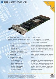
The <strong><strong>PCI</strong>8280</strong> is a high performance standard CPU <strong>PCI</strong> Card. It can be plugged into any<br />
mother board supporting <strong>PCI</strong> standards at 3.3V signalling voltage.<br />
The <strong><strong>PCI</strong>8280</strong> has the following major features on-board:<br />
S3<br />
32-256<br />
MByte<br />
SDRAM<br />
SoDIMM<br />
FlashPROM<br />
4/8 MByte<br />
<strong><strong>PCI</strong>8280</strong><br />
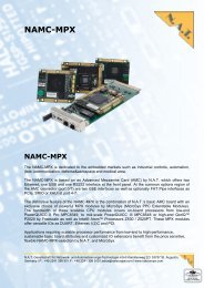
• PowerQUICC II MPC8280 based Embedded PowerPC Architecture<br />
• Front-panel I/O<br />
• 32 bit / 33/66 MHz <strong>PCI</strong> Bus interface Rev. 2.2<br />
• 4 x E1 / T1 / J1 primary rate line interface<br />
• 100BaseT Ethernet channel<br />
• H.100 TSI bus<br />
• 32 – 256 MB main memory (SDRAM)<br />
• 4 – 32 MB FLASH<br />
<strong>PCI</strong><br />
Bus<br />
Figure 1: <strong><strong>PCI</strong>8280</strong> Block Diagram<br />
MPC8265 /<br />
MPC8280<br />
PowerQUICC<br />
266 - 450 MHz<br />
Osz.<br />
60x Bus<br />
Debug<br />
Infineon<br />
QUAD<br />
Falc<br />
E1/T1/J1<br />
H.110<br />
OKI<br />
CT812<br />
Ethernet<br />
10/!00<br />
MBit/s<br />
Filter<br />
Filter<br />
Filter<br />
Filter<br />
E1 / T1 Osz.<br />
Filter<br />
H.100 Bus<br />
Version 1.2 © N.A.T. GmbH 8<br />
S5<br />
S4<br />
S1<br />
S2
1.1 Board Features<br />
• CPU<br />
<strong><strong>PCI</strong>8280</strong> – <strong>Technical</strong> <strong>Reference</strong> <strong>Manual</strong><br />
Depending on the assembled CPU the PowerQUICC II runs with a core clock frequency<br />
of 266 - 450 MHz. The user may choose between a MPC8280 or a MPC8265/8266<br />
CPU (assembly option).<br />
• Memory<br />
SDRAM: The <strong><strong>PCI</strong>8280</strong> provides 32 to 256 MB SDRAM onboard. The SDRAM is<br />
installed as a SODIMM SDRAM module. PC100-type modules of 32<br />
MB, 64 MB, 128 MB, and 256 MB are supported. The SDRAM is 64 bit<br />
wide.<br />
Default: 32 MB installed<br />
Flash PROM: The 16 bit wide Flash PROM provides a capacity of 4 - 32 MB<br />
(assembly option).<br />
• Interfaces<br />
Default: 16 MB installed<br />
<strong>PCI</strong>: The <strong><strong>PCI</strong>8280</strong> includes a 32 bit 33/66 MHz <strong>PCI</strong> bus interface. This is<br />
implemented in the MPC8280 CPU.<br />
H.100/SCSA: The <strong><strong>PCI</strong>8280</strong> implements a 32 bit H.100 interface, which includes a<br />
SCbus interface on I/O-connector S4 according to ECTF specifications.<br />
This is implemented by an OKI ML53812-2 TSI device. In addition, a<br />
user-specific connector S5 is supplied, which carries a subset of the<br />
H.100 interface.<br />
• I/O<br />
E1/T1/J1: The module carries a PEB22554 (QuadFALC) framer, which implements<br />
four E1/T1/J1 interfaces.<br />
Ethernet: The 100 Mbit Ethernet MII interface supplied by the PowerQUICC II is<br />
connected to a 100BaseT interface through a LXT972 framer device.<br />
RS232: There is a RS232 interface available on the <strong><strong>PCI</strong>8280</strong>, connected to the<br />
CPU SMC1 port, sharing a connector with the BDM / JTAG interface<br />
Version 1.2 © N.A.T. GmbH 9
1.2 Board Specification<br />
<strong><strong>PCI</strong>8280</strong> – <strong>Technical</strong> <strong>Reference</strong> <strong>Manual</strong><br />
Table 2: <strong><strong>PCI</strong>8280</strong> Features<br />
Processor PowerQUICC II MPC8280 (333 or 450 MHz) or MPC8265/8266<br />
(266 or 300 MHz) based Embedded PowerPC Architecture<br />
<strong>PCI</strong> Form Factor standard <strong>PCI</strong> short from factor, 32 bit, 3.3V signalling<br />
Front-I/O 4 RJ45 connectors<br />
Main Memory 32 - 256 MByte SDRAM PC100-type<br />
Flash PROM 4 – 32 MByte Flash PROM. On board programmable<br />
Firmware OK1, VxWorks BSP (on request)<br />
Power consumption<br />
(with MPC8265 / 300<br />
MHz)<br />
Environmental<br />
conditions<br />
3.3V 0.85A typ.<br />
5.0V 0.55A typ.<br />
Temperature (operating):<br />
Temperature (storage):<br />
Humidity:<br />
0°C to +60°C with forced cooling<br />
-40°C to +85°C<br />
10 % to 90 % rh noncondensing<br />
Standards compliance <strong>PCI</strong> Rev. 2.2<br />
ECTF H.100 Hardware Compatibility Specification: CT Bus revision<br />
1.0, 1996/97<br />
Note:<br />
The <strong>PCI</strong> bridge within the MPC8280/8265 always drives signals to 3.3V level (3.3V<br />
signalling), but is made 5V tolerant by implementation of voltage-level-translating FET<br />
switches between the <strong>PCI</strong> connector and the MPC8280/8265 <strong>PCI</strong> pins.<br />
Version 1.2 © N.A.T. GmbH 10
2 Installation<br />
2.1 Safety Note<br />
CAUTION<br />
<strong><strong>PCI</strong>8280</strong> – <strong>Technical</strong> <strong>Reference</strong> <strong>Manual</strong><br />
To ensure proper functioning of the <strong><strong>PCI</strong>8280</strong> during its usual lifetime take the<br />
following precautions before handling the board.<br />
Electrostatic discharge and incorrect board installation and uninstallation can<br />
damage circuits or shorten their lifetime.<br />
• Before installing or uninstalling the <strong><strong>PCI</strong>8280</strong> read this installation section<br />
• Before installing or uninstalling the <strong><strong>PCI</strong>8280</strong>, read the Installation Guide<br />
and the User’s <strong>Manual</strong> of the carrier board used<br />
• Before installing or uninstalling the <strong><strong>PCI</strong>8280</strong> on a carrier board or both in a<br />
case:<br />
- Check all installed boards and modules for steps that you have to take<br />
before turning on or off the power.<br />
- Take those steps.<br />
- Finally turn on or off the power.<br />
• Before touching integrated circuits ensure to take all require precautions for<br />
handling electrostatic devices.<br />
• Ensure that the <strong><strong>PCI</strong>8280</strong> is connected to the carrier board via the <strong>PCI</strong><br />
connector and that the power is available (GND, +5V, and +3,3V).<br />
• When operating the board in areas of strong electromagnetic radiation<br />
ensure that the module<br />
- is bolted to the front panel or rack<br />
- and shielded by closed housing<br />
Version 1.2 © N.A.T. GmbH 11
<strong><strong>PCI</strong>8280</strong> – <strong>Technical</strong> <strong>Reference</strong> <strong>Manual</strong><br />
2.2 Installation Prerequisites and Requirements<br />
IMPORTANT<br />
Before powering up<br />
• check this section for installation prerequisites and requirements<br />
2.2.1 Requirements<br />
2.2.2 Power supply<br />
The installation requires only<br />
• a carrier board for connecting the <strong><strong>PCI</strong>8280</strong><br />
• power supply<br />
The power supply for the <strong><strong>PCI</strong>8280</strong> must meet the following specifications:<br />
• required for the module:<br />
- +3,3V / 0.85A typical<br />
- +5,0V / 0.55A typical<br />
2.2.3 Automatic Power Up<br />
In the following situations the <strong><strong>PCI</strong>8280</strong> will automatically be reset and proceed with a<br />
normal power up.<br />
Voltage sensors<br />
The voltage sensor generates a reset<br />
• when +5V voltage level drops below 4,4V *<br />
• when +5V voltage level rises above 5,6V *<br />
• when +3.3V voltage level drops below 2,65V *<br />
• when +3.3V voltage level rises above 3,9V *<br />
• or when the carrier board signals a <strong>PCI</strong> Reset<br />
Watchdog (if enabled)<br />
* defined by: “<strong>PCI</strong> Specification Revision 2.2, Section 4.2.1.1 and Section 4.3.2”<br />
Version 1.2 © N.A.T. GmbH 12
2.3 Location Overview<br />
<strong><strong>PCI</strong>8280</strong> – <strong>Technical</strong> <strong>Reference</strong> <strong>Manual</strong><br />
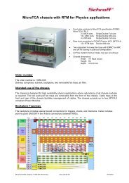
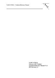
The Figure 2: "Location diagram of the <strong><strong>PCI</strong>8280</strong>" highlights the position of the<br />
important components. Depending on the board type it might be that the board does not<br />
include all components named in the location diagram.<br />
S1<br />
4 E1/T1<br />
R<br />
e<br />
l<br />
a<br />
i<br />
s<br />
Figure 2: Location diagram of the <strong><strong>PCI</strong>8280</strong><br />
T<br />
r<br />
a<br />
f<br />
o<br />
s<br />
Line<br />
Inter-<br />
face<br />
Quad<br />
FALC<br />
Logik<br />
S5<br />
JP1<br />
MPC8265 /<br />
MPC8280<br />
S3 <strong>PCI</strong><br />
CT812<br />
P<br />
o<br />
w<br />
e<br />
r<br />
<strong><strong>PCI</strong>8280</strong> Top Layer<br />
FLASH<br />
SDRAM<br />
SoDIMM<br />
Eth<br />
JP2<br />
S4<br />
S2 Eth<br />
Version 1.2 © N.A.T. GmbH 13
3 Functional Blocks<br />
<strong><strong>PCI</strong>8280</strong> – <strong>Technical</strong> <strong>Reference</strong> <strong>Manual</strong><br />
The <strong><strong>PCI</strong>8280</strong> can be divided into a number of functional blocks, which are described in the<br />
following paragraphs.<br />
3.1 Processor<br />
The MPC8280 PowerQUICC II is a versatile communications processor that integrates on<br />
one chip a high-performance PowerPC RISC microprocessor, a very flexible system<br />
integration unit, and many communications peripheral controllers that can be used in a variety<br />
of applications, particularly in communications and networking systems.<br />
The core is an embedded variant of the PowerPC MPC603e microprocessor with 16 Kbytes<br />
of instruction cache and 16 Kbytes of data cache and no floating-point unit (FPU). The system<br />
interface unit (SIU) consists of a flexible memory controller that interfaces to almost any<br />
user-defined memory system, and many other peripherals making this device a complete<br />
system on a chip.<br />
The communications processor module (CPM) includes four serial communications controllers<br />
(SCCs) , with the addition of three high-performance communication channels that<br />
support new emerging protocols (for example, 155 Mbps ATM and Fast Ethernet). The<br />
MPC8280 has dedicated hardware that can handle up to 256 full-duplex, time-division-multiplexed<br />
logical channels, as well as DMA functionality executing memory to memory and<br />
memory to I/O transfers.<br />
3.2 <strong>PCI</strong> Interface<br />
The MPC8280 integrates a standard 32 bit, 33/66 MHz <strong>PCI</strong> interface, compliant to <strong>PCI</strong><br />
Specification Rev. 2.2.<br />
Version 1.2 © N.A.T. GmbH 14
3.3 Memory<br />
3.3.1 SDRAM<br />
<strong><strong>PCI</strong>8280</strong> – <strong>Technical</strong> <strong>Reference</strong> <strong>Manual</strong><br />
As the onboard SDRAM memory has to be accessed not only be the CPU, but also by the host<br />
trough the <strong>PCI</strong> bridge, external address latches and multiplexers had to be implemented. The<br />
structure is shown in Figure 3: below.<br />
Figure 3: Address / Data Paths to onboard Devices<br />
MPC<br />
8280<br />
PD22<br />
PD23<br />
Addr.<br />
64 bit Data<br />
Address<br />
Latch,<br />
SDRAM<br />
MUX<br />
SDRAM Control<br />
DRTYPEx<br />
SDRAM Addr.<br />
latched Adress<br />
SDRAM<br />
SODIMM<br />
<strong>Module</strong><br />
other<br />
Devices<br />
The SDRAM is connected to the 60x bus interface of the MPC8280. The multiplexer organisation<br />
can be adjusted to different SDRAM types by the DRTYPEx selection signals. Suitable<br />
SDRAM modules must be of PC100 or PC133 type. Refer to Chapter 4, Table 9: and Table<br />
10: for further information on SODIMM modules.<br />
Version 1.2 © N.A.T. GmbH 15
3.3.2 FLASH<br />
<strong><strong>PCI</strong>8280</strong> – <strong>Technical</strong> <strong>Reference</strong> <strong>Manual</strong><br />
FLASH memory is connected to the upper 16 data bits D0 – 15 and to the latched address<br />
lines. The FLASH on the <strong><strong>PCI</strong>8280</strong> can be programmed either by the CPU (by appropriate<br />
software or through the BDM port) or by a <strong>PCI</strong> bus master. In the latter case the<br />
PowerQUICC II has to be prevented from booting from FLASH while it does not contain a<br />
defined boot program, in order not to enter unknown states. This can be achieved by setting a<br />
DIL switch (SW1), which disables the MPC8280 CPU core after the following Power-Up<br />
cycle. This feature is used for programming the FLASH memory on the <strong><strong>PCI</strong>8280</strong> via the <strong>PCI</strong><br />
bus. If swich no. 1 of SW1 is set to ‘ON’ the Hardware Configuration Words for the CPU are<br />
loaded from an onboard CPLD. Some basic register setup is performed using the ‘Autoload’<br />
function of the MPC8280. Once the FLASH has been programmed, SW1 / 1 has to be set to<br />
‘OFF’ again. If the FLASH contains valid boot code, it may be reprogrammed without having<br />
to use SW1. Programming software is available on request. Please refer to section 5.4 for<br />
details on DIL switch SW1, and to section 6.1 for details on the Hardware Configuration<br />
Words.<br />
3.3.3 I 2 C Devices<br />
There are two I 2 C devices on the <strong><strong>PCI</strong>8280</strong>, which are connected to the MPC8280 I 2 C bus; an<br />
EEPROM used for storage of board-specific information, and the EEPROM on the SODIMM<br />
SDRAM module, which contains vital data about the SDRAM module size and address<br />
organisation. This information is necessary, in order to be able to program the SDRAM<br />
controller functions appropriately. The EEPROM on the SODIMM typically defaults to a<br />
24C02 type, the EEPROM for storage of board-specific information defaults to a 24C08<br />
device. The address of the EEPROM on the SDRAM SODIMM module is 0x0, the address of<br />
the other EEPROM is 0x4.<br />
Version 1.2 © N.A.T. GmbH 16
<strong><strong>PCI</strong>8280</strong> – <strong>Technical</strong> <strong>Reference</strong> <strong>Manual</strong><br />
3.4 H.100 Bus Controller and Line Interfaces<br />
3.4.1 Block Diagramm of the TDM Structure<br />
Figure 4: Local TDM Bus Organisation and Synchronisation<br />
MPC<br />
8265<br />
/<br />
MPC<br />
8280<br />
PA0<br />
LDO[0-7]<br />
LDI[0-7]<br />
LDI[0-3]<br />
L_CLK[0-1], L_FS[0-1]<br />
LDO[0-3]<br />
3.4.2 Description of the TDM Structure<br />
LREF[0-3]<br />
L_CLK[0], L_FS[0]<br />
OKI<br />
TSI<br />
Quad<br />
FALC<br />
The TDM data are routed through the ML53812-2 TSI device. Hence, any timeslot switching<br />
between H.110 bus, framers, and CPU is possible. Local TDM data lines LDI[0 – 3] and<br />
LDO[0 – 3] are routed between QuadFALC and TSI and CPU. In order to prevent data<br />
distortion the data outputs of the QuadFALC may be isolated from the TDM bus, if all 8<br />
TDM lines are to be used between TSI and CPU. The switch element connecting the<br />
QuadFALC data lines LDI[0 – 3] is enabled by programming CPU port pin PA0. Default:<br />
PA0 = 1, QuadFALC data lines LDI[0 – 3] enabled.<br />
The connection between the TDM data lines LDI[0 – 7] / LDO[0 – 7] and the corresponding<br />
TDM channels of the MPC8260 is shown in the following table:<br />
Version 1.2 © N.A.T. GmbH 17<br />
H.<br />
1<br />
1<br />
0<br />
L<br />
i<br />
n<br />
e
<strong><strong>PCI</strong>8280</strong> – <strong>Technical</strong> <strong>Reference</strong> <strong>Manual</strong><br />
Table 3: TDM Channel �� LDI/O Data Line Connection<br />
MPC8260<br />
TDM<br />
Channel<br />
TDM data<br />
line<br />
LDIx/LDOx<br />
Sync for<br />
TDM<br />
Channel<br />
Clock for<br />
TDM<br />
Channel<br />
TDM_A1 LDI/O[4] L_FS0 L_CLK0<br />
TDM_B1 LDI/O[5] L_FS0 L_CLK0<br />
TDM_C1 LDI/O[6] L_FS0 L_CLK0<br />
TDM_D1 LDI/O[7] L_FS0 L_CLK0<br />
TDM_A2 LDI/O[0] L_FS1 L_CLK1<br />
TDM_B2 LDI/O[1] L_FS1 L_CLK1<br />
TDM_C2 LDI/O[2] L_FS1 L_CLK1<br />
TDM_D2 LDI/O[3] L_FS1 L_CLK1<br />
The Sync and Clock signals L_FS[0-1] and L_CLK[0-1] can be programmed within the OKI<br />
TSI local clock and local sync settings.<br />
The TSI device derives its time base from one of the LREF signals coming from the framers,<br />
or from the H.110 bus. From this input it generates local clock and frame sync for the framers<br />
and the CPU to synchronize to. Timing reference for offboard routing devices can be provided<br />
by programming one of the local LREF signals to be output on one of the NETREFx signals.<br />
For detailed information please refer to the Motorola MPC8260, OKI ML53812-2, and<br />
Infineon PEB22554 User’s <strong>Manual</strong>s.<br />
Version 1.2 © N.A.T. GmbH 18
3.4.3 H.100 Bus Compatibility<br />
<strong><strong>PCI</strong>8280</strong> – <strong>Technical</strong> <strong>Reference</strong> <strong>Manual</strong><br />
The H.100 bus implemented on the <strong><strong>PCI</strong>8280</strong> may be used to interconnect with other boards in<br />
the system either supporting H.100 or SCbus. SCbus data lines correspond to H.100 data lines<br />
CT_D0 – 15. See chapters 5.8 and 5.9 (H.100 connectors) for reference.<br />
3.4.4 E1/T1/J1 Line Interfaces<br />
The four E1/T1/J1 interfaces connect the Infineon QuadFALC framer to the front panel RJ45<br />
connector S1. Timing and interface characteristics can be set up by software within the<br />
QuadFALC, the correct line impedance is selected by programming the IMPSELA to<br />
IMPSELC port signals as described below in chapter 4.2.1.1. The line interfaces conform to<br />
EN60950 and G.703.<br />
3.5 Ethernet<br />
The LXT972 Ethernet LIU is connected to the MPC8280 through the MII interface. It<br />
connects to the front panel connector S3.<br />
Configuration settings of the LXT972 are done by MPC8280 port pins. This applies to signals<br />
TxSLEWx, PAUSE, and PWRDWN. Refer to Table 8: for details. ADDR0 is grounded.<br />
Version 1.2 © N.A.T. GmbH 19
4 Hardware<br />
4.1 Memory Map<br />
<strong><strong>PCI</strong>8280</strong> – <strong>Technical</strong> <strong>Reference</strong> <strong>Manual</strong><br />
All addresses are set up by programming the corresponding Chip-Select Decoder of the<br />
PowerQUICC.<br />
Table 4: Memory Map<br />
Device CS<br />
Line<br />
Address Function Notes<br />
main FLASH CS0 programmable Boot, user code 4/8/16/32 MByte Flash-Prom<br />
(16 bit wide)<br />
not used CS1 programmable not used<br />
SDRAM CS2 programmable main memory, 32 - 256 MByte SDRAM<br />
CS2 and CS3 (64 bit wide)<br />
SDRAM CS3 programmable share the same<br />
SODIMM<br />
Register CS4 programmable PCB version,<br />
I/O setup, reset<br />
8 bit wide<br />
ML53812 CS5 programmable H.100 TSI 8 bit wide<br />
PEB22554 CS6 programmable QuadFALC 8 bit wide<br />
not used CS7 not used<br />
not used CS8 not used<br />
not used CS9 not used<br />
not used CS10 not used<br />
not used CS11 not used<br />
Version 1.2 © N.A.T. GmbH 20
<strong><strong>PCI</strong>8280</strong> – <strong>Technical</strong> <strong>Reference</strong> <strong>Manual</strong><br />
4.2 Definition of PowerQUICC II Port Pins<br />
PowerQUICC II port pins are used to communicate with the framers and to set up some board<br />
configuration. In detail:<br />
Table 5: PowerQUICC II Port Pin Usage (Port A)<br />
Signal Function PowerQUICC II Port A Pin Description<br />
Ethernet MII COL PA31 MII interface to the 100 Mbit<br />
transceiver LXT972<br />
Ethernet MII CRS PA30 MII interface<br />
Ethernet MII TX ER PA29 MII interface<br />
Ethernet MII TX EN PA28 MII interface<br />
Ethernet MII RX DV PA27 MII interface<br />
Ethernet MII RX ER PA26 MII interface<br />
Ethernet MII MDC PA25 MII interface<br />
Ethernet MII MDIO PA24 MII interface<br />
PA23<br />
PA22<br />
Ethernet MII TXD3 PA21 MII interface<br />
Ethernet MII TXD2 PA20 MII interface<br />
Ethernet MII TXD1 PA19 MII interface<br />
Ethernet MII TXD0 PA18 MII interface<br />
Ethernet MII RXD3 PA17 MII interface<br />
Ethernet MII RXD2 PA16 MII interface<br />
Ethernet MII RXD1 PA15 MII interface<br />
Ethernet MII RXD0 PA14 MII interface<br />
PA13<br />
PA12<br />
PA11<br />
PA10<br />
TSI LDI4 PA9 Time Slot Assigner Bus data bit 4,<br />
output of the MPC8280, input to<br />
the ML53812 H.100 controller<br />
(Time Slot Interchange (TSI))<br />
TSI LDO4 PA8 Time Slot Assigner Bus data bit 4,<br />
input to the MPC8280, output of<br />
the ML53812 H.100 controller<br />
(Time Slot Interchange (TSI))<br />
TSI L_FS PA7 Time Slot Assigner frame sync,<br />
input to the MPC8280, output of<br />
the ML53812 H.100 controller<br />
TSI L_FS PA6 TSA frame sync<br />
PA5<br />
PA4<br />
Version 1.2 © N.A.T. GmbH 21
<strong><strong>PCI</strong>8280</strong> – <strong>Technical</strong> <strong>Reference</strong> <strong>Manual</strong><br />
TSI L_CLK1 PA3 Time Slot Assigner alternate<br />
clock, input to the MPC8280,<br />
output of the ML53812 H.100<br />
controller<br />
TSI L_CLK1 PA2 TSA alternate clock<br />
PA1<br />
LDO_F_EN* PA0 enable TDM data lines between<br />
QuadFALC and CPU<br />
Table 6: PowerQUICC II Port Pin Usage (Port B)<br />
Signal Function PowerQUICC II Port B Pin Description<br />
TSI LDI1 PB31 TSA data bus bit 1, TSI in<br />
TSI LDO1 PB30 TSA data bus bit 1, TSI out<br />
TSI L_FS1 PB29 TSA alternate frame sync<br />
TSI L_FS1 PB28 TSA alternate frame sync<br />
TSI LDI2 PB27 TSA data bus bit 2, TSI in<br />
TSI LDO2 PB26 TSA data bus bit 2, TSI out<br />
TSI L_FS1 PB25 TSA alternate frame sync<br />
TSI L_FS1 PB24 TSA alternate frame sync<br />
TSI LDI3 PB23 TSA data bus bit 3, TSI in<br />
TSI LDO3 PB22 TSA data bus bit 3, TSI out<br />
TSI L_FS1 PB21 TSA alternate frame sync<br />
TSI L_FS1 PB20 TSA alternate frame sync<br />
PB19<br />
PB18<br />
TSI L_CLK1 PB17 TSA alternate clock<br />
TSI L_CLK1 PB16 TSA alternate clock<br />
TSI LDI6 PB15 TSA data bus bit 6, TSI in<br />
TSI LDO6 PB14 TSA data bus bit 6, TSI out<br />
TSI L_FS PB13 TSA frame sync<br />
TSI L_FS PB12 TSA frame sync<br />
TSI LDI7 PB11 TSA data bus bit 7, TSI in<br />
TSI LDO7 PB10 TSA data bus bit 7, TSI out<br />
TSI L_FS PB9 TSA frame sync<br />
TSI L_FS PB8 TSA frame sync<br />
TSI LDI0 PB7 TSA data bus bit 0, TSI in<br />
TSI LDO0 PB6 TSA data bus bit 0, TSI out<br />
TSI L_FS1 PB5 TSA alternate frame sync<br />
TSI L_FS1 PB4 TSA alternate frame sync<br />
Version 1.2 © N.A.T. GmbH 22
<strong><strong>PCI</strong>8280</strong> – <strong>Technical</strong> <strong>Reference</strong> <strong>Manual</strong><br />
Table 7: PowerQUICC II Port Pin Usage (Port C)<br />
Signal Function PowerQUICC II Port C Pin Description<br />
TSI L_CLK PC31 Time Slot Assigner clock,<br />
input to the MPC8280, output<br />
of the ML53812 H.100<br />
controller<br />
TSI L_CLK PC30 TSA clock<br />
TSI L_CLK PC29 TSA clock<br />
TSI L_CLK PC28 TSA clock<br />
TSI L_CLK PC27 TSA clock<br />
TSI L_CLK PC26 TSA clock<br />
TSI L_CLK PC25 TSA clock<br />
TSI L_CLK PC24 TSA clock<br />
internal PC23 do not use<br />
Ethernet MII TXCLK PC22 MII interface<br />
MC_CLK* PC21 Message Channel clock,<br />
H.100 bus<br />
Ethernet MII RXCLK PC20 MII interface<br />
TSI L_CLK1 PC19 Time Slot Assigner alternate<br />
clock, input to the MPC8280,<br />
output of the ML53812 H.100<br />
controller<br />
TSI L_CLK1 PC18 TSA alternate clock<br />
TSI L_CLK1 PC17 TSA alternate clock<br />
TSI L_CLK1 PC16 TSA alternate clock<br />
PC15<br />
MC_RXD* PC14 Message Channel Receive,<br />
H.100 bus<br />
PC13<br />
PC12<br />
PC11<br />
IMPSELA* PC10 E1/T1/J1 Receive Interface<br />
Impedance Select<br />
IMPSELB* PC9 E1/T1/J1 Receive Interface<br />
Impedance Select<br />
IMPSELC* PC8 E1/T1/J1 Transmit Interface<br />
Impedance Select<br />
LED7* PC7 Front Panel LED 7<br />
LED8* PC6 Front Panel LED 8<br />
LED6* PC5 Front Panel LED 6<br />
LED5* PC4 Front Panel LED 5<br />
LED4* PC3 Front Panel LED 4<br />
LED3* PC2 Front Panel LED 3<br />
LED2* PC1 Front Panel LED 2<br />
LED1* PC0 Front Panel LED 1<br />
Version 1.2 © N.A.T. GmbH 23
<strong><strong>PCI</strong>8280</strong> – <strong>Technical</strong> <strong>Reference</strong> <strong>Manual</strong><br />
Table 8: PowerQUICC II Port Pin Usage (Port D)<br />
Signal Function PowerQUICC II Port D Pin Description<br />
MC_RXD* PD31 Message Channel Receive,<br />
H.100 bus<br />
MC_TXD* PD30 Message Channel Transmit,<br />
H.100 bus<br />
PAUSE* PD29 LXT972 control function<br />
reserved PD28 do not use<br />
TxSL1* PD27 LXT972 control function<br />
TxSL0* PD26 LXT972 control function<br />
PD25<br />
PWRDN* PD24 LXT972 control function<br />
DRTYPE0* PD23 SDRAM control function<br />
DRTYPE1* PD22 SDRAM control function<br />
PD21<br />
PD20<br />
PD19<br />
PD18<br />
PD17<br />
PD16<br />
SDA_PQ* PD15 I 2 C Bus, data<br />
SCL_PQ* PD14 I 2 C Bus, clock<br />
TSI LDI5 PD13 TSA data bus bit 5, TSI in<br />
TSI LDO5 PD12 TSA data bus bit 5, TSI out<br />
TSI L_FS PD11 TSA frame sync<br />
TSI L_FS PD10 TSA frame sync<br />
TXD1_SMC* PD9 transmit data lines of the<br />
RS232 interface, SMC1<br />
RXD1_SMC* PD8 receive data lines of the<br />
RS232 interface, SMC1<br />
PD7<br />
PD6<br />
PD5<br />
PD4<br />
Signals with asterisk (*) are described in detail below.<br />
Version 1.2 © N.A.T. GmbH 24
4.2.1 Signal Description<br />
<strong><strong>PCI</strong>8280</strong> – <strong>Technical</strong> <strong>Reference</strong> <strong>Manual</strong><br />
Port pins without signal name and description are not connected and should be programmed<br />
as outputs.<br />
4.2.1.1 Selecting the TDM Data Path for LD0 - 3<br />
LDO_F_EN enables TDM data lines 0 – 3 between QuadFALC and CPU<br />
LDO_F_EN = 1: TDM data lines 0 – 3 between QuadFALC and CPU are<br />
enabled, TDM data lines 4 – 7 may be used between<br />
CPU and OKI TSI (default)<br />
LDO_F_EN = 0: TDM data lines 0 – 3 between QuadFALC and CPU are<br />
disabled, TDM data lines 0 – 7 may be used between<br />
CPU and OKI TSI<br />
Note: This feature is available only from HW release 1.1 up.<br />
4.2.1.2 Selecting the ISDN Line Impedance<br />
IMPSELA, Line impedance select lines used for selection of 100 Ω (T1), 110 Ω (J1),<br />
IMPSELB 120 Ω (E1), or 75 Ω (E1) receiver line termination<br />
IMPSELA IMPSELB receiver line termination<br />
0 0 100 Ω (T1)<br />
0 1 75 Ω (E1)<br />
1 0 120 Ω (E1) (default)<br />
1 1 110 Ω (J1)<br />
IMPSELC transmitter line termination<br />
IMPSELC transmitter line termination<br />
0 2 Ω (T1/J1)<br />
1 7.5 Ω (E1) (default)<br />
The FET switches used for hardware selection of transmitter line<br />
termination are not assembled by default; transmitter line termination is<br />
performed by software. In case transmitter line termination by hardware is<br />
requested, contact N.A.T. for this assembly option. For both ways of<br />
transmitter line termination different driver software is needed.<br />
Default: programming of IMPSELC has no effect<br />
Version 1.2 © N.A.T. GmbH 25
<strong><strong>PCI</strong>8280</strong> – <strong>Technical</strong> <strong>Reference</strong> <strong>Manual</strong><br />
4.2.1.3 H.100 Message Channel Interface Pins<br />
MC_RXD receive data line of the RS232 interface, SCC1 on PD31<br />
MC_TXD transmit data line of the RS232 interface, SCC1 on PD30<br />
MC_RXD receive data line of the RS232 interface, SCC1 /CD on PC14<br />
MC_CLK clock line of the RS232 interface, BRG6 on PC21<br />
4.2.1.4 Serial Line Interface Pins<br />
RXD1_SMC receive data line of the RS232 interface, SMC1 on PD8<br />
TXD1_SMC transmit data line of the RS232 interface, SMC1 on PD9<br />
4.2.1.5 I 2 C Interface Pins<br />
SDA_PQ, I 2 C interface connected to the SDRAM SODIMM EEPROM (address 0x0)<br />
SCL_PQ and to the general purpose EEPROM U10 (24C02, address 0x4)<br />
4.2.1.6 100BaseT Configuration<br />
TxSL0, TxSL1, Port pins used for LXT972 control functions. Please refer to the LXT972<br />
users manual for details. Possible settings are:<br />
TxSLEW1 TxSLEW0 slew rate (rise and fall time)<br />
0 0 2.5 ns<br />
0 1 3.1 ns<br />
1 0 3.7 ns<br />
1 1 4.3 ns (default)<br />
PAUSE Port pin used for LXT972 control functions. Please refer to the LXT972<br />
users manual for details.<br />
Pause = 1: Pause capabilities during negotiation enabled (default)<br />
PWRDN Port pin used for LXT972 control functions. Please refer to the LXT972<br />
users manual for details.<br />
PWRDWN = 1: Power Down mode selected (default)<br />
4.2.1.7 LED Control Pins<br />
LED1– LED8 Port pins used to control the front panel LEDs 1 – 8. Setting a port pin low<br />
(PCx = 0) turns the respective LED on, setting it high (PCx = 1) turns the<br />
respective LED off (default).<br />
Version 1.2 © N.A.T. GmbH 26
4.2.1.8 SDRAM Configuration Pins<br />
<strong><strong>PCI</strong>8280</strong> – <strong>Technical</strong> <strong>Reference</strong> <strong>Manual</strong><br />
DRTYPE0, Port pins used to set the correct multiplexing logic within Lattice U13.<br />
DRTYPE1 These pins code the size and array information of the SDRAM module<br />
installed. The correct binary value for DRTYPE1-0 has to be determined<br />
by reading the SDRAM SODIMM EEPROM contents. This EEPROM<br />
contains also further information needed to program the SDRAM controller<br />
of the MPC8280 appropriately, e.g. row start address and clock cycles<br />
needed for SDRAM access.<br />
DRTYPEx settings refer to following SODIMM organisation:<br />
Table 9: Supported SDRAM SODIMM <strong>Module</strong> Types<br />
DRTYPE1<br />
(PD22)<br />
DRTYPE0<br />
(PD23)<br />
highest<br />
column<br />
address to be<br />
multiplexed<br />
no. of<br />
SDRAM<br />
column<br />
addresses<br />
0 0 SDA7 8<br />
0 1 SDA8 9<br />
1 0 SDA9 10<br />
1 1 SDA11 11<br />
SDAx refers to SDRAM SODIMM address pin.<br />
Addresses to be programmed to be output on PowerQUICC II signals<br />
BNKSELx:<br />
Table 10: BNKSELx Programming<br />
DRTYPE1 DRTYPE0 BNKSEL2 BNKSEL1<br />
(PD22) (PD23)<br />
0 0 PB_A19 PB_A20<br />
0 1 PB_A18 PB_A19<br />
1 0 PB_A17 PB_A18<br />
1 1 PB_A16 PB_A17<br />
PB_Ax refers to PowerQUICC II address line Ax. BNKSEL0 is not used.<br />
Refer to chapter 6.3 of this manual and to the MPC8280 User’s <strong>Manual</strong> for<br />
a detailed description of how to program the Memory Controller of the<br />
MPC8280.<br />
Version 1.2 © N.A.T. GmbH 27
4.3 Interrupt Structure<br />
<strong><strong>PCI</strong>8280</strong> – <strong>Technical</strong> <strong>Reference</strong> <strong>Manual</strong><br />
The <strong><strong>PCI</strong>8280</strong> has the following Interrupt structure:<br />
Interrupt source<br />
Table 11: Interrupt Structure<br />
PowerQUICC Interrupt level<br />
NC IRQ-Level 0 (highest level)<br />
NC IRQ-Level 1<br />
ML53812 IRQ-Level 2<br />
PEB22554 IRQ-Level 3<br />
LXT972 IRQ-Level 4<br />
NC IRQ-Level 5<br />
NC IRQ-Level 6<br />
NC IRQ-Level 7 (lowest level)<br />
4.4 CPU - PLL-Setup<br />
The basic setting of the clocks is done by pulling the MODCK pins during /CPURST.<br />
/CPURST is the Reset input of the CPU and valid with Power-On RESET and /<strong>PCI</strong>RST.<br />
These are programmable through CPLD U13 (BA0-2). There are 5 additional pins<br />
(<strong>PCI</strong>MODCKx) responsible for setting the PLLs, which are also read during /PORESET. E.g.<br />
the default PLL setting for a MPC8265 CPU is MODCK1 - 3 = 100b and PMODCKH0 - 3 =<br />
0100b for a 300/200 MHz CPU/CPM version, the default PLL setting for a MPC8280 CPU is<br />
MODCK1 - 3 = 100b and PMODCKH0 - 3 = 1010b for a 400/266 MHz CPU/CPM version.<br />
Whether the <strong>PCI</strong> clock frequency is interpreted as 33 MHz or 66 MHz depends on the status<br />
of the PMC /M66EN signal during /HRESET.<br />
Version 1.2 © N.A.T. GmbH 28
4.5 Register<br />
4.5.1 PCB Revision Register<br />
<strong><strong>PCI</strong>8280</strong> – <strong>Technical</strong> <strong>Reference</strong> <strong>Manual</strong><br />
There is an 8 bit wide PCB revision register implemented in the CPLD onboard the <strong><strong>PCI</strong>8280</strong>,<br />
which contains the revision code of the PCB. This code reads decimally-coded in 2 nibbles,<br />
i.e. the PCB version V1.0 reads 0x10. The register is addressed by the Register Chip Select<br />
CS4 as described in Table 4: with address offset 0x0.<br />
4.5.2 I/O Register<br />
There is an 8 bit wide I/O register implemented in the CPLD onboard the <strong><strong>PCI</strong>8280</strong>, which<br />
serves 3 functions:<br />
- software reset (reboot) functionality of the MPC8280 CPU, transformed by<br />
logic into a hardware reset to the CPU<br />
- software reset of all I/O devices (QuadFALC, OKI TSI, Ethernet PHY)<br />
- selection of E1 or T1/J1 functionality for the QuadFALC, resulting in an<br />
appropriate MCLK (2.048 or 1.544 MHz) provided<br />
The I/O register base address is programmed by the settings for CS4. The register is 8 bits<br />
wide, read/write, but only 3 bits are used, the rest reads as 0.<br />
Bit Number<br />
Table 12: I/O Register<br />
Read/Write Status Information / Control Setting<br />
Bit 7 W 1 = reset for the MPC8280 CPU, defaults to 0<br />
Bit 6 R not used<br />
Bit 5 R not used<br />
Bit 4 R not used<br />
Bit 3 R not used<br />
Bit 2 R not used<br />
Bit 1 R/W selection of E1 or T1/J1 functionality for the QFALC<br />
0 = E1 (default), 1 = T1/J1<br />
Bit 0 R/W 1 = reset for all I/O devices, defaults to 0<br />
The register is addressed by the Register Chip Select CS4 as described in Table 4: with<br />
address offset 0x10.<br />
Version 1.2 © N.A.T. GmbH 29
4.6 Front Panel and LEDs<br />
<strong><strong>PCI</strong>8280</strong> – <strong>Technical</strong> <strong>Reference</strong> <strong>Manual</strong><br />
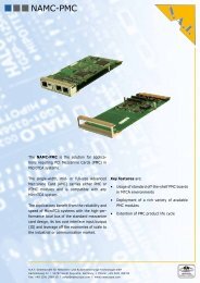
The <strong><strong>PCI</strong>8280</strong> module is equipped with 8 LEDs, which are completely software<br />
programmable.<br />
LED 1<br />
LED 2<br />
LED 3<br />
LED 4<br />
LED 5<br />
LED 6<br />
LED 7<br />
LED 8<br />
N.A.T.<br />
<strong><strong>PCI</strong>8280</strong><br />
E1/T1/J1<br />
LINE 1<br />
E1/T1/J1<br />
LINE 2<br />
E1/T1/J1<br />
LINE 3<br />
E1/T1/J1<br />
LINE 4<br />
Figure 5: Front Panel and LEDs<br />
LEDs:<br />
4.7 Relais in the Line Interface<br />
LED 1 - 8 the green LEDs 1 – 8 are fully software<br />
programmable and their meaning depends<br />
on user application.<br />
Connectors:<br />
LINE 1 - 4 These RJ45 connectors carry<br />
the 4 E1/T1/J1 interfaces.<br />
Please refer to Chapter 5.5 for details on front panel<br />
connectors.<br />
The <strong><strong>PCI</strong>8280</strong> module is equipped with Relais, which short the connectors of line interfaces 1<br />
and 2, and line interfaces 3 and 4 in case of loss of power. Receive lines of line interface 1 are<br />
connected to transmit lines of line interface 2, and vice versa. The same applies for line<br />
interfaces 3 and 4.<br />
When the board is powered up, the relais cut the connection between the connectors and the<br />
receive/transmit lines are connected to the transformers of the respective line interfaces.<br />
Version 1.2 © N.A.T. GmbH 30
5 Connectors<br />
5.1 Connector Overview<br />
S1<br />
4 E1/T1<br />
<strong><strong>PCI</strong>8280</strong> – <strong>Technical</strong> <strong>Reference</strong> <strong>Manual</strong><br />
Figure 6: Connectors of the <strong><strong>PCI</strong>8280</strong><br />
SW1<br />
S5<br />
JP1<br />
S3 <strong>PCI</strong><br />
<strong><strong>PCI</strong>8280</strong> Top Layer<br />
Please refer to the following tables to look up the pin assignment of the <strong><strong>PCI</strong>8280</strong>.<br />
JP2<br />
S4<br />
S2 Eth<br />
Version 1.2 © N.A.T. GmbH 31
<strong><strong>PCI</strong>8280</strong> – <strong>Technical</strong> <strong>Reference</strong> <strong>Manual</strong><br />
5.2 Connector JP1: BDM and JTAG connector<br />
The RS232 serial I/O port is available via a 20 pin SMD micro connector together with the<br />
JTAG / development Port / BDM Port (see JP1 in the location overview).<br />
The RS232 port is realised with the PowerQUICC serial communication controller SMC1.<br />
Table 13: Development Port / BDM and IEEE 1149.1 Connector Pinout<br />
TDO TDO 1<br />
JTAG<br />
BDM Port<br />
PIN<br />
2 /QACK<br />
TDI TDI 3 4 /TRST /TRST<br />
/QREQ 5 JP1 6 +3.3V<br />
TCK TCK 7 8 nc<br />
TMS TMS 9 10 nc<br />
/SRESET 11 12 GND<br />
/HRESET 13 14 nc<br />
/CHKSTOP 15 16 GND<br />
_OUT<br />
RxD_SMC1 17 18 GND<br />
TxD_SMC1 19 20 GND<br />
The BDM port (also called COP header) can be used for debugging. It is supported by major<br />
debug tool manufactorers.<br />
An adapter board with cable plugging into the 20 pin SMD micro connector is available from<br />
N.A.T., that connects the JP1 connector to a standard 2-row, 16-pin, 100mil male header used<br />
for BDM tool boxes, and routes the additional RS232 debug port signals to a standard 9-pin<br />
SubD female connector.<br />
Version 1.2 © N.A.T. GmbH 32
<strong><strong>PCI</strong>8280</strong> – <strong>Technical</strong> <strong>Reference</strong> <strong>Manual</strong><br />
5.3 Connector JP2: Lattice programming port<br />
Connector JP2 connects the JTAG- or programming-port of the Lattice CPLD devices. The<br />
CPLD devices are connected to a TDI – TDO daisy-chain.<br />
Table 14: Lattice programming port<br />
Pin No.<br />
Signal Signal Pin No.<br />
1 TCK nc 2<br />
3 TMS GND 4<br />
5 TDI +3.3V 6<br />
7 TDO GND 8<br />
9 /TRST nc 10<br />
5.4 DIL Switch SW1: FLASH Programming Enable Switch<br />
During normal operation the FLASH may be (re)programmed any time by the MPC8280.<br />
Only in case the FLASH image has been corrupted the following programming procedure<br />
applies:<br />
The FLASH programming mode is chosen by switching switch no. 1 of DIL switch SW1 to<br />
ON and powering up the module. This mode is to be used in order to program a completely<br />
empty or corrupted FLASH device. The MPC8280 will read the configuration word from a<br />
CPLD device and come up in Core Disabled Mode, and the FLASH will be visible in the<br />
window programmed in the MPC8280 from <strong>PCI</strong> to 60x bus. On the <strong>PCI</strong> bus 2 windows will<br />
be defined within the MPC8280 in core disabled mode, both requesting 128KB of memory<br />
space. After having programmed the FLASH, the switch has to be set to OFF again and power<br />
needs to be cycled for the CPU to come out of Power-On-Reset with core enabled. Sample<br />
code is available on request.<br />
Version 1.2 © N.A.T. GmbH 33
<strong><strong>PCI</strong>8280</strong> – <strong>Technical</strong> <strong>Reference</strong> <strong>Manual</strong><br />
5.5 The Front Panel Connector S1<br />
The front panel connectors are 8-pin RJ45 connectors. The 4 E1/T1/J1 line interfaces are<br />
available on the pins of the front panel connectors S1. Table 15: shows the pin assignment.<br />
Table 15: Pin Assignment of the Front-panel Connectors S1 (ISDN)<br />
Pin No.<br />
Signal Signal Pin No.<br />
1 RX+ RX- 2<br />
3 nc TX+ 4<br />
5 TX- nc 6<br />
7 nc nc 8<br />
This pinning is valid for all 4 ports of S1.<br />
5.6 Ethernet Connector S2<br />
Table 16: shows the pin assignment of RJ45-connector S2. This connector carries the<br />
100BaseT signals of the Ethernet interface. Term. is the 100BaseT termination used for pins<br />
4, 5, 7, and 8.<br />
Table 16: Pin Assignment of Connector (Ethernet)<br />
Pin No.<br />
5.7 <strong>PCI</strong> Connector S3<br />
Signal Signal Pin No.<br />
1 TX+ TX- 2<br />
3 RX+ Term. 4<br />
5 Term. RX- 6<br />
7 Term. Term. 8<br />
<strong>PCI</strong> connector S3 carries the standard PC <strong>PCI</strong> pin/finger assignment, which is specified in the<br />
<strong>PCI</strong> Specification Rev. 2.2.<br />
Pins for +12V, –12V and V(I/O) are not connected to the module. The same applies to JTAG<br />
signals TCK, TMS, and /TRST, and <strong>PCI</strong> signals /LOCK, /REQ64, /ACK64, /SDONE, /SBO,<br />
/INTB, /INTC, /INTD.<br />
The <strong>PCI</strong> bridge within the MPC8280 always drives signals to 3.3V level, and is not 5V<br />
tolerant.<br />
Version 1.2 © N.A.T. GmbH 34
<strong><strong>PCI</strong>8280</strong> – <strong>Technical</strong> <strong>Reference</strong> <strong>Manual</strong><br />
5.8 Complete H.100 Implementation on Edge Connector S4<br />
Table 17: Complete H.100 Implementation on Edge Connector S4<br />
Finger No.<br />
Signal Signal Finger No.<br />
1 nc +5V 2<br />
3 CT_D31 CT_D30 4<br />
5 CT_D29 CT_D28 6<br />
7 GND CT_D27 8<br />
9 CT_D26 CT_D25 10<br />
11 CT_D24 GND 12<br />
13 CT_D23 CT_D22 14<br />
15 CT_D21 CT_D20 16<br />
17 GND CT_D19 18<br />
19 CT_D18 CT_D17 20<br />
21 CT_D16 GND 22<br />
23 CT_D15 CT_D14 24<br />
25 CT_D13 CT_D12 26<br />
27 GND CT_D11 28<br />
29 CT_D10 CT_D9 30<br />
31 CT_D8 GND 32<br />
33 CT_D7 CT_D6 34<br />
35 CT_D5 CT_D4 36<br />
37 GND CT_D3 38<br />
39 CT_D2 CT_D1 40<br />
41 CT_D0 GND 42<br />
43 /CT_FRAME_A GND 44<br />
45 CT_C8_A GND 46<br />
47 CT_NETREF GND 48<br />
49 /CT_FRAME_B GND 50<br />
51 CT_C8_B GND 52<br />
53 CT_MC GND 54<br />
55 /FR_COMP GND 56<br />
57 SCLK GND 58<br />
59 SCLKx2 GND 60<br />
61 C2 GND 62<br />
63 /C4 GND 64<br />
65 /C16+ /C16- 66<br />
67 GND nc 68<br />
Version 1.2 © N.A.T. GmbH 35
<strong><strong>PCI</strong>8280</strong> – <strong>Technical</strong> <strong>Reference</strong> <strong>Manual</strong><br />
5.9 16-pin male Header S5 for partial H.100 Connection<br />
Table 18: 16-pin male Header S5 for partial H.100 Connection<br />
Finger No.<br />
Signal Signal Finger No.<br />
1 SCLK GND 2<br />
3 /FSYNC GND 4<br />
5 nc CT_D2 6<br />
7 nc CT_D3 8<br />
9 nc GND 10<br />
11 nc GND 12<br />
13 nc CT_D0 14<br />
15 nc CT_D1 16<br />
Version 1.2 © N.A.T. GmbH 36
<strong><strong>PCI</strong>8280</strong> – <strong>Technical</strong> <strong>Reference</strong> <strong>Manual</strong><br />
6 <strong><strong>PCI</strong>8280</strong> Programming Notes<br />
6.1 Hard Reset Configuration Word<br />
6.1.1 Core Enabled Mode (default)<br />
/RSTCONF is tied to GND, therefore the MPC8280 is the configuration master, i.e. it reads<br />
configuration data during the /HRESET - phase from a CPLD. In case an empty FLASH shall<br />
be programmed via the <strong>PCI</strong> bus, the MPC8280 can be put into Core Disabled mode by<br />
switching switch no. 1 of DIL switch SW1 to ON. This special setting provides special<br />
configuration data through a CPLD. The configuration data used for normal power-up (not<br />
FLASH programming mode) read as follows:<br />
Table 19: Hard Reset Configuration Word (as read from CPLD)<br />
Bit Name Value Description<br />
0 EARB 0b internal arbiter active<br />
1 EXMC 0b internal Memory-Controller<br />
2 CDIS 0b Core enabled<br />
3 EBM 1b 601 compatible bus mode<br />
4-5 BPS 10b Boot Port Size 16 bit<br />
6 CIP 1b Position of the Vector Table is 0H<br />
7 ISPS 0b 64-bit slave<br />
8-9 L2CPC 10b L2 Cache pins defined as BADDRx<br />
10-11 DPPC 0b Data Parity Pins used as IRQ pins<br />
12 rsvd 0b clear<br />
13-15 ISB 010b initial internal space base select is 0x0F00.0000<br />
16 BMS 1b boot from low mem<br />
17 BBD 0b ABB, DBB Pins defined<br />
18-19 MMR 0b no external master requests masked<br />
20-21 LBPC 01b <strong>PCI</strong> bus pins enabled<br />
22-23 APPC 10b Bank Select function selected<br />
24-25 CS10PC 01b BCTL1 selected<br />
26 ALD_EN 0b autoload disabled<br />
27 rsvd 0b clear<br />
28-31 MODCK_H 0b PLL config., clear (not valid for <strong>PCI</strong> mode)<br />
Version 1.2 © N.A.T. GmbH 37
<strong><strong>PCI</strong>8280</strong> – <strong>Technical</strong> <strong>Reference</strong> <strong>Manual</strong><br />
6.1.2 Core Disabled Mode (FLASH programming mode)<br />
In case of FLASH programming mode the ALD_EN bit in the Hard Reset Configuration<br />
Word is set to 1b (autoload function, bit 26). In this case, the MPC8280 reads additional<br />
information from the CPLD, in order to do some basic register setup. The start address of this<br />
block of additional information is always read from address 0x04. The CPLD sets the block<br />
start address to be 0x80. The following register setup is performed in core disabled mode for<br />
FLASH programming mode:<br />
- SYPCR is written 0xFFFF.FF00 in order to disable the watchdog<br />
- <strong>PCI</strong> Sub System Device ID is written 0x0506, which is used as N.A.T. board<br />
identification code<br />
- <strong>PCI</strong> Inbound Comparison Mask Register PICMR1 is written to 0x800F.FFE0 in order<br />
to request 128KB of <strong>PCI</strong> memory space for programming mode<br />
- <strong>PCI</strong> Bus Function register is written 0x0 in order to clear CFG_LOCK and enable <strong>PCI</strong><br />
access to the bridge<br />
- register OR0 is written 0xFE00.0E84, which reduces the no. of waitstates to 8<br />
- register BR0 is written 0xFE00.1001, which sets the port size to 16 bits data width<br />
With these settings FLASH programming via the <strong>PCI</strong> bus can be performed with the CPU<br />
core in disabled mode. After the FLASH programming is completed, switch no. 1 of DIL<br />
switch SW1 has to be set to position ‘OFF’ again, in order to allow core enabled boot whith<br />
the next power-on.<br />
Version 1.2 © N.A.T. GmbH 38
<strong><strong>PCI</strong>8280</strong> – <strong>Technical</strong> <strong>Reference</strong> <strong>Manual</strong><br />
6.2 Recommended General Control Register Setup<br />
6.2.1 Register-Setup of the System Clock Control Register (SCCR)<br />
SCCR Bit Name Value Description<br />
Bit 0-28 rsvd 0b clear<br />
Bit 29 CLPD 0b CPM does not enter low power mode<br />
Bit 30-31 DFBRG 0b division factor of 4<br />
6.2.2 Register-Setup of the System Protection Control Register (SYPCR)<br />
SYPCR Bit Name Value Description<br />
Bit 0-15 SWTC 0xFFFF software watchdog timer count<br />
Bit 16-23 BMT 0xFF bus monitor timing<br />
Bit 24 PBME 1b 60x bus monitor enabled<br />
Bit 25 LBME 1b local bus monitor enabled<br />
Bit 26-28 rsvd 0b clear<br />
Bit 29 SWE 0b software watchdog disabled<br />
Bit 30 SWRI 1b watchdog and bus monitors cause soft reset<br />
Bit 31 SWP 1b software watchdog timer is prescaled<br />
6.2.3 Register-Setup of the Bus Configurations Register (BCR)<br />
BCR Bit Name Value Description<br />
Bit 0 EBM 1b external bus mode 60x mode<br />
Bit 1-3 APD 100b address phase delay<br />
Bit 4 L2C 0b no secondary cache<br />
Bit 5-7 L2D 0b hit delay, not applicable<br />
Bit 8 PLDP 1b pipeline max. depth<br />
Bit 9-10 rsvd 0b clear<br />
Bit 11 EAV 1b full address on 60x bus<br />
Bit 12 ETM 0b compatibility mode enable, disabled<br />
Bit 13 LETM 0b local compatibility mode enable, disabled<br />
Bit 14 EPAR 0b even parity<br />
Bit 15 LEPAR 0b local even parity<br />
Bit 16-18 NPQM 111b non PowerQUICC master<br />
Bit 19-20 rsvd 0b clear<br />
Bit 21 EXDD 0b external master delay enabled<br />
Bit 22-26 rsvd 0b clear<br />
Bit 27 ISPS 0b internal space port size is 64 bit<br />
Bit 28-31 rsvd 0b clear<br />
Version 1.2 © N.A.T. GmbH 39
<strong><strong>PCI</strong>8280</strong> – <strong>Technical</strong> <strong>Reference</strong> <strong>Manual</strong><br />
6.2.4 Register-Setup of the 60x Bus Arbiter Configurations Register<br />
(PPC_ACR)<br />
P_ACR Bit Name Value Description<br />
Bit 0-1 rsvd 0b clear<br />
Bit 2 DBGD 0b DBG asserted with TS<br />
Bit 3 EARB 0b internal bus arbitration<br />
Bit 4-7 PRKM 0010b parking master is CPM low request level<br />
6.2.5 Register-Setup of the Local Bus Arbiter Configurations Register<br />
(LCL_ACR)<br />
L_ACR Bit Name Value Description<br />
Bit 0 rsvd 0b clear<br />
Bit 2 DBGD 0b DBG asserted with TS<br />
Bit 3 EARB 0b internal bus arbitration<br />
Bit 4-7 PRKM 0110b parking master is internal core<br />
6.2.6 Register-Setup of the SIU <strong>Module</strong> Configurations Register (SIUMCR)<br />
SIUMCR Bit Name Value Description<br />
Bit 0 BBD 0b ABB, DBB selected<br />
Bit 1 ESE 0b IRQ1 selected<br />
Bit 2 PBSE 0b parity byte select disabled<br />
Bit 3 CDIS 0b core enabled<br />
Bit 4-5 DPPC 00b IRQ function selected<br />
Bit 6-7 L2CPC 10b BADDRx selected<br />
Bit 8-9 LBPC 1b <strong>PCI</strong> bus pins selected<br />
Bit 10-11 APPC 10b BNKSEL function enabled<br />
Bit 12-13 CS10PC 01b BCTL1 selected<br />
Bit 14-15 BCTLC 0b buffer control<br />
Bit 16-17 MMR 0b no masking of bus requests<br />
Bit 18 LPBSE 0b local parity disabled<br />
Bit 19-31 rsvd 0b clear<br />
Version 1.2 © N.A.T. GmbH 40
<strong><strong>PCI</strong>8280</strong> – <strong>Technical</strong> <strong>Reference</strong> <strong>Manual</strong><br />
6.2.7 Register-Setup of the 60x Bus Transfer Status/Control Register<br />
(TESCR1)<br />
SCCR Bit Name Value Description<br />
Bit 0-16 not used 0b clear<br />
Bit 17 DMD 1b all data errors disabled<br />
Bit 18-31 not used 0b clear<br />
6.2.8 Register-Setup of the Local Bus Transfer Status/Control Register<br />
(L_TESCR1)<br />
SCCR Bit Name Value Description<br />
Bit 0-16 not used 0b clear<br />
Bit 17 DMD 1b all data parity errors disabled<br />
Bit 18-31 not used 0b clear<br />
Version 1.2 © N.A.T. GmbH 41
<strong><strong>PCI</strong>8280</strong> – <strong>Technical</strong> <strong>Reference</strong> <strong>Manual</strong><br />
6.3 Recommended Register Setup of the Memory Controller:<br />
6.3.1 Base Registers BRx:<br />
The base addresses given in the description below are the ones chosen for the OK1 and<br />
VxWorks implementations for the NPMC-8280-E1/T1/J1. They may be altered to suit the<br />
user’s needs.<br />
BRx: Base Register of the corresponding CS; CS settings as described in Table 4: above.<br />
BR0 Bit Name Value Description<br />
Bit 0-16 BA base address , FLASH<br />
Bit 17-18 rsvd 0b clear<br />
Bit 19-20 PS 10b port size 16 bit<br />
Bit 21-22 DECC 0b ECC disabled<br />
Bit 23 WP 0b R/W<br />
Bit 24-26 MS 0b default, 601 bus<br />
Bit 27 EMEMC 0b memory controller active<br />
Bit 28-29 ATOM 0b no atomic operations<br />
Bit 30 DR 0b no data pipelining<br />
Bit 31 V 1b valid bank<br />
BR1 not used.<br />
BR2 Bit Name Value Description<br />
Bit 0-16 BA base address , SDRAM CS0<br />
Bit 17-18 rsvd 0b clear<br />
Bit 19-20 PS 0b port size 64 bit<br />
Bit 21-22 DECC 0b ECC disabled<br />
Bit 23 WP 0b R/W<br />
Bit 24-26 MS 010b SDRAM, 601 bus<br />
Bit 27 EMEMC 0b memory controller active<br />
Bit 28-29 ATOM 0b no atomic operations<br />
Bit 30 DR 0b no data pipelining<br />
Bit 31 V 1b valid bank<br />
The settings of BR2 and BR3 are suitable for the default 32 MB SODIMM module installed.<br />
The default module uses only one CS, hence the programming of BR3/OR3 is not necessary.<br />
Version 1.2 © N.A.T. GmbH 42
<strong><strong>PCI</strong>8280</strong> – <strong>Technical</strong> <strong>Reference</strong> <strong>Manual</strong><br />
BR3 Bit Name Value Description<br />
Bit 0-16 BA base address , SDRAM CS1<br />
Bit 17-18 rsvd 0b clear<br />
Bit 19-20 PS 0b port size 64 bit<br />
Bit 21-22 DECC 0b ECC disabled<br />
Bit 23 WP 0b R/W<br />
Bit 24-26 MS 010b SDRAM, 601 bus<br />
Bit 27 EMEMC 0b memory controller active<br />
Bit 28-29 ATOM 0b no atomic operations<br />
Bit 30 DR 0b no data pipelining<br />
Bit 31 V 0b invalid bank<br />
BR4 Bit Name Value Description<br />
Bit 0-16 BA base address , Reset register<br />
Bit 17-18 rsvd 0b clear<br />
Bit 19-20 PS 01b port size 8 bit<br />
Bit 21-22 DECC 0b ECC disabled<br />
Bit 23 WP 0b R/W<br />
Bit 24-26 MS 0b GPCM, 601 bus<br />
Bit 27 EMEMC 0b memory controller active<br />
Bit 28-29 ATOM 0b no atomic operations<br />
Bit 30 DR 0b no data pipelining<br />
Bit 31 V 1b valid bank<br />
BR5 Bit Name Value Description<br />
Bit 0-16 BA base address , TSI<br />
Bit 17-18 rsvd 0b clear<br />
Bit 19-20 PS 01b port size 8 bit<br />
Bit 21-22 DECC 0b ECC disabled<br />
Bit 23 WP 0b R/W<br />
Bit 24-26 MS 0b GPCM, 601 bus<br />
Bit 27 EMEMC 0b memory controller active<br />
Bit 28-29 ATOM 0b no atomic operations<br />
Bit 30 DR 0b no data pipelining<br />
Bit 31 V 1b valid bank<br />
Version 1.2 © N.A.T. GmbH 43
<strong><strong>PCI</strong>8280</strong> – <strong>Technical</strong> <strong>Reference</strong> <strong>Manual</strong><br />
BR6 Bit Name Value Description<br />
Bit 0-16 BA base address , QuadFALC<br />
Bit 17-18 rsvd 0b clear<br />
Bit 19-20 PS 01b port size 8 bit<br />
Bit 21-22 DECC 0b ECC disabled<br />
Bit 23 WP 0b R/W<br />
Bit 24-26 MS 0b GPCM, 601 bus<br />
Bit 27 EMEMC 0b memory controller active<br />
Bit 28-29 ATOM 0b no atomic operations<br />
Bit 30 DR 0b no data pipelining<br />
Bit 31 V 1b valid bank<br />
BR7 - 11 not used.<br />
Version 1.2 © N.A.T. GmbH 44
6.3.2 Option Registers ORx<br />
<strong><strong>PCI</strong>8280</strong> – <strong>Technical</strong> <strong>Reference</strong> <strong>Manual</strong><br />
The address masks given in the description below are the ones chosen for the OK1 and<br />
VxWorks implementations for the NPMC-8280-E1. They may be altered to suit the user’s<br />
needs.<br />
ORx: Option Registers of the corresponding CS, CS settings as described in Table 4: above.<br />
OR0 Bit Name Value Description<br />
Bit 0-16 AM FF00.0H address mask, size of the CS range, 16 MB<br />
Bit 17-18 rsvd 0b clear<br />
Bit 19 BCTLD 0b BCTLx enabled (R/W control)<br />
Bit 20 CSNT 1b CS/WE timing parameter<br />
Bit 21-22 ACS 11b CS timing parameter<br />
Bit 23 rsvd 0b clear<br />
Bit 24-27 SCY 1011b 11 WS = 13 clock cycles = 170ns access time<br />
Bit 28 SETA 0b internal TA/PSDVAL generation<br />
Bit 29 TRLX 0b normal timing<br />
Bit 30 EHTR 0b normal timing<br />
Bit 31 rsvd 0b clear<br />
OR1 not used.<br />
OR2 Bit Name Value Description<br />
Bit 0-11 SDAM FE0H SDRAM address mask, size of the CS range, 32 MB<br />
Bit 12-16 LSDAM 0H lower SDRAM address mask<br />
Bit 17-18 BPD 01b banks per device, default: 4 banks<br />
Bit 19-21 ROWST 0010b row start address bit (from SDRAM EEPROM),<br />
see also DRTYPEx programming<br />
Bit 22 rsvd 0b clear<br />
Bit 23-25 NUMR 011b number of row address lines (from SDRAM EEPROM)<br />
Bit 26 PMSEL 0b page mode select back to back<br />
Bit 27 IBID 0b internal bank interleave activated<br />
Bit 28-31 rsvd 0b clear<br />
The settings of OR2 and OR3 are suitable for the default 32 MB SODIMM module installed.<br />
The default module uses only one CS, hence the programming of BR3/OR3 is not necessary.<br />
Version 1.2 © N.A.T. GmbH 45
<strong><strong>PCI</strong>8280</strong> – <strong>Technical</strong> <strong>Reference</strong> <strong>Manual</strong><br />
OR3 Bit Name Value Description<br />
Bit 0-11 SDAM FE0H SDRAM address mask, size of the CS range, 32 MB<br />
Bit 12-16 LSDAM 0H lower SDRAM address mask<br />
Bit 17-18 BPD 01b banks per device, default: 4 banks<br />
Bit 19-21 ROWST 0010b row start address bit (from SDRAM EEPROM),<br />
see also DRTYPEx programming<br />
Bit 22 rsvd 0b clear<br />
Bit 23-25 NUMR 011 number of row address lines (from SDRAM EEPROM)<br />
Bit 26 PMSEL 0b page mode select back to back<br />
Bit 27 IBID 0b internal bank interleave activated<br />
Bit 28-31 rsvd 0b clear<br />
OR4 Bit Name Value Description<br />
Bit 0-16 AM FFFF.0H address mask, size of the CS range, 64 KB<br />
Bit 17-18 rsvd 0b clear<br />
Bit 19 BCTLD 0b L_WR enabled (R/W control)<br />
Bit 20 CSNT 0b CS/WE timing parameter<br />
Bit 21-22 ACS 11b CS timing parameter<br />
Bit 23 rsvd 0b clear<br />
Bit 24-27 SCY 0101b 5 WS = 7 clock cycles = 80ns access time<br />
Bit 28 SETA 0b internal TA/PSDVAL generation<br />
Bit 29 TRLX 1b relaxed timing, doubles access time to 160ns<br />
Bit 30 EHTR 1b extended hold time<br />
Bit 31 rsvd 0b clear<br />
OR5 Bit Name Value Description<br />
Bit 0-16 AM FFFF.0H address mask, size of the CS range, 64 KB<br />
Bit 17-18 rsvd 0b clear<br />
Bit 19 BCTLD 0b L_WR enabled (R/W control)<br />
Bit 20 CSNT 0b CS/WE timing parameter<br />
Bit 21-22 ACS 11b CS timing parameter<br />
Bit 23 rsvd 0b clear<br />
Bit 24-27 SCY 0101b 5 WS = 7 clock cycles = 80ns access time<br />
Bit 28 SETA 0b internal TA/PSDVAL generation<br />
Bit 29 TRLX 1b relaxed timing, doubles access time to 160ns<br />
Bit 30 EHTR 1b extended hold time<br />
Bit 31 rsvd 0b clear<br />
Version 1.2 © N.A.T. GmbH 46
<strong><strong>PCI</strong>8280</strong> – <strong>Technical</strong> <strong>Reference</strong> <strong>Manual</strong><br />
OR6 Bit Name Value Description<br />
Bit 0-16 AM FFFF.0H address mask, size of the CS range, 64 KB<br />
Bit 17-18 rsvd 0b clear<br />
Bit 19 BCTLD 0b L_WR enabled (R/W control)<br />
Bit 20 CSNT 0b CS/WE timing parameter<br />
Bit 21-22 ACS 11b CS timing parameter<br />
Bit 23 rsvd 0b clear<br />
Bit 24-27 SCY 0101b 5 WS = 7 clock cycles = 80ns access time<br />
Bit 28 SETA 0b internal TA/PSDVAL generation<br />
Bit 29 TRLX 1b relaxed timing, doubles access time to 160ns<br />
Bit 30 EHTR 1b extended hold time<br />
Bit 31 rsvd 0b clear<br />
OR7 - 11 not used.<br />
6.3.3 Configuration for SDRAM Register Setup<br />
The correlation between address lines to be multiplexed and the programmierung of the<br />
signals DRTYPEx and Bank Select (BAx) is as follows:<br />
DRTYPEx settings are related to the SODIMM SDRAM row/culomn organisation. The<br />
following table shows which is the highest column address to be multiplexed, which address<br />
lines have to be put out by the BAx lines (BA0 is not connected), and how SDA10 should be<br />
programmed according to the setting of DRTYPEx:<br />
DRTYPE1 DRTYPE0 highest col. addr. to be muxed BA1 BA2 SDA10<br />
0 0 SDA7 PB_A19 PB_A20 PB_A8<br />
0 1 SDA8 PB_A18 PB_A19 PB_A7<br />
1 0 SDA9 PB_A17 PB_A18 PB_A6<br />
1 1 SDA11 PB_A16 PB_A17 PB_A5<br />
DRTYPEx are programmable by Port pins of the MPC8280.<br />
DRTYPE0 is PD23, DRTYPE1 is PD22.<br />
Version 1.2 © N.A.T. GmbH 47
6.3.4 SDRAM Mode Register PSDMRx<br />
<strong><strong>PCI</strong>8280</strong> – <strong>Technical</strong> <strong>Reference</strong> <strong>Manual</strong><br />
PSDMR Bit Name Value Description<br />
Bit 0 PBI 1b page-based Interleave<br />
Bit 1 RFEN 1b refresh necessary<br />
Bit 2-4 OP 000b SDRAM operation<br />
Bit 5-7 SDAM 010b depending on SDRAM parameters and on DRTYPEx<br />
Bit 8-10 BSMA 110b depending on SDRAM parameters and on DRTYPEx<br />
Bit 11-13 SDA10 010b depending on SDRAM parameters and on DRTYPEx<br />
(see table below)<br />
Bit 14-16 RFRC 110b depending on SDRAM parameters<br />
Bit 17-19 PRETOACT 100b depending on SDRAM parameters<br />
Bit 20-22 ACTTORW 100b depending on SDRAM parameters<br />
Bit 23 BL 0b burst length is 4<br />
Bit 24-25 LDOTOPRE 10b depending on SDRAM parameters<br />
Bit 26-27 WRC 11b depending on SDRAM parameters<br />
Bit 28 EAMUX 1b external address multiplexer<br />
Bit 29 BUFCMD 0b normal timing<br />
Bit 30-31 CL 10b depending on SDRAM parameters<br />
6.3.5 PSRT 60x Bus-Assigned SDRAM Refresh Timer Register<br />
PSRT Bit Name Value Description<br />
Bit 0-7 PSRT 20H timer value of 32 for prescaler 64<br />
6.3.6 MPTPR Memory Refresh Timer Prescaler Register<br />
MPTPR Bit Name Value Description<br />
Bit 0-7 PSRT 40H prescaler value 64<br />
Bit 8-15 rsvd 0b clear<br />
6.3.7 UPM Machine Mode Register MxMR<br />
UPMs are not used in this version. If UPMs are to be used, take the restriction of bus<br />
frequency and UPM usage for some MPC826x masks and versions into account.<br />
Version 1.2 © N.A.T. GmbH 48
<strong><strong>PCI</strong>8280</strong> – <strong>Technical</strong> <strong>Reference</strong> <strong>Manual</strong><br />
6.4 Setup of the Serial Interfaces<br />
6.4.1 RS232 Debug Interface<br />
The programming of the RS232 serial debug interface is performed through SMC1 (port pins<br />
PD8, PD9).<br />
6.4.2 I 2 C Interface<br />
The I 2 C interface is connected to port pins PD14 (Clk) and PD15 (Data). The EEPROM on<br />
the SDRAM SODIMM module has address 0 and should be read and analyzed before initialising<br />
the SDRAM machine, in order to be able to setup the SDRAM machine, the external<br />
logik (DRTYPEx for U13), and the SDRAMs themselves. The address of the EEPROM U10<br />
used for storage of board-specific parameters is 4. The control code (1 st 4 bits of the address)<br />
for the 24Cxx EEPROM is 1010b, which results in address $50 for the SODIMM EEPROM<br />
and in address $54 for the parameter EEPROM.<br />
Version 1.2 © N.A.T. GmbH 49
<strong><strong>PCI</strong>8280</strong> – <strong>Technical</strong> <strong>Reference</strong> <strong>Manual</strong><br />
6.5 Definition of the Multi-Function Pins<br />
Table 20: Definition of the Multi-Function Pins<br />
Pin Name Pin Function on the <strong><strong>PCI</strong>8280</strong><br />
DBB/IRQ3 DBB<br />
DP(0-7)/misc. IRQx<br />
GBL/IRQ1 GBL, not used<br />
CI/BADDR29/IRQ2 BADDR29<br />
WT/BADDR30/IRQ3 BADDR30<br />
L2_HIT/IRQ4 L2_HIT, not used<br />
CPU_BG/BADDR31/IRQ5 BADDR31<br />
CS10/BCTL1/DBG_DIS BCTL1<br />
CS11/AP0 NC<br />
PWE(0-7)/PSDDQM(0-7)/PBS(0-7) PSDDQM(0-7)<br />
PSDA10/PGPL0 PSDA10<br />
PSDWE/PGPL1 PSDWE<br />
POE/PSDRAS/PGPL2 PSDRAS<br />
PSDCAS/PGPL3 PSDCAS<br />
PGTA/PUPMWAIT/PGPL4/PPBS PGTA<br />
PSDAMUX/PGPL5 PSDAMUX<br />
IRQ0/NMIOUT IRQ0<br />
IRQ7/INTOUT/APE INTOUT, not used<br />
MODCKx/Apx/TCx/BNKSELx BNKSELx<br />
7 Known Bugs / Restrictions<br />
none<br />
Version 1.2 © N.A.T. GmbH 50
<strong><strong>PCI</strong>8280</strong> – <strong>Technical</strong> <strong>Reference</strong> <strong>Manual</strong><br />
Appendix A: <strong>Reference</strong> Documentation<br />
[1] Motorola Inc., MPC8260 PowerQUICC II Family <strong>Reference</strong> <strong>Manual</strong>, 5/2003, Rev. 1<br />
[2] Motorola Inc., MPC8280 User's <strong>Manual</strong> Addendum, 8/2003, Rev. 0.2<br />
[3] OKI Inc., ML53812-2 Universal Timeslot Interchange, Preliminary Data Sheet,<br />
1996, Rev. 1.3<br />
[4] Infineon, PEB22554 E1/T1/J1 Framer / Transceiver, 7/2000, DS1<br />
[5] Level One, LXT972A 3.3V Dual-Speed Fast Ethernet Transceiver, 9/2000, Rev. 1.0<br />
[6] N.A.T. GmbH, NFAPI <strong>Manual</strong>, 1999, Rev.1.7<br />
[7] ECTF H.100 Hardware Compatibility Specification: CT Bus revision 1.0, 1996/97<br />
[8] <strong>PCI</strong> Specification Rev. 2.2<br />
Version 1.2 © N.A.T. GmbH 51
<strong><strong>PCI</strong>8280</strong> – <strong>Technical</strong> <strong>Reference</strong> <strong>Manual</strong><br />
Appendix B: Document’s History<br />
Revision Date Description Author<br />
1.0 26.05.2004 initial revision ga<br />
1.1 05.07.2004 adapted to Hardware Revision 1.1 ga<br />
1.2 02.09.2004 adapted to Hardware Revision 1.2 ga<br />
Version 1.2 © N.A.T. GmbH 52