NAMC-STM1/4 Telecom AMC Module Technical Reference ... - NAT
NAMC-STM1/4 Telecom AMC Module Technical Reference ... - NAT
NAMC-STM1/4 Telecom AMC Module Technical Reference ... - NAT

You also want an ePaper? Increase the reach of your titles
YUMPU automatically turns print PDFs into web optimized ePapers that Google loves.
<strong>N<strong>AMC</strong></strong>-<strong>STM1</strong>/4 – <strong>Technical</strong> <strong>Reference</strong> Manual<br />
<strong>N<strong>AMC</strong></strong>-<strong>STM1</strong>/4<br />
<strong>Telecom</strong> <strong>AMC</strong> <strong>Module</strong><br />
<strong>Technical</strong> <strong>Reference</strong> Manual V1.2<br />
HW Revision 1.2
<strong>N<strong>AMC</strong></strong>-<strong>STM1</strong>/4 – <strong>Technical</strong> <strong>Reference</strong> Manual<br />
The <strong>N<strong>AMC</strong></strong>-<strong>STM1</strong>/4 has been designed by:<br />
N.A.T. GmbH<br />
Kamillenweg 22<br />
D-53757 Sankt Augustin<br />
Phone: ++49/2241/3989-0<br />
Fax: ++49/2241/3989-10<br />
E-Mail: support@nateurope.com<br />
Internet: http://www.nateurope.com<br />
Version 1.2 © N.A.T. GmbH 2
<strong>N<strong>AMC</strong></strong>-<strong>STM1</strong>/4 – <strong>Technical</strong> <strong>Reference</strong> Manual<br />
Disclaimer<br />
The following documentation, compiled by N.A.T. GmbH (henceforth called N.A.T.), represents<br />
the current status of the product´s development. The documentation is updated on a<br />
regular basis. Any changes which might ensue, including those necessitated by updated specifications,<br />
are considered in the latest version of this documentation. N.A.T. is under no obligation<br />
to notify any person, organization, or institution of such changes or to make these<br />
changes public in any other way.<br />
We must caution you, that this publication could include technical inaccuracies or typographical<br />
errors.<br />
N.A.T. offers no warranty, either expressed or implied, for the contents of this documentation<br />
or for the product described therein, including but not limited to the warranties of merchantability<br />
or the fitness of the product for any specific purpose.<br />
In no event will N.A.T. be liable for any loss of data or for errors in data utilization or<br />
processing resulting from the use of this product or the documentation. In particular, N.A.T.<br />
will not be responsible for any direct or indirect damages (including lost profits, lost savings,<br />
delays or interruptions in the flow of business activities, including but not limited to, special,<br />
incidental, consequential, or other similar damages) arising out of the use of or inability to use<br />
this product or the associated documentation, even if N.A.T. or any authorized N.A.T.<br />
representative has been advised of the possibility of such damages.<br />
The use of registered names, trademarks, etc. in this publication does not imply, even in the<br />
absence of a specific statement, that such names are exempt from the relevant protective laws<br />
and regulations (patent laws, trade mark laws, etc.) and therefore free for general use. In no<br />
case does N.A.T. guarantee that the information given in this documentation is free of such<br />
third-party rights.<br />
Neither this documentation nor any part thereof may be copied, translated, or reduced to any<br />
electronic medium or machine form without the prior written consent from N.A.T. GmbH.<br />
This product (and the associated documentation) is governed by the N.A.T. General<br />
Conditions and Terms of Delivery and Payment.<br />
Note:<br />
The release of the Hardware Manual is related<br />
to a certain HW board revision given in the<br />
document title. For HW revisions earlier than<br />
the one given in the document title please<br />
contact N.A.T. for the corresponding older<br />
Hardware Manual release.<br />
Version 1.2 © N.A.T. GmbH 3
<strong>N<strong>AMC</strong></strong>-<strong>STM1</strong>/4 – <strong>Technical</strong> <strong>Reference</strong> Manual<br />
Table of Contents<br />
LIST OF TABLES ................................................................................................................................................ 5<br />
LIST OF FIGURES .............................................................................................................................................. 6<br />
CONVENTIONS................................................................................................................................................... 7<br />
1 INTRODUCTION ....................................................................................................................................... 8<br />
1.1 BOARD FEATURES .............................................................................................................................. 10<br />
1.1.1 FPGA ............................................................................................................................................ 10<br />
1.1.2 SDH Interfaces.............................................................................................................................. 10<br />
1.1.3 Backplane Interfaces..................................................................................................................... 10<br />
1.2 BOARD SPECIFICATION....................................................................................................................... 12<br />
2 INSTALLATION ...................................................................................................................................... 13<br />
2.1 SAFETY NOTE ..................................................................................................................................... 13<br />
2.2 INSTALLATION PREREQUISITES AND REQUIREMENTS ......................................................................... 14<br />
2.2.1 Requirements................................................................................................................................. 14<br />
2.2.2 Power supply................................................................................................................................. 14<br />
2.2.3 Automatic Power Up ..................................................................................................................... 14<br />
2.3 STATEMENT ON ENVIRONMENTAL PROTECTION................................................................................. 15<br />
2.3.1 Compliance to RoHS Directive ..................................................................................................... 15<br />
2.3.2 Compliance to WEEE Directive.................................................................................................... 15<br />
2.3.3 Compliance to CE Directive ......................................................................................................... 16<br />
2.3.4 Product Safety ............................................................................................................................... 16<br />
3 FUNCTIONAL BLOCKS......................................................................................................................... 17<br />
3.1.1 FPGA ............................................................................................................................................ 17<br />
3.1.2 PCI Express Interface ................................................................................................................... 17<br />
3.1.3 Backplane Ethernet ....................................................................................................................... 17<br />
3.1.4 iTDM ............................................................................................................................................. 17<br />
3.1.5 Backplane TDM ............................................................................................................................ 18<br />
3.2 SDH LINE INTERFACES ...................................................................................................................... 18<br />
3.3 <strong>AMC</strong> CLOCK INTERFACE ................................................................................................................... 18<br />
3.4 IPMB INTERFACE............................................................................................................................... 19<br />
3.4.1 I 2 C Devices.................................................................................................................................... 19<br />
4 HARDWARE............................................................................................................................................. 20<br />
4.1 <strong>AMC</strong> PORT DEFINITION ..................................................................................................................... 20<br />
4.2 FRONT PANEL AND LEDS ................................................................................................................... 21<br />
5 CONNECTORS......................................................................................................................................... 22<br />
5.1 CONNECTOR OVERVIEW ..................................................................................................................... 22<br />
5.2 <strong>AMC</strong> CONNECTOR J1 ......................................................................................................................... 23<br />
5.3 CONNECTOR JP1: IPMI-µC PROGRAMMING PORT ............................................................................. 25<br />
5.4 CONNECTOR JP2: LATTICE FPGA PROGRAMMING PORT .................................................................... 25<br />
5.5 CONNECTOR JP3: JTAG CONNECTOR................................................................................................. 26<br />
Version 1.2 © N.A.T. GmbH 4
<strong>N<strong>AMC</strong></strong>-<strong>STM1</strong>/4 – <strong>Technical</strong> <strong>Reference</strong> Manual<br />
5.6 HOT SWAP SWITCH SW1 .................................................................................................................... 26<br />
5.7 THE FRONT PANEL CONNECTORS (S1 – S2) ....................................................................................... 26<br />
6 <strong>N<strong>AMC</strong></strong>-<strong>STM1</strong>/4 PROGRAMMING NOTES.......................................................................................... 27<br />
6.1.1 FPGA GP Registers/Status............................................................................................................ 28<br />
6.1.1.1 PCB Version Register ......................................................................................................................... 28<br />
6.1.1.2 FPGA Version Register....................................................................................................................... 28<br />
6.1.1.3 FPGA ID_1 Register ........................................................................................................................... 28<br />
6.1.1.4 FPGA ID_2 Register ........................................................................................................................... 28<br />
6.1.1.5 FPGA BOARD_ID Register ............................................................................................................... 29<br />
6.1.1.6 PLL Status Register............................................................................................................................. 29<br />
6.1.1.7 IRQ Status Register............................................................................................................................. 29<br />
6.1.1.8 IRQ Enable Register............................................................................................................................ 29<br />
6.1.1.9 FPGA Reset Register........................................................................................................................... 30<br />
6.1.1.10 GP LEDs Register ............................................................................................................................... 30<br />
6.1.1.11 <strong>AMC</strong> LEDs Register ........................................................................................................................... 30<br />
6.1.1.12 PLL Control Register .......................................................................................................................... 31<br />
6.1.1.13 Misc Clock Config Register ................................................................................................................ 32<br />
6.1.1.14 SBI-bus Mode Register ....................................................................................................................... 32<br />
6.1.1.15 <strong>AMC</strong>-Clock Output Register............................................................................................................... 33<br />
6.1.1.16 <strong>AMC</strong> Site Number............................................................................................................................... 33<br />
6.1.2 FPGA GbE/iTDM Configuration .................................................................................................. 34<br />
7 KNOWN BUGS / RESTRICTIONS ........................................................................................................ 35<br />
APPENDIX A: REFERENCE DOCUMENTATION...................................................................................... 36<br />
APPENDIX B: DOCUMENT’S HISTORY...................................................................................................... 37<br />
List of Tables<br />
Table 1: List of used abbreviations ...................................................................................... 7<br />
Table 2: <strong>N<strong>AMC</strong></strong>-<strong>STM1</strong>/4 Features..................................................................................... 12<br />
Table 3: <strong>AMC</strong> Port Definition............................................................................................ 20<br />
Table 4: LED Functionality................................................................................................ 21<br />
Table 5: <strong>AMC</strong> Connector J1............................................................................................... 23<br />
Table 6: Atmel AVR Programming Port............................................................................ 25<br />
Table 7: Lattice programming port..................................................................................... 25<br />
Table 8: JTAG Connector Pinout....................................................................................... 26<br />
Table 9: FPGA Memory Map............................................................................................. 27<br />
Table 10: PCB Version Register .......................................................................................... 28<br />
Table 11: FPGA Version Register........................................................................................ 28<br />
Table 12: FPGA ID_1 Register ............................................................................................ 28<br />
Table 13: FPGA ID_2 Register ............................................................................................ 28<br />
Table 14: FPGA BOARD_ID Register ................................................................................ 29<br />
Table 15: PLL Status Register.............................................................................................. 29<br />
Table 16: IRQ Status Register.............................................................................................. 29<br />
Table 17: IRQ Enable Register............................................................................................. 29<br />
Table 18: FPGA Reset Register ........................................................................................... 30<br />
Table 19: GP LEDs Register ................................................................................................ 30<br />
Table 20: GP LEDs Values .................................................................................................. 30<br />
Version 1.2 © N.A.T. GmbH 5
<strong>N<strong>AMC</strong></strong>-<strong>STM1</strong>/4 – <strong>Technical</strong> <strong>Reference</strong> Manual<br />
Table 21: <strong>AMC</strong> LEDs Register ............................................................................................ 30<br />
Table 22: <strong>AMC</strong> LED Values................................................................................................ 31<br />
Table 23: PLL Control Register ........................................................................................... 31<br />
Table 24: PLL Control - Register Bits ................................................................................. 31<br />
Table 25: Misc Clock Config Register................................................................................. 32<br />
Table 26: Misc Clock Config - Register Bits ....................................................................... 32<br />
Table 27: SBI-bus Mode Register ........................................................................................ 32<br />
Table 28: SBI-bus Mode - Register Bits .............................................................................. 32<br />
Table 29: <strong>AMC</strong>-Clock Output Register ............................................................................... 33<br />
Table 30: <strong>AMC</strong>-Clock Output Register Bits........................................................................ 33<br />
Table 31: <strong>AMC</strong> Site Number ............................................................................................... 33<br />
Table 32: SBI-bus Timeslot Parameter ................................................................................ 34<br />
List of Figures<br />
Figure 1: <strong>N<strong>AMC</strong></strong>-<strong>STM1</strong>/4 Block Diagram............................................................................ 9<br />
Figure 2: Organisation of the iTDM FPGA......................................................................... 17<br />
Figure 3: I²C Structure of the <strong>N<strong>AMC</strong></strong>-<strong>STM1</strong>/4 ................................................................... 19<br />
Figure 4: Front Panel ........................................................................................................... 21<br />
Figure 5: Connectors of the <strong>N<strong>AMC</strong></strong>-<strong>STM1</strong>/4...................................................................... 22<br />
Figure 6: Organisation of the (i)TDM FPGA ...................................................................... 34<br />
Version 1.2 © N.A.T. GmbH 6
<strong>N<strong>AMC</strong></strong>-<strong>STM1</strong>/4 – <strong>Technical</strong> <strong>Reference</strong> Manual<br />
Conventions<br />
If not otherwise specified, addresses and memory maps are written in hexadecimal notation,<br />
identified by 0x.<br />
Table 1 gives a list of the abbreviations used in this document:<br />
Abbreviation<br />
Table 1: List of used abbreviations<br />
Description<br />
b Bit, binary<br />
B byte<br />
CPLD Complex Programmable Logic Device<br />
CPU Central Processing Unit<br />
DDR Dual Data Rate<br />
DMA Direct Memory Access<br />
DRAM Dynamic RAM<br />
E1 2.048 Mbit G.703 Interface<br />
FLASH Reprogrammable ROM<br />
FPGA Field Programmable Gate Array<br />
H.110 Time-Slot Interchange Bus<br />
iTDM internal TDM<br />
J1 1,544 Mbit G.703 Interface (Japan)<br />
LIU Line Interface Unit<br />
MCH µTCA Carrier Hub<br />
MPC8560 Embedded Processor from Freescale<br />
µTCA Micro <strong>Telecom</strong>munications Computing Architecture<br />
PCIe PCI Express<br />
PCI-X Extended PCI<br />
RAM Random Access Memory<br />
ROM Read Only Memory<br />
SDRAM Synchronous Dynamic RAM<br />
SMC Serial Communication Controller of the MPC8560<br />
T1 1,544 Mbit G.703 Interface (USA)<br />
TDM Time Division Multiplex<br />
TSI Time Slot Interchange<br />
TSA Time Slot Assigner<br />
Version 1.2 © N.A.T. GmbH 7
<strong>N<strong>AMC</strong></strong>-<strong>STM1</strong>/4 – <strong>Technical</strong> <strong>Reference</strong> Manual<br />
1 Introduction<br />
The <strong>N<strong>AMC</strong></strong>-<strong>STM1</strong>/4 is a high performance standard Advanced Mezzanine Card, single<br />
width, double height for SDH/Sonet applications. It can be plugged onto any ATCA<br />
carrier board supporting <strong>AMC</strong> standards. It is also designed to meet the requirements of<br />
µTCA systems.<br />
General features:<br />
• Dual Optical Interface for <strong>STM1</strong>/4 / OC3/12 at 155/622 Mbit/sec<br />
• Add/Drop Multiplexer for up to 4*63=252E1 / 4*84=336T1 Channels<br />
• 63 E1 Framers or 84 T1 Framers per Temux device (up to 4 assembled)<br />
• Multiplexer cross connect between <strong>STM1</strong>/4 E1/T1 payload timeslots and iTDM<br />
timeslots (capacity limited to one STM4)<br />
• 1 Lane PCI Express Interface Rev. 1.1<br />
• 1000BaseBX iTDM Interface<br />
• H.110 alike Backplane TDM bus<br />
• Configuration/Control via PCIe or via Ethernet<br />
Features of the Line Interface Circuits:<br />
• Clock recovery and jitter attenuation<br />
• Line and path performance monitoring<br />
Features of the iTDM circuit:<br />
• Flexible routing of any time slot between each of the framers and the iTDM<br />
controller<br />
• Capacity of up to 8192 timeslots<br />
Options:<br />
• Single or Dual Optical Interface<br />
• Single – or Multi-Mode optical Transceiver<br />
• Monitoring Version (dual add/drop multiplexer) for concurrent Rx/Tx<br />
monitoring<br />
Version 1.2 © N.A.T. GmbH 8
<strong>N<strong>AMC</strong></strong>-<strong>STM1</strong>/4 – <strong>Technical</strong> <strong>Reference</strong> Manual<br />
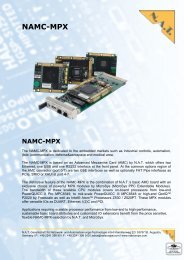
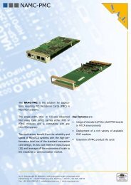
Figure 1 shows a detailed block diagram of the <strong>N<strong>AMC</strong></strong>-<strong>STM1</strong>/4.<br />
A<br />
B<br />
Rings A & B 155/622<br />
MBit<br />
Fiber<br />
Optic<br />
Fiber<br />
Optic<br />
<strong>N<strong>AMC</strong></strong>-<strong>STM1</strong>/4<br />
Figure 1: <strong>N<strong>AMC</strong></strong>-<strong>STM1</strong>/4 Block Diagram<br />
OC3/12<br />
Phy<br />
Arrow 155<br />
/Arrow 622<br />
OC3/12<br />
Phy<br />
Arrow 155<br />
/Arrow 622<br />
<strong>Telecom</strong><br />
Bus<br />
Timing<br />
<strong>Reference</strong><br />
Temux84-A<br />
63 x E1 /<br />
84 x T1<br />
Mapper /<br />
MUX<br />
Temux84-B<br />
63 x E1 /<br />
84 x T1<br />
Mapper /<br />
MUX<br />
local Bus<br />
Temux84-C<br />
63 x E1 /<br />
84 x T1<br />
Mapper /<br />
MUX<br />
Temux84-D<br />
63 x E1 /<br />
84 x T1<br />
Mapper /<br />
MUX<br />
Stratum 3<br />
PLL<br />
ZL30410<br />
SBI<br />
<strong>Reference</strong><br />
Clock<br />
iTDM/H.110<br />
TSI<br />
-<br />
Lattice SCM<br />
FPGA<br />
-<br />
Clock & Time<br />
Mangement<br />
Version 1.2 © N.A.T. GmbH 9<br />
Master<br />
Clock<br />
TDM<br />
bus<br />
PCIe<br />
GbE<br />
(iTDM)
<strong>N<strong>AMC</strong></strong>-<strong>STM1</strong>/4 – <strong>Technical</strong> <strong>Reference</strong> Manual<br />
1.1 Board Features<br />
1.1.1 FPGA<br />
The central component on the <strong>N<strong>AMC</strong></strong>-<strong>STM1</strong>/4 is a Lattice SCM FPGA (SCM40 or<br />
SCM80). This device features built-in SerDes units used to realize the physical layer of<br />
the PCIe and the GbE interfaces, as well as a structured ASIC region used to implement<br />
the higher layers of the PCIe interface.<br />
The logic resources are used to realize the iTDM engine along with the management<br />
interface and further functionality related to the SDH chipset.<br />
1.1.2 SDH Interfaces<br />
The <strong>STM1</strong>/4 / OC3/12 interface consists of the Fiber Optic interface and the Sonet/SDH<br />
framer. The PMC-Sierra device Arrow-155 is used as Sonet/SDH framer for the <strong>STM1</strong><br />
option, the Arrow-622 as framer for the STM4 option.<br />
The Arrow-155 is a single port Sonet/SDH framer supporting the OC-3 (STM-1) data<br />
rates. The Arrow-155 terminates section, line and path overhead of both the STS-n<br />
(AU-4) level and the TU-3 level. On the line side it incorporates a SERDES, allowing it<br />
to mate directly to an optics module. The system side interface is an 8-bit multi-drop<br />
parallel <strong>Telecom</strong> bus, allowing multiple devices to share a single bus. The Arrow-155<br />
maps/demaps up to three channels of DS3, E3, or EC-1 with bi-directional monitoring<br />
of traffic. The traffic may be multiplexed either into the system side or line side<br />
interfaces.<br />
For the STM4 option, the board is equipped with an Arrow-622 device.<br />
1.1.3 Backplane Interfaces<br />
PCIe: The <strong>N<strong>AMC</strong></strong>-<strong>STM1</strong>/4 includes a x1-PCI Express interface. This is<br />
implemented in the Lattice FPGA. The PCI Express interface connects to<br />
Port 4/8 of the Fat Pipe Region of the <strong>AMC</strong> backplane connector (can be<br />
switched over to support redundant system setups). The implementation<br />
of PCIe conforms to the <strong>AMC</strong>.1 specification.<br />
GbE: The <strong>N<strong>AMC</strong></strong>-<strong>STM1</strong>/4 implements a serial Type P Control Path, the<br />
physical layer of which is 1000BaseX. The Type P Control Path connects<br />
to Port 0/1 of the Common Options Region of the <strong>AMC</strong> backplane<br />
connector (can be switched over to support redundant system setups).<br />
The Control Path is connected to the iTDM FPGA, and shares the port<br />
with iTDM.<br />
iTDM: The <strong>N<strong>AMC</strong></strong>-<strong>STM1</strong>/4 implements a serial iTDM backplane interface, the<br />
physical layer of which is 1000BaseX. The iTDM interface connects to<br />
Port 0/1 of the Common Options Region of the <strong>AMC</strong> backplane<br />
connector, and shares the port with the Type P Control Path. The iTDM<br />
Version 1.2 © N.A.T. GmbH 10
<strong>N<strong>AMC</strong></strong>-<strong>STM1</strong>/4 – <strong>Technical</strong> <strong>Reference</strong> Manual<br />
interface is implemented in FPGA logic and conforms to the SFP.0 and<br />
SFP.1 specifications.<br />
IPMB: The <strong>N<strong>AMC</strong></strong>-<strong>STM1</strong>/4 implements an IPMB interface which conforms to<br />
the <strong>AMC</strong>.0 specification.<br />
TDM: The <strong>N<strong>AMC</strong></strong>-<strong>STM1</strong>/4 implements an 8 bit TDM interface, similar to<br />
H.110. The same throughput as with a complete H.110 bus is achieved by<br />
clocking the 8 backplane TDM lines with 32,768 MHz. Thus, every<br />
frame consists of 512 timeslots per line. The purpose of this TDM<br />
backplane bus is to establish ‘private’ TDM links to adjacent modules.<br />
The TDM interface is implemented in FPGA logic. The TDM interface<br />
connects to ports 12, 13 (data), and port 14 (Sync) of the Common<br />
Options Region of the <strong>AMC</strong> connector.<br />
Version 1.2 © N.A.T. GmbH 11
<strong>N<strong>AMC</strong></strong>-<strong>STM1</strong>/4 – <strong>Technical</strong> <strong>Reference</strong> Manual<br />
1.2 Board Specification<br />
Table 2: <strong>N<strong>AMC</strong></strong>-<strong>STM1</strong>/4 Features<br />
<strong>AMC</strong>-<strong>Module</strong> standard Advanced Mezzanine Card, single width, double height<br />
Front-I/O Two optical 155/622Mbps OC-3/12 STM-1 line interfaces<br />
Power consumption 12V 1.3A max.<br />
Environmental<br />
conditions<br />
Temperature (operating):<br />
Temperature (storage):<br />
Humidity:<br />
Standards compliance PICMG <strong>AMC</strong>.0 Rev. 2.0<br />
PICMG <strong>AMC</strong>.1 Rev. 1.0<br />
0°C to +50°C with forced cooling<br />
-40°C to +85°C<br />
PCI Express Base Specification Rev. 1.1<br />
10 % to 90 % rh noncondensing<br />
PICMG SFP.0 Rev. 1.0 (System Fabric Plane Format)<br />
PICMG SFP.1 Rev. 1.0 (Internal TDM)<br />
IPMI Specification v2.0 Rev. 1.0<br />
PICMG µTCA.0 Rev. 1.0<br />
Version 1.2 © N.A.T. GmbH 12
<strong>N<strong>AMC</strong></strong>-<strong>STM1</strong>/4 – <strong>Technical</strong> <strong>Reference</strong> Manual<br />
2 Installation<br />
2.1 Safety Note<br />
CAUTION<br />
To ensure proper functioning of the <strong>N<strong>AMC</strong></strong>-<strong>STM1</strong>/4 during its usual lifetime<br />
take the following precautions before handling the board.<br />
Electrostatic discharge and incorrect board installation and uninstallation can<br />
damage circuits or shorten their lifetime.<br />
• Before installing or uninstalling the <strong>N<strong>AMC</strong></strong>-<strong>STM1</strong>/4 read this installation<br />
section<br />
• Before installing or uninstalling the <strong>N<strong>AMC</strong></strong>-<strong>STM1</strong>/4, read the Installation<br />
Guide and the User’s Manual of the carrier board used, or of the uTCA<br />
system the board will be plugged into.<br />
• Before installing or uninstalling the <strong>N<strong>AMC</strong></strong>-<strong>STM1</strong>/4 on a carrier board or<br />
both in a rack:<br />
- Check all installed boards and modules for steps that you have to take<br />
before turning on or off the power.<br />
- Take those steps.<br />
- Finally turn on or off the power if necessary.<br />
- Make sure the part to be installed / removed is hot swap capable, if you<br />
don’t switch off the power.<br />
• Before touching integrated circuits ensure to take all require precautions for<br />
handling electrostatic devices.<br />
• Ensure that the <strong>N<strong>AMC</strong></strong>-<strong>STM1</strong>/4 is connected to the carrier board or to the<br />
uTCA backplane with the connector completely inserted.<br />
• When operating the board in areas of strong electromagnetic radiation<br />
ensure that the module<br />
- is bolted the front panel or rack<br />
- and shielded by closed housing<br />
Version 1.2 © N.A.T. GmbH 13
<strong>N<strong>AMC</strong></strong>-<strong>STM1</strong>/4 – <strong>Technical</strong> <strong>Reference</strong> Manual<br />
2.2 Installation Prerequisites and Requirements<br />
IMPORTANT<br />
Before powering up<br />
• check this section for installation prerequisites and requirements<br />
2.2.1 Requirements<br />
2.2.2 Power supply<br />
The installation requires only<br />
• an ATCA carrier board, or a µTCA backplane for connecting the <strong>N<strong>AMC</strong></strong>-<br />
<strong>STM1</strong>/4<br />
• power supply<br />
• cooling devices<br />
The power supply for the <strong>N<strong>AMC</strong></strong>-<strong>STM1</strong>/4 must meet the following specifications:<br />
• required for the module:<br />
+12V / 1.3A max.<br />
+ 3,3V / 0.15A max.<br />
2.2.3 Automatic Power Up<br />
In the following situations the <strong>N<strong>AMC</strong></strong>-<strong>STM1</strong>/4 will automatically be reset and proceed<br />
with a normal power up.<br />
Voltage sensors<br />
The voltage sensor generates a reset<br />
• when +12V voltage level drops below 8V<br />
• when +3.3V voltage level drops below 3.08V<br />
or when the carrier board / backplane signals a PCIe Reset.<br />
Version 1.2 © N.A.T. GmbH 14
<strong>N<strong>AMC</strong></strong>-<strong>STM1</strong>/4 – <strong>Technical</strong> <strong>Reference</strong> Manual<br />
2.3 Statement on Environmental Protection<br />
2.3.1 Compliance to RoHS Directive<br />
Directive 2002/95/EC of the European Commission on the "Restriction of the use of<br />
certain Hazardous Substances in Electrical and Electronic Equipment" (RoHS)<br />
predicts that all electrical and electronic equipment being put on the European market<br />
after June 30th, 2006 must contain lead, mercury, hexavalent chromium,<br />
polybrominated biphenyls (PBB) and polybrominated diphenyl ethers (PBDE) and<br />
cadmium in maximum concentration values of 0.1% respective 0.01% by weight in<br />
homogenous materials only.<br />
As these hazardous substances are currently used with semiconductors, plastics (i.e.<br />
semiconductor packages, connectors) and soldering tin any hardware product is<br />
affected by the RoHS directive if it does not belong to one of the groups of products<br />
exempted from the RoHS directive.<br />
Although many of hardware products of N.A.T. are exempted from the RoHS<br />
directive it is a declared policy of N.A.T. to provide all products fully compliant to the<br />
RoHS directive as soon as possible. For this purpose since January 31st, 2005 N.A.T.<br />
is requesting RoHS compliant deliveries from its suppliers. Special attention and care<br />
has been paid to the production cycle, so that wherever and whenever possible RoHS<br />
components are used with N.A.T. hardware products already.<br />
2.3.2 Compliance to WEEE Directive<br />
Directive 2002/95/EC of the European Commission on "Waste Electrical and<br />
Electronic Equipment" (WEEE) predicts that every manufacturer of electrical and<br />
electronical equipment which is put on the European market has to contribute to the<br />
reuse, recycling and other forms of recovery of such waste so as to reduce disposal.<br />
Moreover this directive refers to the Directive 2002/95/EC of the European<br />
Commission on the "Restriction of the use of certain Hazardous Substances in<br />
Electrical and Electronic Equipment" (RoHS).<br />
Having its main focus on private persons and households using such electrical and<br />
electronic equipment the directive also affects business-to-business relationships. The<br />
directive is quite restrictive on how such waste of private persons and households has<br />
to be handled by the supplier/manufacturer; however, it allows a greater flexibility in<br />
business-to-business relationships. This pays tribute to the fact with industrial use<br />
electrical and electronical products are commonly integrated into larger and more<br />
complex environments or systems that cannot easily be split up again when it comes to<br />
their disposal at the end of their life cycles.<br />
Version 1.2 © N.A.T. GmbH 15
<strong>N<strong>AMC</strong></strong>-<strong>STM1</strong>/4 – <strong>Technical</strong> <strong>Reference</strong> Manual<br />
As N.A.T. products are solely sold to industrial customers, by special arrangement at<br />
time of purchase the customer agreed to take the responsibility for a WEEE compliant<br />
disposal of the used N.A.T. product. Moreover, all N.A.T. products are marked<br />
according to the directive with a crossed out bin to indicate that these products within<br />
the European Community must not be disposed with regular waste.<br />
If you have any questions on the policy of N.A.T. regarding the Directive 2002/95/EC<br />
of the European Commission on the "Restriction of the use of certain Hazardous<br />
Substances in Electrical and Electronic Equipment" (RoHS) or the Directive<br />
2002/95/EC of the European Commission on "Waste Electrical and Electronic<br />
Equipment" (WEEE) please contact N.A.T. by phone or e-mail.<br />
2.3.3 Compliance to CE Directive<br />
Compliance to the CE directive is declared. A ‘CE’ sign can be found on the PCB.<br />
2.3.4 Product Safety<br />
The board complies with EN60950 and UL1950.<br />
Version 1.2 © N.A.T. GmbH 16
<strong>N<strong>AMC</strong></strong>-<strong>STM1</strong>/4 – <strong>Technical</strong> <strong>Reference</strong> Manual<br />
3 Functional Blocks<br />
The <strong>N<strong>AMC</strong></strong>-<strong>STM1</strong>/4 can be divided into a number of functional blocks, which are described<br />
in the following paragraphs.<br />
3.1.1 FPGA<br />
The FPGA implements the following functional blocks:<br />
• Logic to interface the SBI bus; clock management for the SDH chipset<br />
• iTDM controller with GbE.<br />
• PCIe interface for management<br />
• Management over GbE<br />
• Legacy TSI between SBI timeslots and backplane TDM bus<br />
3.1.2 PCI Express Interface<br />
The <strong>N<strong>AMC</strong></strong>-<strong>STM1</strong>/4 includes a 1 lane PCI Express interface. This is implemented in the<br />
Lattice SCM FPGA. The PCIe interface may receive its reference clock either from the Clock<br />
3 port of the <strong>AMC</strong> backplane connector, or from a local 100 MHz oscillator circuitry<br />
(default). The clock source is programmable.<br />
3.1.3 Backplane Ethernet<br />
The backplane Ethernet interface implemented within the FPGA can be switched to operate<br />
on <strong>AMC</strong> Port 0 or Port 1 for redundant operation. Within FPGA logic the Type P Control<br />
Path data is multiplexed with the iTDM data and transferred through the same physical port.<br />
By default, the LIU is programmed to connect to Port 0 of the Common Options Region of<br />
the <strong>AMC</strong> backplane connector. It can also be programmed to connect to Port 1, in order to<br />
support a redundant µTCA system.<br />
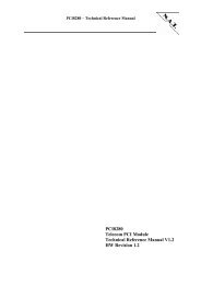
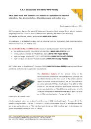
3.1.4 iTDM<br />
The iTDM controller within the FPGA can be used to transfer any of the SDH timeslots via<br />
GbE packets. It supports mixed operation in either 125µs mode or 1ms mode. The capacity is<br />
limited to 8192 timeslots, due to the available bandwidth of the GbE link.<br />
16<br />
16<br />
16<br />
to<br />
Control<br />
Path<br />
Tx-Control-<br />
Memory<br />
Register Set<br />
Rx-Control-<br />
Memory<br />
Figure 2: Organisation of the iTDM FPGA<br />
16<br />
16<br />
16<br />
16<br />
Tx State<br />
Machine<br />
Rx State<br />
Machine<br />
Clocking<br />
8<br />
Ethernet Tx<br />
Memory<br />
8 8<br />
8<br />
FIFO<br />
FIFO<br />
TDM Block<br />
Ethernet Rx<br />
Memory<br />
8 8<br />
GbE<br />
Block<br />
Version 1.2 © N.A.T. GmbH 17
<strong>N<strong>AMC</strong></strong>-<strong>STM1</strong>/4 – <strong>Technical</strong> <strong>Reference</strong> Manual<br />
3.1.5 Backplane TDM<br />
The <strong>N<strong>AMC</strong></strong>-<strong>STM1</strong>/4 implements an 8 bit TDM interface, similar to H.110. The same<br />
throughput as with a complete H.110 bus is achieved by clocking the 8 backplane TDM lines<br />
with 32,768 MHz. Thus, every frame consists of 512 timeslots per line. The purpose of this<br />
TDM backplane bus is to establish ‘private’ TDM links to adjacent modules. The TDM<br />
interface is implemented in FPGA logic. The TDM interface connects to ports 12, 13 (data),<br />
and port 14 (Sync) of the Extended Options Region of the <strong>AMC</strong> connector.<br />
3.2 SDH Line Interfaces<br />
The two optical 155/622Mbps OC-3/12 STM-1 line interfaces are available on two standard<br />
OC-3/12 SDH/STM-1 SC-connectors at the front panel.<br />
3.3 <strong>AMC</strong> Clock Interface<br />
The <strong>N<strong>AMC</strong></strong>-<strong>STM1</strong>/4 implements a very flexible clocking functionality concerning the <strong>AMC</strong><br />
backplane clock ports Clock 1 – Clock 3.<br />
<strong>AMC</strong> backplane clock port Clock 1 is connected to the FPGA, in order to be used as a<br />
<strong>Telecom</strong> standard clock. Clock 1 is only received.<br />
<strong>AMC</strong> backplane clock port Clock 2 is connected to the FPGA, in order to be used as a<br />
<strong>Telecom</strong> standard reference. Clock 2 may be received from or transmitted to the backplane, in<br />
order to become the reference clock for the entire system.<br />
<strong>AMC</strong> backplane clock port Clock 3 is connected to the PCIe interface, in order to be used as a<br />
reference clock for PCI Express. Clock 3 is only received. Clock 3 is routed to a multiplexer,<br />
which allows programming the clock source of the PCIe line to be either Clock 3, or an<br />
internal differential 100 MHz reference clock.<br />
In case clock 3 is to be used for a different functionality, it also feeds the FPGA and may be<br />
used there for any suitable purpose.<br />
Version 1.2 © N.A.T. GmbH 18
<strong>N<strong>AMC</strong></strong>-<strong>STM1</strong>/4 – <strong>Technical</strong> <strong>Reference</strong> Manual<br />
3.4 IPMB Interface<br />
The <strong>N<strong>AMC</strong></strong>-<strong>STM1</strong>/4 implements an IPMB interface consisting of an ATMega168<br />
microcontroller and a couple of I2C devices, such as a temperature sensor, and an EEPROM.<br />
The IPMB controller manages also the hot swap functionality and the geographical address as<br />
requested by the <strong>AMC</strong> specification.<br />
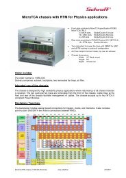
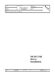
3.4.1 I 2 C Devices<br />
Three I 2 C busses connect to the IPMI controller. The first one is the IPMB bus of the <strong>AMC</strong><br />
connector, and the two other interface various local devices. The local devices, all powered by<br />
IPMB power, are an EEPROM (24C08) for storage of board-specific information, and a<br />
temperature sensor, which is capable of reading the FPGA’s die temperature. The third local<br />
I²C device is the hotswap controller of the <strong>N<strong>AMC</strong></strong>-<strong>STM1</strong>/4.<br />
Figure 3: I²C Structure of the <strong>N<strong>AMC</strong></strong>-<strong>STM1</strong>/4<br />
HotSwap<br />
Controller<br />
EEPROM<br />
24C08<br />
Temp.Sens.<br />
Max6642<br />
<strong>N<strong>AMC</strong></strong>-<strong>STM1</strong>/4<br />
local<br />
i2c bus 2<br />
local<br />
i2c bus 1<br />
Atmel<br />
ATMega168<br />
µC<br />
IPMB-L<br />
Version 1.2 © N.A.T. GmbH 19
<strong>N<strong>AMC</strong></strong>-<strong>STM1</strong>/4 – <strong>Technical</strong> <strong>Reference</strong> Manual<br />
4 Hardware<br />
4.1 <strong>AMC</strong> Port Definition<br />
Basic Connector<br />
Extended Connector<br />
Table 3: <strong>AMC</strong> Port Definition<br />
Port <strong>AMC</strong> Port Mapping Ports used as<br />
No. Strategy<br />
CLK1 <strong>Reference</strong> Clock 1<br />
CLK2 Clocks<br />
<strong>Reference</strong> Clock 2<br />
CLK3<br />
<strong>Reference</strong> Clock 3<br />
0 Common 1000BaseX Ethernet Channel 1<br />
Options<br />
(iTDM and Type P), default<br />
1 Region<br />
1000BaseX Ethernet Channel 2<br />
(iTDM and Type P), redundant<br />
2 unassigned<br />
3<br />
unassigned<br />
4 PCI Express Lane 0, default<br />
5 unassigned<br />
6 Fat<br />
unassigned<br />
7<br />
Pipes unassigned<br />
8 Region<br />
PCI Express Lane 0, redundant<br />
9 unassigned<br />
10 unassigned<br />
11<br />
unassigned<br />
12 TDM Bus D0-3 (H.110 extended)<br />
13 TDM Bus D4-7 (H.110 extended)<br />
14 optional clock lines (H.110 extended)/<br />
Extended unassigned<br />
15 Options<br />
Unassigned<br />
CLK4/5 Region<br />
Unassigned<br />
17 Unassigned<br />
18 Unassigned<br />
19 Unassigned<br />
20<br />
Unassigned<br />
Version 1.2 © N.A.T. GmbH 20
<strong>N<strong>AMC</strong></strong>-<strong>STM1</strong>/4 – <strong>Technical</strong> <strong>Reference</strong> Manual<br />
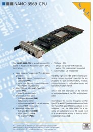
4.2 Front Panel and LEDs<br />
The <strong>N<strong>AMC</strong></strong>-<strong>STM1</strong>/4 module is equipped with 4 LEDs, which are software programmable.<br />
They are mounted between the SDH connectors.<br />
Additionally it features the standard four <strong>AMC</strong> LEDs, with the red and blue LED being<br />
controlled by the IPMB-µC, and the green and yellow one being controlled via FPGA<br />
registers.<br />
LED<br />
Port<br />
A<br />
Figure 4: Front Panel<br />
4xgreen<br />
4<br />
2<br />
1<br />
Port<br />
B<br />
Table 4: LED Functionality<br />
3<br />
Function<br />
1 no default functionality; can be controlled by software<br />
2 no default functionality; can be controlled by software<br />
3 no default functionality; can be controlled by software<br />
4 no default functionality; can be controlled by software<br />
blue <strong>AMC</strong> Hotswap LED<br />
red <strong>AMC</strong> Error LED<br />
green default: Lock Status PLL; can be overridden by software<br />
yellow default: Activity Ethernet; can be overridden by software<br />
Version 1.2 © N.A.T. GmbH 21<br />
yellow<br />
green<br />
red<br />
blue
<strong>N<strong>AMC</strong></strong>-<strong>STM1</strong>/4 – <strong>Technical</strong> <strong>Reference</strong> Manual<br />
5 Connectors<br />
5.1 Connector Overview<br />
J<br />
1<br />
Figure 5: Connectors of the <strong>N<strong>AMC</strong></strong>-<strong>STM1</strong>/4<br />
SW1<br />
JP2<br />
1<br />
1<br />
JP1<br />
Please refer to the following tables to look up the connector pin assignment of the <strong>N<strong>AMC</strong></strong>-<br />
<strong>STM1</strong>/4.<br />
Version 1.2 © N.A.T. GmbH 22<br />
JP3<br />
1<br />
<strong>AMC</strong><br />
LEDs<br />
S1<br />
GP<br />
LEDs<br />
S2
<strong>N<strong>AMC</strong></strong>-<strong>STM1</strong>/4 – <strong>Technical</strong> <strong>Reference</strong> Manual<br />
5.2 <strong>AMC</strong> Connector J1<br />
Pin No.<br />
Table 5: <strong>AMC</strong> Connector J1<br />
<strong>AMC</strong>-Signal <strong>AMC</strong>-Signal Pin No.<br />
1 GND GND 170<br />
2 PWR TDI 169<br />
3 /PS1 TDO 168<br />
4 PWR_IPMB /TRST 167<br />
5 GA0 TMS 166<br />
6 RESVD TCK 165<br />
7 GND GND 164<br />
8 RESVD /SPISEL 163<br />
9 PWR SPICLK 162<br />
10 GND GND 161<br />
11 XLINK1_P SPIMOSI 160<br />
12 XLINK1_N SPIMISO 159<br />
13 GND GND 158<br />
14 RLINK1_P PORT19TX_P 157<br />
15 RLINK1_N PORT19TX_N 156<br />
16 GND GND 155<br />
17 GA1 PORT19RX_P 154<br />
18 PWR PORT19RX_N 153<br />
19 GND GND 152<br />
20 XLINK2_P PORT18TX_P 151<br />
21 XLINK2_N PORT18TX_N 150<br />
22 GND GND 149<br />
23 RLINK2_P PORT18RX_P 148<br />
24 RLINK2_N PORT18RX_N 147<br />
25 GND GND 146<br />
26 GA2 NC 145<br />
27 PWR NC 144<br />
28 GND GND 143<br />
29 NC NC 142<br />
30 NC NC 141<br />
31 GND GND 140<br />
32 NC NC 139<br />
33 NC NC 138<br />
34 GND GND 137<br />
35 NC NC 136<br />
36 NC NC 135<br />
37 GND GND 134<br />
Version 1.2 © N.A.T. GmbH 23
<strong>N<strong>AMC</strong></strong>-<strong>STM1</strong>/4 – <strong>Technical</strong> <strong>Reference</strong> Manual<br />
Pin No.<br />
<strong>AMC</strong>-Signal <strong>AMC</strong>-Signal Pin No.<br />
38 NC NC 133<br />
39 NC NC 132<br />
40 GND GND 131<br />
41 /ENABLE NC 130<br />
42 PWR NC 129<br />
43 GND GND 128<br />
44 PET0_P_P4 RESVD 127<br />
45 PET0_N_P4 TDM_REF 126<br />
46 GND GND 125<br />
47 PER0_P_P4 TDM_FS 124<br />
48 PER0_N_P4 TDM_CLK 123<br />
49 GND GND 122<br />
50 NC TDM7 121<br />
51 NC TDM6 120<br />
52 GND GND 119<br />
53 PER1_P TDM5 118<br />
54 PER1_N TDM4 117<br />
55 GND GND 116<br />
56 IPMB_SCL TDM3 115<br />
57 PWR TDM2 114<br />
58 GND GND 113<br />
59 NC TDM1 112<br />
60 NC TDM0 111<br />
61 GND GND 110<br />
62 NC NC 109<br />
63 NC NC 108<br />
64 GND GND 107<br />
65 NC NC 106<br />
66 NC NC 105<br />
67 GND GND 104<br />
68 NC NC 103<br />
69 NC NC 102<br />
70 GND GND 101<br />
71 IPMB_SDA NC 100<br />
72 PWR NC 99<br />
73 GND GND 98<br />
74 CLK_1_P NC 97<br />
75 CLK_1_N NC 96<br />
76 GND GND 95<br />
77 CLK_2_P NC 94<br />
78 CLK_2_N NC 93<br />
Version 1.2 © N.A.T. GmbH 24
<strong>N<strong>AMC</strong></strong>-<strong>STM1</strong>/4 – <strong>Technical</strong> <strong>Reference</strong> Manual<br />
Pin No.<br />
<strong>AMC</strong>-Signal <strong>AMC</strong>-Signal Pin No.<br />
79 GND GND 92<br />
80 CLK_3_P PET0_P_P8 91<br />
81 CLK_3_N PET0_N_P8 90<br />
82 GND GND 89<br />
83 /PS0 PER0_P_P8 88<br />
84 PWR PER0_N_P8 87<br />
85 GND GND 86<br />
5.3 Connector JP1: IPMI-µC Programming Port<br />
Connector JP2 connects the programming-port of the Atmel AVR µC device.<br />
Table 6: Atmel AVR Programming Port<br />
Pin No.<br />
Signal<br />
1 MISO<br />
2 VCC_IPMB<br />
3 SCK<br />
4 MOSI<br />
5 /RST_IMPI<br />
6 GND<br />
5.4 Connector JP2: Lattice FPGA programming port<br />
Connector JP2 connects the JTAG- or programming-port of the Lattice FPGA device.<br />
Table 7: Lattice programming port<br />
Pin No.<br />
Signal Signal Pin No.<br />
1 +3.3V TDO 2<br />
3 TDI /PROGRAM 4<br />
5 nc TMS 6<br />
7 GND TCK 8<br />
9 DONE_LAT /INIT_LAT 10<br />
Version 1.2 © N.A.T. GmbH 25
<strong>N<strong>AMC</strong></strong>-<strong>STM1</strong>/4 – <strong>Technical</strong> <strong>Reference</strong> Manual<br />
5.5 Connector JP3: JTAG connector<br />
This JTAG port connects to the JTAG interfaces of the Arrow and Temux devices, which are<br />
configured in a daisy chain.<br />
Pin No.<br />
5.6 Hot Swap Switch SW1<br />
Table 8: JTAG Connector Pinout<br />
Signal Signal Pin No.<br />
1 TCK GND 2<br />
3 TDO +3,3V 4<br />
5 TMS nc 6<br />
7 nc nc 8<br />
9 TDI GND 10<br />
Switch SW1 is used to support hot swapping of the module. It conforms to PICMG <strong>AMC</strong>.0.<br />
5.7 The Front Panel Connectors (S1 – S2)<br />
The two optical front panel connectors have standard SC-plugs, and can be equipped with<br />
either singlemode or multimode transceivers.<br />
Version 1.2 © N.A.T. GmbH 26
<strong>N<strong>AMC</strong></strong>-<strong>STM1</strong>/4 – <strong>Technical</strong> <strong>Reference</strong> Manual<br />
6 <strong>N<strong>AMC</strong></strong>-<strong>STM1</strong>/4 Programming Notes<br />
The FPGA on the <strong>N<strong>AMC</strong></strong>-<strong>STM1</strong>/4 realizes the interface to the onboard devices and an<br />
iTDM-to-TDM conversion engine. The table below shows the memory map for the logical<br />
sub-blocks of the design. Refer to the following sub-chapters for detailed information.<br />
All devices shown in this memory map can be accessed either via PCIe or via the so called<br />
Ethernet Control Interface. This Interface uses a N.A.T. proprietary protocol based on Layer2<br />
Ethernet frames to perform memory mapped accesses via Ethernet. Please refer to the<br />
Ethernet Control Interface <strong>Technical</strong> <strong>Reference</strong> Manual for further information [9].<br />
The MAC address of the <strong>N<strong>AMC</strong></strong>-<strong>STM1</strong>/4 is build with the following scheme:<br />
00:40:42:14:XX:XX with XXXX being the boards serial number in hexadecimal<br />
representation<br />
Table 9: FPGA Memory Map<br />
Address Offset Logical Block<br />
0x00000 General Purpose Status (read-only)<br />
0x00100 General Purpose Registers<br />
0x01000 Interface to SPI FPGA PROM<br />
0x08000 Arrow Framer 0<br />
0x0c000 Arrow Framer 1<br />
0x10000 Temux 0<br />
0x14000 Temux 2<br />
0x18000 Temux 1<br />
0x1c000 Temux 3<br />
0x20000 GbE-Interface Block<br />
0x80000 iTDM Block<br />
The FPGA-Design consists of four main blocks:<br />
• Misc. board control- and status registers, and a register-interface to access the FPGA’s<br />
PROM<br />
• Ethernet Control Interface<br />
• Interface to Arrow and Temux Devices<br />
• GbE-MAC and frame preprocessing block<br />
• iTDM block<br />
Version 1.2 © N.A.T. GmbH 27
<strong>N<strong>AMC</strong></strong>-<strong>STM1</strong>/4 – <strong>Technical</strong> <strong>Reference</strong> Manual<br />
6.1.1 FPGA GP Registers/Status<br />
This chapter describes the basic board control registers implemented within the FPGA.<br />
Further register description will follow up in future versions of this manual.<br />
6.1.1.1 PCB Version Register<br />
The Version Register holds the PCB Revision, encoded in two nibbles.<br />
Table 10: PCB Version Register<br />
PCB Version - Address 0x00<br />
Default value 0x0011<br />
Bit 15..8 7..4 3..0<br />
Access R R R<br />
Func reserved Version Major Version Minor<br />
6.1.1.2 FPGA Version Register<br />
The Version Register holds the FPGA Revision, encoded in two nibbles.<br />
Table 11: FPGA Version Register<br />
FPGA Version - Address 0x02<br />
Default value 0x0015<br />
Bit 15..8 7..4 3..0<br />
Access R R R<br />
Func reserved Version Major Version Minor<br />
6.1.1.3 FPGA ID_1 Register<br />
This read only register can be used by the device driver to probe register access.<br />
Table 12: FPGA ID_1 Register<br />
FPGA ID_1 - Address 0x04<br />
Default value 0xAA55<br />
Bit 15..0<br />
Access R<br />
Func ID_1<br />
6.1.1.4 FPGA ID_2 Register<br />
This read only register can be used by the device driver to probe register access.<br />
Table 13: FPGA ID_2 Register<br />
FPGA ID_2 - Address 0x06<br />
Default value 0xDEAD<br />
Bit 15..0<br />
Access R<br />
Func ID_2<br />
Version 1.2 © N.A.T. GmbH 28
<strong>N<strong>AMC</strong></strong>-<strong>STM1</strong>/4 – <strong>Technical</strong> <strong>Reference</strong> Manual<br />
6.1.1.5 FPGA BOARD_ID Register<br />
This read only register can be used by the device driver to probe register access. It holds the<br />
N.A.T. internal board-id of the <strong>N<strong>AMC</strong></strong>-<strong>STM1</strong>/4.<br />
Table 14: FPGA BOARD_ID Register<br />
FPGA BOARD_ID - Address 0x08<br />
Default value 0x0B06<br />
Bit 15..0<br />
Access R<br />
Func BOARD_ID<br />
6.1.1.6 PLL Status Register<br />
The bits within this register show the logical value of the Zarlink ZL304010 PLL status<br />
outputs. Please refer to the ZL304010 manual for detailed information.<br />
Table 15: PLL Status Register<br />
PLL Status – Address Offset 0x0A<br />
Default value 0x0000<br />
Bit 15..4 3 2 1 0<br />
Access R R R R R<br />
Func reserved SECOR PRIOR HLDOV LOCK<br />
6.1.1.7 IRQ Status Register<br />
This register displays the interrupt status line of all interrupt capable devices on the <strong>N<strong>AMC</strong></strong>-<br />
<strong>STM1</strong>/4. A value of ‘1’ means that the respective interrupt is pending. An IRQ transmitted<br />
via ECI (Ethernet Control Interface) is acknowledged and re-armed by writing a ‘1’ to the<br />
corresponding bit.<br />
Table 16: IRQ Status Register<br />
IRQ Status - Address 0x0C<br />
Default value 0x0000<br />
Bit 15..8 7 6 5 4 3 2 1 0<br />
Access R R R R R R R R R<br />
Func reserved ZPLL iTDM Temux 3 Temux 2 Temux 1 Temux 0 Arrow 1 Arrow 0<br />
6.1.1.8 IRQ Enable Register<br />
This register holds the bits to enable the interrupts being present in the IRQ Status Register.<br />
Table 17: IRQ Enable Register<br />
IRQ Enable - Address 0x10C<br />
Default value 0x0000<br />
Bit 15..8 7 6 5 4 3 2 1 0<br />
Access R/W R/W R/W R/W R/W R/W R/W R/W R/W<br />
Func reserved ZPLL iTDM Temux 3 Temux 2 Temux 1 Temux 0 Arrow 1 Arrow 0<br />
Version 1.2 © N.A.T. GmbH 29
<strong>N<strong>AMC</strong></strong>-<strong>STM1</strong>/4 – <strong>Technical</strong> <strong>Reference</strong> Manual<br />
6.1.1.9 FPGA Reset Register<br />
The Reset Register is used to trigger a reset to the whole FPGA logic, FPGA blocks, or<br />
external devices. Writing a ‘1’ to a bit triggers the reset. After reset, the bit is self-cleared to<br />
‘0’.<br />
Table 18: FPGA Reset Register<br />
Reset – Address Offset 0x100<br />
Default value 0x0000<br />
Bit 15 6 5 4 3 2 1 0<br />
Access R/W R/W R/W R/W R/W R/W R/W R/W<br />
Func<br />
Board<br />
global<br />
IPMI-µC Eth-Cntr-Int. SPI-Interf. SBI-bus GbE iTDM<br />
Arrow<br />
Temux<br />
6.1.1.10 GP LEDs Register<br />
This register is used to control the four general purpose LEDs on the <strong>AMC</strong> module front<br />
panel between the optical connectors. The GP LEDs can be configured to the functionality<br />
listed below:<br />
Table 19: GP LEDs Register<br />
GP LEDs - Address 0x102<br />
Default value 0x0000<br />
Bit 15..12 11..8 7..4 3..0<br />
Access R/W R/W R/W R/W<br />
Func GP LED 4 GP LED 3 GP LED 2 GP LED 1<br />
Table 20: GP LEDs Values<br />
Value<br />
0x0 off<br />
0x1 on<br />
0x2 slow blink<br />
0x3 fast blink<br />
others reserved<br />
GP-LED Functions<br />
6.1.1.11 <strong>AMC</strong> LEDs Register<br />
This register is used to control the <strong>AMC</strong> LEDs 3 (most upper; yellow) and 2 (second from<br />
top; green) on the <strong>AMC</strong> module front panel.<br />
Note: the other two <strong>AMC</strong> LEDs (LED 1 and LED blue) are controlled by the IPMI-µC.<br />
Table 21: <strong>AMC</strong> LEDs Register<br />
<strong>AMC</strong> LEDs - Address 0x104<br />
Default value 0x0054<br />
Bit 15..8 7..4 3..0<br />
Access R/W R/W R/W<br />
Func reserved LED <strong>AMC</strong> 3 LED <strong>AMC</strong> 2<br />
Version 1.2 © N.A.T. GmbH 30
<strong>N<strong>AMC</strong></strong>-<strong>STM1</strong>/4 – <strong>Technical</strong> <strong>Reference</strong> Manual<br />
Table 22: <strong>AMC</strong> LED Values<br />
Value<br />
<strong>AMC</strong>-LED Functions<br />
0x0 off<br />
0x1 on<br />
0x2 slow blink<br />
0x3 fast blink<br />
0x4 TDM-PLL Lock Status<br />
0x5 Ethernet activity<br />
others reserved<br />
6.1.1.12 PLL Control Register<br />
The PLL Control Register configures the main 77.76 MHz <strong>Telecom</strong> clock configuration.<br />
The status of the PLL can be read on the PLL Status register. Please refer to the ZL304010<br />
manual for detailed information.<br />
Table 23: PLL Control Register<br />
PLL Control - Address 0x106<br />
Default value 0x0028<br />
Bit 15 14 13 12 11 10 9 8 7 6 5 4 3 2 1 0<br />
Access R/W R/W R/W R/W R/W R/W R/W R/W R/W R/W R/W R/W R/W R/W R/W R/W<br />
Func Ref1_Sel Ref0_Sel /DS3 /OC3 OE FCS Ref<br />
All<br />
Bit<br />
Table 24: PLL Control - Register Bits<br />
Name Function<br />
[15..12] Ref1_Sel Selectors for each PLL’s <strong>Reference</strong> Input:<br />
0x0 – 77,76MHz Oscillator<br />
[11..8] Ref0_Sel<br />
0x1 – Arrow_0<br />
0x2 – Arrow_1<br />
0x3 – <strong>AMC</strong>_Clk_3 / FCLK_A<br />
0x4 – <strong>AMC</strong>_Clk_1 / TCLK_A<br />
0x5 – <strong>AMC</strong>_Clk_2 / TCLK_B<br />
0x6 – TCLK_C<br />
0x7 – TCLK_D<br />
[2..1] Mode Main PLL Mode Selection<br />
0x0 – Normal Mode<br />
0x1 – Holdover Mode<br />
0x2 – Free running Mode<br />
0x3 – reserved<br />
[0] RefSel Select <strong>Reference</strong> Input of PLL (Input 0 or 1)<br />
Version 1.2 © N.A.T. GmbH 31<br />
Mode<br />
Ref<br />
Sel
<strong>N<strong>AMC</strong></strong>-<strong>STM1</strong>/4 – <strong>Technical</strong> <strong>Reference</strong> Manual<br />
6.1.1.13 Misc Clock Config Register<br />
This register holds the bits to select from which source the Arrow framer chips shall take its<br />
reference and the configuration bit for the <strong>AMC</strong> clock setup.<br />
Table 25: Misc Clock Config Register<br />
Misc Clock Config - Address 0x108<br />
Default value 0x0001<br />
Bit 15 14 13 12 11 10 9 8 7 6 5 4 3 2 1 0<br />
Access R/W R/W R/W R/W R/W R/W R/W R/W R/W R/W R/W R/W R/W R/W R/<br />
W<br />
R/W<br />
Func reserved reserved<br />
Arrow<br />
RefClock<br />
Bit<br />
[1..0] Arrow<br />
RefClock<br />
Table 26: Misc Clock Config - Register Bits<br />
Name Function<br />
Select <strong>Reference</strong> Clock for Arrow devices:<br />
0x0: Local 77,76MHz oscillator<br />
0x1: 77,76MHz from PLL<br />
6.1.1.14 SBI-bus Mode Register<br />
This register holds the configuration bits for the SBI-bus interface within the FPGA.<br />
Table 27: SBI-bus Mode Register<br />
SBI-bus Mode - Address 0x10a<br />
Default value 0x0000<br />
Bit 15 14 13 12 11 10 9 8 7 6 5 4 3 2 1 0<br />
Access R/W R/W R/W R/W R/W R/W R/W R/W R/W R/W R/W R/W R/W R/W R/W R/W<br />
Func reserved<br />
T1_E<br />
nable<br />
Bit<br />
[1] SBI_T1_Ena<br />
ble<br />
Table 28: SBI-bus Mode - Register Bits<br />
Name Function<br />
Writing this bit to ‘1’ makes the SBI-bus timeslot<br />
accessible that are used in T1 mode. A ‘0’ makes the E1<br />
timeslots accessible.<br />
Version 1.2 © N.A.T. GmbH 32
<strong>N<strong>AMC</strong></strong>-<strong>STM1</strong>/4 – <strong>Technical</strong> <strong>Reference</strong> Manual<br />
6.1.1.15 <strong>AMC</strong>-Clock Output Register<br />
Each nibble within this register controls whether one of the four telecom <strong>AMC</strong> clocks is being<br />
driven and with which source. Note the different naming schemes: TCLKA equals<br />
<strong>AMC</strong>_CLK1; TCLKB equals <strong>AMC</strong>_CLK2.<br />
Table 29: <strong>AMC</strong>-Clock Output Register<br />
ACM-Clk Output - Address 0x10e<br />
Default value 0x0000<br />
Bit 15 14 13 12 11 10 9 8 7 6 5 4 3 2 1 0<br />
Access R/W R/W R/W R/W R/W R/W R/W R/W R/W R/W R/W R/W R/W R/W R/W R/W<br />
Func TCLKD_OSEL TCLKC_OSEL<br />
Bit<br />
[15..12]<br />
[11..8]<br />
[7..4]<br />
[3..0]<br />
TCLKB_OSEL<br />
(<strong>AMC</strong>_CLK2_OSEL)<br />
Table 30: <strong>AMC</strong>-Clock Output Register Bits<br />
Name Function<br />
TCLKx_<br />
OSEL<br />
Selector for the respective clock output:<br />
0x0 – do not drive clock<br />
0x1 – drive with 8kHz<br />
0x2 – drive with 19,44MHz<br />
0x3 – drive with 2,048MHz<br />
others – drive with 8kHz<br />
TCLKA_OSEL<br />
(<strong>AMC</strong>_CLK1_OSEL)<br />
6.1.1.16 <strong>AMC</strong> Site Number<br />
This register displays the <strong>AMC</strong> Site number the module is in. This information is written into<br />
the FPGA upon power-up by the IPMI-µC.<br />
Table 31: <strong>AMC</strong> Site Number<br />
<strong>AMC</strong> LEDs - Address 0x01e<br />
Default value 0x0000<br />
Bit 15..8 7..0<br />
Access R R<br />
Func reserved <strong>AMC</strong> Site Number<br />
Version 1.2 © N.A.T. GmbH 33
<strong>N<strong>AMC</strong></strong>-<strong>STM1</strong>/4 – <strong>Technical</strong> <strong>Reference</strong> Manual<br />
6.1.2 FPGA GbE/iTDM Configuration<br />
Figure 4 shows a block diagram of the iTDM FPGA implemented on the <strong>N<strong>AMC</strong></strong>-<strong>STM1</strong>/4.<br />
For configuration and programming of the GbE/iTDM block please refer to the N.A.T.<br />
iTDM-FPGA Manual (Appendix A, [4], NDA required).<br />
Conn.<br />
Mem.<br />
Legacy TSI<br />
SBI<br />
bus<br />
Figure 6: Organisation of the (i)TDM FPGA<br />
Data<br />
Mem.<br />
Par/Ser<br />
Ser/Par<br />
Tx-FIFO<br />
Rx-FIFO<br />
Legacy TDM bus<br />
(SBI-bus)<br />
I-TDM Block<br />
Eth. Tx Frame<br />
Assembly<br />
Connection<br />
Control<br />
Eth. Rx Frame<br />
Disassembly<br />
GbE<br />
GbE<br />
Interface<br />
Port0/1<br />
GbE<br />
The iTDM Channel-ID for a certain E1 timeslot is calculated the following way:<br />
ch_id = (E1_TS# * 63 + E1#) * 4 + STM#<br />
PCIe<br />
PCIe<br />
Interface<br />
Port4/8<br />
PCIe<br />
If the SBI-bus logic is configured for T1 mode, the Channel-ID for a certain T1 timeslot is<br />
calculated this way:<br />
ch_id = (T1_TS# * 84 + T1#) * 4 + STM#<br />
Table 32: SBI-bus Timeslot Parameter<br />
Parameter Function<br />
E1# Number of the E1 Link; Ranging from 0 to 62<br />
T1# Number of the T1 Link; Ranging from 0 to 83<br />
E1_TS# Number of the Timeslot within a E1 Link; Ranging from<br />
0 to 31<br />
T1_TS# Number of the Timeslot within a T1 Link; Ranging from<br />
0 to 23<br />
STM# Number of the four byte interleaved STM-1 Links<br />
present on the SBI-bus; Ranging from 0 to 3<br />
Version 1.2 © N.A.T. GmbH 34
<strong>N<strong>AMC</strong></strong>-<strong>STM1</strong>/4 – <strong>Technical</strong> <strong>Reference</strong> Manual<br />
7 Known Bugs / Restrictions<br />
none<br />
Version 1.2 © N.A.T. GmbH 35
<strong>N<strong>AMC</strong></strong>-<strong>STM1</strong>/4 – <strong>Technical</strong> <strong>Reference</strong> Manual<br />
Appendix A: <strong>Reference</strong> Documentation<br />
[1] Atmel, Atmega48/88/168/V Product Data, Rev. 2545G, 06/06<br />
[2] Zarlink, ZL30410 System Synchronizer, Data Sheet, 11/2005<br />
[3] Traco Power DC/DC Converters, TOS Series, POL Converter, Rev. 10/05<br />
[4] N.A.T., iTDM-FPGA <strong>Technical</strong> <strong>Reference</strong> Manual, October 2006, Ver. 1.0<br />
[5] PMC Sierra: PM8316 - TEMUX84 Register Description, Issue March 2004<br />
[6] PMC Sierra: PM8316 - TEMUX84 Programmers Guide, Issue No. 4: Sep. 2003<br />
[7] PMC Sierra: PM5318/5320 - Arrow622/155 Operation and Configuration Guide<br />
Issue No.2, Jul 2004<br />
[8] PMC Sierra: PM5318/5320 - Arrow155 Register Description, Issue No.2, Jul 2004<br />
[9] N.A.T.: Ethernet Control Interface <strong>Technical</strong> <strong>Reference</strong> Manual, Ver. 1.0, Dez 2007<br />
Version 1.2 © N.A.T. GmbH 36
<strong>N<strong>AMC</strong></strong>-<strong>STM1</strong>/4 – <strong>Technical</strong> <strong>Reference</strong> Manual<br />
Appendix B: Document’s History<br />
Revision Date Description Author<br />
1.0 02.08.2007 initial revision te<br />
1.1 21.12.2007 added register descriptions te<br />
1.2 31.03.2008 further register descriptions; updated pin descriptions te<br />
and locations for programming jumper<br />
Version 1.2 © N.A.T. GmbH 37