
Create successful ePaper yourself
Turn your PDF publications into a flip-book with our unique Google optimized e-Paper software.
<strong>NPMC</strong>-<strong>8E1</strong>/<strong>T1</strong>/<strong>J1</strong> – Technical Reference Manual<br />
<strong>NPMC</strong>-<strong>8E1</strong>/<strong>T1</strong>/<strong>J1</strong><br />
PMC Module for Telecom<br />
Applications<br />
Technical Reference Manual V1.1<br />
Hardware Revision V1.0
<strong>NPMC</strong>-<strong>8E1</strong>/<strong>T1</strong>/<strong>J1</strong> – Technical Reference Manual<br />
The <strong>NPMC</strong>-<strong>8E1</strong>/<strong>T1</strong>/<strong>J1</strong> has been designed by:<br />
N.A.T. GmbH<br />
Kamillenweg 22<br />
D-53757 Sankt Augustin<br />
Phone: ++49/2241/3989-0<br />
Fax: ++49/2241/3989-10<br />
E-Mail: support@nateurope.com<br />
Internet: http://www.nateurope.com<br />
Version 1.1 © N.A.T. GmbH 2
<strong>NPMC</strong>-<strong>8E1</strong>/<strong>T1</strong>/<strong>J1</strong> – Technical Reference Manual<br />
Disclaimer<br />
The following documentation, compiled by N.A.T. GmbH (henceforth called N.A.T.), represents<br />
the current status of the product´s development. The documentation is updated on a<br />
regular basis. Any changes which might ensue, including those necessitated by updated specifications,<br />
are considered in the latest version of this documentation. N.A.T. is under no obligation<br />
to notify any person, organization, or institution of such changes or to make these<br />
changes public in any other way.<br />
We must caution you, that this publication could include technical inaccuracies or typographical<br />
errors.<br />
N.A.T. offers no warranty, either expressed or implied, for the contents of this documentation<br />
or for the product described therein, including but not limited to the warranties of merchantability<br />
or the fitness of the product for any specific purpose.<br />
In no event will N.A.T. be liable for any loss of data or for errors in data utilization or<br />
processing resulting from the use of this product or the documentation. In particular, N.A.T.<br />
will not be responsible for any direct or indirect damages (including lost profits, lost savings,<br />
delays or interruptions in the flow of business activities, including but not limited to, special,<br />
incidental, consequential, or other similar damages) arising out of the use of or inability to use<br />
this product or the associated documentation, even if N.A.T. or any authorized N.A.T.<br />
representative has been advised of the possibility of such damages.<br />
The use of registered names, trademarks, etc. in this publication does not imply, even in the<br />
absence of a specific statement, that such names are exempt from the relevant protective laws<br />
and regulations (patent laws, trade mark laws, etc.) and therefore free for general use. In no<br />
case does N.A.T. guarantee that the information given in this documentation is free of such<br />
third-party rights.<br />
Neither this documentation nor any part thereof may be copied, translated, or reduced to any<br />
electronic medium or machine form without the prior written consent from N.A.T. GmbH.<br />
This product (and the associated documentation) is governed by the N.A.T. General<br />
Conditions and Terms of Delivery and Payment.<br />
Note:<br />
The release of the Hardware Manual is related<br />
to a certain HW board revision given in the<br />
document title. For HW revisions earlier than<br />
the one given in the document title please<br />
contact N.A.T. for the corresponding older<br />
Hardware Manual release.<br />
Version 1.1 © N.A.T. GmbH 3
<strong>NPMC</strong>-<strong>8E1</strong>/<strong>T1</strong>/<strong>J1</strong> – Technical Reference Manual<br />
Table of Contents<br />
TABLE OF CONTENTS...................................................................................................................................... 4<br />
LIST OF FIGURES .............................................................................................................................................. 5<br />
LIST OF TABLES ................................................................................................................................................ 5<br />
CONVENTIONS................................................................................................................................................... 6<br />
1 INTRODUCTION ....................................................................................................................................... 7<br />
1.1 BOARD FEATURES ................................................................................................................................9<br />
1.2 BOARD SPECIFICATION....................................................................................................................... 10<br />
2 INSTALLATION ...................................................................................................................................... 11<br />
2.1 SAFETY NOTE ..................................................................................................................................... 11<br />
2.2 INSTALLATION PREREQUISITES AND REQUIREMENTS ......................................................................... 12<br />
2.2.1 Requirements................................................................................................................................. 12<br />
2.2.2 Power supply................................................................................................................................. 12<br />
2.2.3 Automatic Power Up ..................................................................................................................... 12<br />
2.3 STATEMENT ON ENVIRONMENTAL PROTECTION................................................................................. 13<br />
2.3.1 Compliance to RoHS Directive ..................................................................................................... 13<br />
2.3.2 Compliance to WEEE Directive.................................................................................................... 13<br />
2.4 LOCATION OVERVIEW ........................................................................................................................ 14<br />
3 FUNCTIONAL BLOCKS......................................................................................................................... 15<br />
3.1 PCI INTERFACE .................................................................................................................................. 15<br />
3.2 H.110 BUS CONTROLLER AND LINE INTERFACES ............................................................................... 15<br />
3.2.1 Block Diagramm of the TDM Structure ........................................................................................ 15<br />
3.2.2 Description of the TDM Structure................................................................................................. 16<br />
3.2.3 SCbus Compatibility...................................................................................................................... 16<br />
3.2.4 E1/<strong>T1</strong>/<strong>J1</strong> Line Interfaces ............................................................................................................... 16<br />
4 HARDWARE............................................................................................................................................. 17<br />
4.1 MEMORY MAP.................................................................................................................................... 17<br />
4.2 INTERRUPTS........................................................................................................................................ 17<br />
4.3 REGISTERS.......................................................................................................................................... 18<br />
4.3.1 I/O Register Overview................................................................................................................... 18<br />
4.3.2 Version Register............................................................................................................................ 18<br />
4.3.3 IRQ_Mask – Interrupt Mask Register ........................................................................................... 19<br />
4.3.4 IRQ_Stat – Interrupt Status Register............................................................................................. 19<br />
4.4 FRONT PANEL AND LEDS ................................................................................................................... 20<br />
5 CONNECTORS......................................................................................................................................... 21<br />
5.1 CONNECTOR OVERVIEW ..................................................................................................................... 21<br />
5.2 CONNECTOR JP1: TSI_FPGA JTAG PORT ........................................................................................ 22<br />
5.3 CONNECTOR JP2: TSI_FPGA PROGRAMMING PORT.......................................................................... 22<br />
5.4 CONNECTOR JP3: TSI_FPGA JTAG PORT ........................................................................................ 23<br />
5.5 DIL SWITCH SW1: RESERVED FOR FUTURE USE ............................................................................... 23<br />
5.6 PMC CONNECTOR P11 ....................................................................................................................... 24<br />
5.7 PMC CONNECTOR P12 ....................................................................................................................... 25<br />
Version 1.1 © N.A.T. GmbH 4
<strong>NPMC</strong>-<strong>8E1</strong>/<strong>T1</strong>/<strong>J1</strong> – Technical Reference Manual<br />
5.8 PMC CONNECTOR P13 ( PTMC OPTION H.110 )............................................................................. 26<br />
5.9 PMC CONNECTOR P14 ( PMC I/O )................................................................................................. 27<br />
5.10 THE FRONT PANEL CONNECTORS (S1 – S4) ....................................................................................... 28<br />
6 KNOWN BUGS / RESTRICTIONS ........................................................................................................ 29<br />
APPENDIX A: REFERENCE DOCUMENTATION...................................................................................... 30<br />
APPENDIX B: DOCUMENT’S HISTORY...................................................................................................... 31<br />
List of Figures<br />
Figure 1: <strong>NPMC</strong>-<strong>8E1</strong>/<strong>T1</strong>/<strong>J1</strong> on a carrier board (VMEbus, cPCI) ......................................... 7<br />
Figure 2: <strong>NPMC</strong>-<strong>8E1</strong>/<strong>T1</strong>/<strong>J1</strong> Block Diagram......................................................................... 8<br />
Figure 3: Location diagram of the <strong>NPMC</strong>-<strong>8E1</strong>/<strong>T1</strong>/<strong>J1</strong>......................................................... 14<br />
Figure 4: Local TDM Bus Organisation and Synchronisation ............................................ 15<br />
Figure 5: Front Panel and LEDs .......................................................................................... 20<br />
Figure 6: Connectors of the <strong>NPMC</strong>-<strong>8E1</strong>/<strong>T1</strong>/<strong>J1</strong> ................................................................... 21<br />
Figure 7: The E1/<strong>T1</strong> Connector........................................................................................... 28<br />
List of Tables<br />
Table 1: List of used abbreviations ...................................................................................... 6<br />
Table 2: <strong>NPMC</strong>-<strong>8E1</strong>/<strong>T1</strong>/<strong>J1</strong> Features.................................................................................. 10<br />
Table 3: TDM Channel �� Framer Serial Data Line Connection................................... 16<br />
Table 4: Memory Map........................................................................................................ 17<br />
Table 5: I/O Register .......................................................................................................... 18<br />
Table 6: Version Register................................................................................................... 18<br />
Table 7: IRQ_Mask Register.............................................................................................. 19<br />
Table 8: IRQ_Stat Register ................................................................................................ 19<br />
Table 9: TSI_FPGA JTAG port ......................................................................................... 22<br />
Table 10: TSI_FPGA programming port ............................................................................. 22<br />
Table 11: TSI_FPGA JTAG port ......................................................................................... 23<br />
Table 12: PMC Connector P11............................................................................................. 24<br />
Table 13: PMC Connector P12............................................................................................. 25<br />
Table 14: PMC Connector P13............................................................................................. 26<br />
Table 15: PMC Connector P14............................................................................................. 27<br />
Table 16: Pin Assignment of the E1/<strong>T1</strong> connectors............................................................. 28<br />
Version 1.1 © N.A.T. GmbH 5
<strong>NPMC</strong>-<strong>8E1</strong>/<strong>T1</strong>/<strong>J1</strong> – Technical Reference Manual<br />
Conventions<br />
If not otherwise specified, addresses and memory maps are written in hexadecimal notation,<br />
identified by 0x.<br />
Table 1 gives a list of the abbreviations used in this document:<br />
Abbreviation<br />
Table 1: List of used abbreviations<br />
Description<br />
b Bit, binary<br />
B byte<br />
E1 2.048 Mbit G.703 Interface<br />
H.110 Time-Slot Interchange Bus<br />
<strong>J1</strong> 1,544 Mbit G.703 Interface (Japan)<br />
K kilo (factor 400 in hex, factor 1024 in decimal)<br />
LIU Line Interface Unit<br />
M mega (factor 10,0000 in hex, factor 1,048,576 in<br />
decimal)<br />
MHz 1,000,000 Herz<br />
SCbus Time-Slot Interchange Bus of the SCSA, subset of<br />
H.110 bus<br />
SCSA Signal Computing System Architecture<br />
<strong>T1</strong> 1,544 Mbit G.703 Interface (USA)<br />
TDM Time Division Multiplex<br />
TSI Time Slot Interchange<br />
TSA Time Slot Assigner<br />
Version 1.1 © N.A.T. GmbH 6
<strong>NPMC</strong>-<strong>8E1</strong>/<strong>T1</strong>/<strong>J1</strong> – Technical Reference Manual<br />
1 Introduction<br />
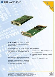
The <strong>NPMC</strong>-<strong>8E1</strong>/<strong>T1</strong>/<strong>J1</strong> is a high performance standard CPU PCI Mezzanine Card<br />
Type 1. It can be plugged onto any carrier board supporting PMC standards:<br />
Figure 1: <strong>NPMC</strong>-<strong>8E1</strong>/<strong>T1</strong>/<strong>J1</strong> on a carrier board (VMEbus, cPCI)<br />
Backplane Connectors<br />
<strong>NPMC</strong>-STM1<br />
(Back View)<br />
<strong>NPMC</strong>-<strong>8E1</strong>/<strong>T1</strong>/<strong>J1</strong><br />
(Back View)<br />
Version 1.1 © N.A.T. GmbH 7
<strong>NPMC</strong>-<strong>8E1</strong>/<strong>T1</strong>/<strong>J1</strong> – Technical Reference Manual<br />
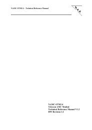
The <strong>NPMC</strong>-<strong>8E1</strong>/<strong>T1</strong>/<strong>J1</strong> has the following major features on-board:<br />
• 8 x E1 / <strong>T1</strong> / <strong>J1</strong> primary rate line interface<br />
• Front-panel I/O<br />
• 32 bit / 66 MHz PCI Bus interface Rev. 2.2<br />
• H.110 / SCSA TSI bus<br />
PCI<br />
Bus<br />
H.110-<br />
SCbus<br />
32 bit<br />
<strong>NPMC</strong>-<strong>8E1</strong>/<strong>T1</strong>/<strong>J1</strong><br />
Figure 2: <strong>NPMC</strong>-<strong>8E1</strong>/<strong>T1</strong>/<strong>J1</strong> Block Diagram<br />
PCI<br />
Bridge<br />
ACEX<br />
FPGA<br />
TSI<br />
Cyclone<br />
FPGA<br />
PLL<br />
ZL30100<br />
ISA Bus<br />
local TDM bus<br />
IDT<br />
82P2288<br />
Octal<br />
E1/<strong>T1</strong>/<strong>J1</strong><br />
Version 1.1 © N.A.T. GmbH 8<br />
Filter<br />
Filter<br />
Filter<br />
Filter<br />
Filter<br />
Filter<br />
Filter<br />
Filter
<strong>NPMC</strong>-<strong>8E1</strong>/<strong>T1</strong>/<strong>J1</strong> – Technical Reference Manual<br />
1.1 Board Features<br />
• Interfaces<br />
PCI: The <strong>NPMC</strong>-<strong>8E1</strong>/<strong>T1</strong>/<strong>J1</strong> includes a 32 bit 33 MHz PCI bus interface. This<br />
is implemented by an FPGA solution based on an Altera ACEX device.<br />
H.110/SCSA: The <strong>NPMC</strong>-<strong>8E1</strong>/<strong>T1</strong>/<strong>J1</strong> implements a 32 bit H.110 interface, which<br />
includes a SCbus interface on I/O-connector P14 according to PMC<br />
specifications. This is implemented by an Altera Cyclone FPGA device.<br />
The H.110 interface is also available on PMC connector P13 according to<br />
PTMC configurations 3 and 5. PTID coding is configuration 5.<br />
SPI: The <strong>NPMC</strong>-<strong>8E1</strong>/<strong>T1</strong>/<strong>J1</strong> implements a SPI bus interface on the PMC I/O<br />
connector P14, which connects to the Altera Cyclone FPGA.<br />
• I/O<br />
E1/<strong>T1</strong>/<strong>J1</strong>: The module carries a IDT 82P2288 framer, which implements eight<br />
E1/<strong>T1</strong>/<strong>J1</strong> interfaces.<br />
Version 1.1 © N.A.T. GmbH 9
<strong>NPMC</strong>-<strong>8E1</strong>/<strong>T1</strong>/<strong>J1</strong> – Technical Reference Manual<br />
1.2 Board Specification<br />
Table 2: <strong>NPMC</strong>-<strong>8E1</strong>/<strong>T1</strong>/<strong>J1</strong> Features<br />
PMC-Module Standard PCI Mezzanine Card Type 1<br />
Front-I/O 4 RJ45 connectors<br />
Rear-I/O H.110 and SCbus (32 bit) on P14, support of PTMC interface<br />
configurations 3 and 5 on P13. PTID coding is configuration 5.<br />
PCI to PMC bus<br />
bridge<br />
Altera ACEX 1K10 FPGA<br />
H.110 TSI Altera Cyclone 1C12 FPGA<br />
Firmware OK1, VxWorks driver (on request)<br />
Power consumption 3.3V 1.0A typ.<br />
Environmental<br />
conditions<br />
5.0V 0.1A typ.<br />
Temperature (operating):<br />
Temperature (storage):<br />
Humidity:<br />
0°C to +60°C with forced cooling<br />
-40°C to +85°C<br />
10 % to 90 % rh noncondensing<br />
Standards compliance PCI Rev. 2.2<br />
IEEE P1386.1 / Draft 2.4a, PICMG 2.15 R1.0<br />
Version 1.1 © N.A.T. GmbH 10
<strong>NPMC</strong>-<strong>8E1</strong>/<strong>T1</strong>/<strong>J1</strong> – Technical Reference Manual<br />
2 Installation<br />
2.1 Safety Note<br />
CAUTION<br />
To ensure proper functioning of the <strong>NPMC</strong>-<strong>8E1</strong>/<strong>T1</strong>/<strong>J1</strong> during its usual lifetime<br />
take the following precautions before handling the board.<br />
Electrostatic discharge and incorrect board installation and uninstallation can<br />
damage circuits or shorten their lifetime.<br />
• Before installing or uninstalling the <strong>NPMC</strong>-<strong>8E1</strong>/<strong>T1</strong>/<strong>J1</strong> read this installation<br />
section<br />
• Before installing or uninstalling the <strong>NPMC</strong>-<strong>8E1</strong>/<strong>T1</strong>/<strong>J1</strong>, read the Installation<br />
Guide and the User’s Manual of the carrier board used<br />
• Before installing or uninstalling the <strong>NPMC</strong>-<strong>8E1</strong>/<strong>T1</strong>/<strong>J1</strong> on a carrier board or<br />
both in a rack:<br />
- Check all installed boards and modules for steps that you have to take<br />
before turning on or off the power.<br />
- Take those steps.<br />
- Finally turn on or off the power.<br />
• Before touching integrated circuits ensure to take all require precautions for<br />
handling electrostatic devices.<br />
• Ensure that the <strong>NPMC</strong>-<strong>8E1</strong>/<strong>T1</strong>/<strong>J1</strong> is connected to the carrier board via all<br />
PMC connectors and that the power is available on both PMC connectors<br />
(GND, +5V, and +3,3V).<br />
• When operating the board in areas of strong electromagnetic radiation<br />
ensure that the module<br />
- is bolted the front panel or rack<br />
- and shielded by closed housing<br />
Version 1.1 © N.A.T. GmbH 11
<strong>NPMC</strong>-<strong>8E1</strong>/<strong>T1</strong>/<strong>J1</strong> – Technical Reference Manual<br />
2.2 Installation Prerequisites and Requirements<br />
IMPORTANT<br />
Before powering up<br />
• check this section for installation prerequisites and requirements<br />
2.2.1 Requirements<br />
2.2.2 Power supply<br />
The installation requires only<br />
• a carrier board for connecting the <strong>NPMC</strong>-<strong>8E1</strong>/<strong>T1</strong>/<strong>J1</strong><br />
• power supply<br />
The power supply for the <strong>NPMC</strong>-<strong>8E1</strong>/<strong>T1</strong>/<strong>J1</strong> must meet the following<br />
specifications:<br />
• required for the module:<br />
- +3,3V / 1.0A typical<br />
- +5,0V / 0.1A typical<br />
2.2.3 Automatic Power Up<br />
In the following situations the <strong>NPMC</strong>-<strong>8E1</strong>/<strong>T1</strong>/<strong>J1</strong> will automatically be reset and<br />
proceed with a normal power up.<br />
Voltage sensors<br />
The voltage sensor generates a reset<br />
• when +5V voltage level drops below 4,4V *<br />
• when +5V voltage level rises above 5,6V *<br />
• when +3.3V voltage level drops below 2,65V *<br />
• when +3.3V voltage level rises above 3,9V *<br />
• or when the carrier board signals a PCI Reset<br />
Watchdog (if enabled)<br />
* defined by: “PCI Specification Revision 2.2, Section 4.2.1.1 and Section 4.3.2”<br />
Version 1.1 © N.A.T. GmbH 12
<strong>NPMC</strong>-<strong>8E1</strong>/<strong>T1</strong>/<strong>J1</strong> – Technical Reference Manual<br />
2.3 Statement on Environmental Protection<br />
2.3.1 Compliance to RoHS Directive<br />
Directive 2002/95/EC of the European Comission on the "Restriction of the use of<br />
certain Hazardous Substances in Electrical and Electronic Equipment" (RoHS)<br />
predicts that all electrical and electronic equipment being put on the European market<br />
after June 30th, 2006 must contain lead, mercury, hexavalent chromium,<br />
polybrominated biphenyls (PBB) and polybrominated diphenyl ethers (PBDE) and<br />
cadmium in maximum concentration values of 0.1% respective 0.01% by weight in<br />
homogenous materials only.<br />
As these harzadous substances are currently used with semiconductors, plastics (i.e.<br />
semiconductor packages, connectors) and soldering tin any hardware product is<br />
affected by the RoHS directive if it does not belong to one of the groups of products<br />
exempted from the RoHS directive.<br />
Although many of hardware products of N.A.T. are exempted from the RoHS<br />
directive it is a declared policy of N.A.T. to provide all products fully compliant to the<br />
RoHS directive as soon as possible. For this purpose since January 31st, 2005 N.A.T.<br />
is requesting RoHS compliant deliveries from its suppliers. Special attention and care<br />
has been payed to the production cycle, so that whereever and whenever possible<br />
RoHS components are used with N.A.T. hardware products already.<br />
2.3.2 Compliance to WEEE Directive<br />
Directive 2002/95/EC of the European Comission on "Waste Electrical and Electronic<br />
Equipment" (WEEE) predicts that every manufacturer of electrical and electronical<br />
equipment which is put on the European market has to contribute to the reuse,<br />
recycling and other forms of recovery of such waste so as to reduce disposal.<br />
Moreover this directive refers to the Directive 2002/95/EC of the European Comission<br />
on the "Restriction of the use of certain Hazardous Substances in Electrical and<br />
Electronic Equipment" (RoHS).<br />
Having its main focus on private persons and households using such electrical and<br />
electronic equipment the directive also affects business-to-business relationships. The<br />
directive is quite restrictive on how such waste of private persons and households has<br />
to be handled by the supplier/manufacturer, however, it allows a greater flexibility in<br />
business-to-business relationships. This pays tribute to the fact with industrial use<br />
electrical and electronical products are commonly intergrated into larger and more<br />
complex envionments or systems that cannot easily be split up again when it comes to<br />
their disposal at the end of their life cycles.<br />
Version 1.1 © N.A.T. GmbH 13
<strong>NPMC</strong>-<strong>8E1</strong>/<strong>T1</strong>/<strong>J1</strong> – Technical Reference Manual<br />
As N.A.T. products are solely sold to industrial customers, by special arrangement at<br />
time of purchase the customer agreed to take the responsibility for a WEEE compliant<br />
disposal of the used N.A.T. product. Moreover, all N.A.T. products are marked<br />
according to the directive with a crossed out bin to indicate that these products within<br />
the European Community must not be disposed with regular waste.<br />
If you have any questions on the policy of N.A.T. regarding the Directive 2002/95/EC<br />
of the European Comission on the "Restriction of the use of certain Hazardous<br />
Substances in Electrical and Electronic Equipment" (RoHS) or the Directive<br />
2002/95/EC of the European Comission on "Waste Electrical and Electronic<br />
Equipment" (WEEE) please contact N.A.T. by phone or e-mail.<br />
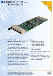
2.4 Location Overview<br />
The figure 3 "Location diagram of the <strong>NPMC</strong>-<strong>8E1</strong>/<strong>T1</strong>/<strong>J1</strong>" highlights the position of the<br />
important components. Depending on the board type it might be that the board does not<br />
include all components named in the location diagram.<br />
PCI-Bus<br />
PCI-I/O<br />
Figure 3: Location diagram of the <strong>NPMC</strong>-<strong>8E1</strong>/<strong>T1</strong>/<strong>J1</strong><br />
PCI<br />
Bridge<br />
PLL<br />
TSI<br />
IDT<br />
82P2288<br />
E1/<strong>T1</strong><br />
Line<br />
Interface<br />
RJ45<br />
RJ45<br />
RJ45<br />
RJ45<br />
Version 1.1 © N.A.T. GmbH 14
<strong>NPMC</strong>-<strong>8E1</strong>/<strong>T1</strong>/<strong>J1</strong> – Technical Reference Manual<br />
3 Functional Blocks<br />
The <strong>NPMC</strong>-<strong>8E1</strong>/<strong>T1</strong>/<strong>J1</strong> can be divided into a number of functional blocks, which are<br />
described in the following paragraphs.<br />
3.1 PCI Interface<br />
The <strong>NPMC</strong>-<strong>8E1</strong>/<strong>T1</strong>/<strong>J1</strong> includes a 32 bit, 33 MHz PCI interface to connect to the carrier<br />
board. This is implemented by an Altera ACEX 1K10 FPGA. This FPGA transfers to an ISA<br />
– like bus, which connects to the framer and to the TSI FPGA, which implements the TDM<br />
TSI and some control/status registers.<br />
3.2 H.110 Bus Controller and Line Interfaces<br />
3.2.1 Block Diagramm of the TDM Structure<br />
Figure 4: Local TDM Bus Organisation and Synchronisation<br />
82P2288<br />
8<br />
Framers<br />
local TDM bus<br />
16 lines, 2 lines<br />
to each framer<br />
L_CLK, L_FS<br />
FPGA<br />
TSI<br />
H.110<br />
H.110 &<br />
SCbus<br />
PMC<br />
I/O<br />
P13<br />
PMC<br />
I/O<br />
P14<br />
Version 1.1 © N.A.T. GmbH 15
<strong>NPMC</strong>-<strong>8E1</strong>/<strong>T1</strong>/<strong>J1</strong> – Technical Reference Manual<br />
3.2.2 Description of the TDM Structure<br />
The TDM data are routed through the Altera Cyclone FPGA device, which implements a TSI<br />
device. Hence, any timeslot switching between H.110/SC bus and framer is possible. Local<br />
TDM data lines TDM[0 – 15] are routed between the framer and the TSI. The TSI device<br />
derives its time base either from the H.110/SC bus or from the framer. From this input it<br />
generates local clock and frame sync for the framer to synchronize to. Hence, the TSI<br />
implemented in the FPGA may be clock slave or clock master to the H.110 or SCbus on the<br />
carrier module. The sync and clock signals L_FS and L_CLK can be programmed within the<br />
FPGA control register settings.<br />
The connection between the TDM data lines LD[0 – 15] and the corresponding serial<br />
channels Rx/Tx of the framer is shown in the following Table 3:<br />
Table 3: TDM Channel �� Framer Serial Data Line Connection<br />
TSI local<br />
TDM<br />
Channel<br />
3.2.3 SCbus Compatibility<br />
Framer serial<br />
channel<br />
TSI local<br />
TDM<br />
Channel<br />
Framer serial<br />
channel<br />
LD8 RxSER1 LD0 TxSER1<br />
LD9 RxSER2 LD1 TxSER2<br />
LD10 RxSER3 LD2 TxSER3<br />
LD11 RxSER4 LD3 TxSER4<br />
LD12 RxSER5 LD4 TxSER5<br />
LD13 RxSER6 LD5 TxSER6<br />
LD14 RxSER7 LD6 TxSER7<br />
LD15 RxSER8 LD7 TxSER8<br />
The SCbus implemented on the <strong>NPMC</strong>-<strong>8E1</strong>/<strong>T1</strong>/<strong>J1</strong> is a sub-set of the H.110 bus. SCbus data<br />
lines correspond to H.110 data lines CT_D[0 – 15]. On the <strong>NPMC</strong>-<strong>8E1</strong>/<strong>T1</strong>/<strong>J1</strong>, the bus width<br />
has been extended to 32 bit, in order to make use of all the 32 data lines switching capabilities<br />
of the TSI device. See chapter 5 (PMC P14 Connector) for reference.<br />
3.2.4 E1/<strong>T1</strong>/<strong>J1</strong> Line Interfaces<br />
The eight E1/<strong>T1</strong>/<strong>J1</strong> interfaces connect the IDT 82P2288 framer to the front panel RJ45<br />
connectors. Timing and interface characteristics can be set up by software within the<br />
82P2288. The line interface is conform to EN60950 and G.703.<br />
Version 1.1 © N.A.T. GmbH 16
<strong>NPMC</strong>-<strong>8E1</strong>/<strong>T1</strong>/<strong>J1</strong> – Technical Reference Manual<br />
4 Hardware<br />
4.1 Memory Map<br />
Addresses are defined by programming the base and translation address registers which<br />
reside in the PCI configuration space of the ACEX FPGA PCI bridge. This setting may<br />
be done by the user application-specific. Hence, the table below shows just an example,<br />
which may be altered depending on the user’s needs. The memory window used to<br />
decode the devices given below requires 256kB in size.<br />
Table 4: Memory Map<br />
Device Address Offset Access Function<br />
PCI FPGA 0x0000.0000 16 bit r/w I/O register access<br />
reserved 0x0001.0000 reserved reserved<br />
TSI FPGA 0x0002.0000 16 bit r/w TSI FPGA register access, routing memory<br />
Framer 0x0003.0000 8 bit r/w Framer register access<br />
4.2 Interrupts<br />
The <strong>NPMC</strong>-<strong>8E1</strong>/<strong>T1</strong>/<strong>J1</strong> wire-or’s the framer interrupt and the TSI interrupt to the PMC<br />
/INTA signal. Each of these interrupts is software maskable not only in the framer and<br />
TSI devices themselves, but also in the PCI-FPGA, through which these interrupts are<br />
routed. By default, the interrupts are masked (disabled). Refer to chapter 4.3 for details<br />
on the PCI FPGA control/status registers.<br />
Version 1.1 © N.A.T. GmbH 17
<strong>NPMC</strong>-<strong>8E1</strong>/<strong>T1</strong>/<strong>J1</strong> – Technical Reference Manual<br />
4.3 Registers<br />
4.3.1 I/O Register Overview<br />
The following table gives an overview of all registers contained in the PCI-FPGA:<br />
Table 5: I/O Register<br />
Address Name Access Description<br />
0x00 VER r Version Register<br />
0x02 IRQ_Mask r/w Interrupt Mask Register (set ‘1’ to enable Int.)<br />
0x04 IRQ_Status r Interrupt Status Register (shows actual state of IRQ;<br />
‘1’ showing Interrupt is asserted)<br />
0x06 reserved - reserved<br />
4.3.2 Version Register<br />
The Version Register shows the actual PCB and PCI-FPGA releases.<br />
Table 6: Version Register<br />
VER - Address 0x00<br />
Default value 0x1010<br />
Bit 15 14 13 12 11 10 9 8 7 6 5 4 3 2 1 0<br />
Access R R R R R R R R R R R R R R R R<br />
Func PCB Version FPGA Version<br />
There is a 16 bit wide I/O-register that holds the PCB revision and the PCI-FPGA version<br />
implemented in the PCI-FPGA onboard the <strong>NPMC</strong>-<strong>8E1</strong>/<strong>T1</strong>/<strong>J1</strong>, which contains the revision<br />
code of the PCB in the bits [15-8] and the revision code of the PCI-FPGA in bits [7-0]. This<br />
code reads decimally-coded in 2 nibbles, i.e. the PCB version V1.0 reads 0x10. The register is<br />
addressed by address offset 0x0.<br />
Version 1.1 © N.A.T. GmbH 18
<strong>NPMC</strong>-<strong>8E1</strong>/<strong>T1</strong>/<strong>J1</strong> – Technical Reference Manual<br />
4.3.3 IRQ_Mask – Interrupt Mask Register<br />
The Interrupt Mask Register allows the individual masking of the interrupt sources. Interrupt<br />
sources which are enabled are wired or’ed to the PCI /INTA pin, thus leading to an PCI<br />
interrupt. The source for the interrupt can be read from the IRQ-Status register.<br />
The meaning of the individual bits is explained in Table 10.<br />
Table 7: IRQ_Mask Register<br />
IRQ_Mask - Address 0x02<br />
Default value 0x0000<br />
Bit 15 14 13 12 11 10 9 8 7 6 5 4 3 2 1 0<br />
Access R R R R R R R R R R R R R R R/W R/W<br />
Func - - - - - - - - - - - - - -<br />
0 = Interrupt is disabled<br />
1 = Interrupt is enabled<br />
4.3.4 IRQ_Stat – Interrupt Status Register<br />
By means of the IRQ_Stat register the status of the interrupt lines of the individual onboard<br />
interrupt sources can be determined. The value of a bit does not depend on the setting of the<br />
corresponding bit in the IRQ_Mask register. If a bit in the IRQ_Stat register is set (meaning<br />
Interrupt is asserted) and the corresponding bit in the IRQ_Mask register is enabled, the PCI<br />
interrupt line /INTA will be activated.<br />
The following table shows the assignment of the register bits.<br />
Table 8: IRQ_Stat Register<br />
IRQ_Stat - Address 0x04<br />
Default value 0x0000<br />
Bit 15 14 13 12 11 10 9 8 7 6 5 4 3 2 1 0<br />
Access R R R R R R R R R R R R R R R R<br />
Func - - - - - - - - - - - - - -<br />
0 = no Interrupt asserted<br />
1 = Interrupt is asserted<br />
Version 1.1 © N.A.T. GmbH 19<br />
IRQ<br />
TSI<br />
IRQ<br />
TSI<br />
IRQ<br />
Framer<br />
IRQ<br />
Framer
<strong>NPMC</strong>-<strong>8E1</strong>/<strong>T1</strong>/<strong>J1</strong> – Technical Reference Manual<br />
4.4 Front Panel and LEDs<br />
The <strong>NPMC</strong>-<strong>8E1</strong>/<strong>T1</strong>/<strong>J1</strong> module is equipped with 4 LEDs, which are completely software<br />
programmable. Thus their functionality depends very much of the application running on the<br />
module.<br />
N.A.T.<br />
LINE 0/1<br />
LINE 2/3<br />
4 3 2 1<br />
LINE 4/5<br />
LINE 6/7<br />
<strong>NPMC</strong>-<strong>8E1</strong><br />
Figure 5: Front Panel and LEDs<br />
LEDs:<br />
LED 1 - 4 the green LEDs 1 – 4 are fully software<br />
programmable and their meaning depends<br />
on user application.<br />
Connectors:<br />
LINE 0/1, These RJ45 connectors S1 – S4 carry<br />
LINE 2/3, the 8 E1/<strong>T1</strong>/<strong>J1</strong> interfaces. Each 2<br />
LINE 4/5, interfaces share one connector.<br />
LINE 6/7<br />
Please refer to Chapter 5.10 for details on front panel<br />
connectors.<br />
Version 1.1 © N.A.T. GmbH 20
<strong>NPMC</strong>-<strong>8E1</strong>/<strong>T1</strong>/<strong>J1</strong> – Technical Reference Manual<br />
5 Connectors<br />
5.1 Connector Overview<br />
P<br />
12<br />
P<br />
14<br />
P<br />
11<br />
P<br />
13<br />
Figure 6: Connectors of the <strong>NPMC</strong>-<strong>8E1</strong>/<strong>T1</strong>/<strong>J1</strong><br />
1<br />
SW1<br />
1<br />
JP3<br />
JP1<br />
1<br />
JP2<br />
S4<br />
S3<br />
S2<br />
S1<br />
Please refer to the following tables to look up the pin assignment of the <strong>NPMC</strong>-<strong>8E1</strong>/<strong>T1</strong>/<strong>J1</strong>.<br />
Version 1.1 © N.A.T. GmbH 21
<strong>NPMC</strong>-<strong>8E1</strong>/<strong>T1</strong>/<strong>J1</strong> – Technical Reference Manual<br />
5.2 Connector JP1: TSI_FPGA JTAG Port<br />
Connector JP1 connects the JTAG-port of the TSI-FPGA device.<br />
Pin No.<br />
Table 9: TSI_FPGA JTAG port<br />
Signal Signal Pin No.<br />
1 TCK_A GND 2<br />
3 TDO_A +3.3V 4<br />
5 TMS_A nc 6<br />
7 nc nc 8<br />
9 TDI_A GND 10<br />
5.3 Connector JP2: TSI_FPGA Programming Port<br />
Connector JP1 connects the programming-port of the TSI-FPGA device. It is used to program<br />
the serial EEPROM that stores the configuration-data of the TSI-FPGA.<br />
Table 10: TSI_FPGA programming port<br />
Pin No.<br />
Signal Signal Pin No.<br />
1 DCLK GND 2<br />
3 CONF_DONE +3.3V 4<br />
5 /CONFIG /CECONF 6<br />
7 DATAO /CSO 8<br />
9 ASDI GND 10<br />
Version 1.1 © N.A.T. GmbH 22
<strong>NPMC</strong>-<strong>8E1</strong>/<strong>T1</strong>/<strong>J1</strong> – Technical Reference Manual<br />
5.4 Connector JP3: TSI_FPGA JTAG Port<br />
Connector JP3 connects the JTAG- or programming-port of the PCI-FPGA device. It is used<br />
to either access the PCI-FPGA itself, or to program the serial EEPROM that stores the<br />
configuration-data of the PCI-FPGA.<br />
Pin No.<br />
Table 11: TSI_FPGA JTAG port<br />
Signal Signal Pin No.<br />
1 TCK_B GND 2<br />
3 TDO_B +3.3V 4<br />
5 TMS_B nc 6<br />
7 nc nc 8<br />
9 TDI_B GND 10<br />
5.5 DIL Switch SW1: Reserved for future use<br />
This dual DIL Switch may be used in future versions of the <strong>NPMC</strong>-<strong>8E1</strong>/<strong>T1</strong>/<strong>J1</strong>.<br />
Version 1.1 © N.A.T. GmbH 23
<strong>NPMC</strong>-<strong>8E1</strong>/<strong>T1</strong>/<strong>J1</strong> – Technical Reference Manual<br />
5.6 PMC Connector P11<br />
Pin No.<br />
Table 12: PMC Connector P11<br />
PCI-Signal PCI-Signal Pin No.<br />
1 TCK -12V 2<br />
3 GND /INT A 4<br />
5 /INT B /INT C 6<br />
7 /BUSMODE1 +5V 8<br />
9 /INT D PCI_RSV1 10<br />
11 GND 3.3Vaux 12<br />
13 CLK GND 14<br />
15 GND /GNT 16<br />
17 /REQ +5V 18<br />
19 V (I/O) AD31 20<br />
21 AD28 AD22 22<br />
23 AD25 GND 24<br />
25 GND CBE3 26<br />
27 AD22 AD21 28<br />
29 AD19 +5V 30<br />
31 V (I/O) AD17 32<br />
33 /FRAME GND 34<br />
35 GND /IRDY 36<br />
37 /DEVSEL +5V 38<br />
39 GND /LOCK 40<br />
41 /SDONE /SB0 42<br />
43 PAR GND 44<br />
45 V (I/O) AD15 46<br />
47 AD12 AD11 48<br />
49 AD09 +5V 50<br />
51 GND /CBE0 52<br />
53 AD06 AD05 54<br />
55 AD04 GND 56<br />
57 V (I/O) AD03 58<br />
59 AD02 AD01 60<br />
61 AD00 +5V 62<br />
63 GND /REQ64 64<br />
Pins for –12V, Vaux, and V(I/O) are not connected to the module. The same applies to JTAG<br />
signal TCK and PCI signals /LOCK, /SDONE, /SBO, /INTB, /INTC, /INTD. The PCI bridge<br />
chip always drives signals to 3.3V level, but it 5V tolerant.<br />
Version 1.1 © N.A.T. GmbH 24
<strong>NPMC</strong>-<strong>8E1</strong>/<strong>T1</strong>/<strong>J1</strong> – Technical Reference Manual<br />
5.7 PMC Connector P12<br />
Pin No.<br />
Table 13: PMC Connector P12<br />
PCI-Signal PCI-Signal Pin No.<br />
1 +12V /TRST 2<br />
3 TMS TDO 4<br />
5 TDI GND 6<br />
7 GND PCI_RSV3 8<br />
9 PCI_RSV PCI_RSV4 10<br />
11 /BUSMODE2 +3.3V 12<br />
13 /PCIRST /BUSMODE3 14<br />
15 +3.3V /BUSMODE4 16<br />
17 /PME GND 18<br />
19 AD30 AD29 20<br />
21 GND AD26 22<br />
23 AD24 +3.3V 24<br />
25 IDSEL AD23 26<br />
27 +3.3V AD20 28<br />
29 AD18 GND 30<br />
31 AD16 /CBE2 32<br />
33 GND PCI_RESVD 34<br />
35 /TRDY +3.3V 36<br />
37 GND /STOP 38<br />
39 /PERR GND 40<br />
41 +3.3V /SERR 42<br />
43 /CBE1 GND 44<br />
45 AD14 AD13 46<br />
47 M66EN AD10 48<br />
49 AD08 +3.3V 50<br />
51 AD07 PCI_RESV 52<br />
53 +3.3V PCI_RESV 54<br />
55 PCI_RESV GND 56<br />
57 PCI_RESV PCI_RESV 58<br />
59 GND PCI_RESV 60<br />
61 ACK64 +3.3V 62<br />
63 GND PCI_RESV 64<br />
Pins for +12V and /BUSMODE2 are not connected to the module. The same applies to JTAG<br />
signals TMS and /TRST. JTAG TDI is connected to TDO.<br />
Version 1.1 © N.A.T. GmbH 25
<strong>NPMC</strong>-<strong>8E1</strong>/<strong>T1</strong>/<strong>J1</strong> – Technical Reference Manual<br />
5.8 PMC Connector P13 ( PTMC Option H.110 )<br />
Table 14: PMC Connector P13<br />
ext. Signal<br />
Pin No. Pin No. ext. Signal<br />
CT_D26 1 2 GND<br />
GND 3 4 -<br />
CT_D24 5 6 -<br />
CT_D22 7 8 GND<br />
V(I/O) 9 10 CT_D31<br />
GNDZ11 11 12 CT_D29<br />
CT_D20 13 14 GND<br />
GND 15 16 CT_D27<br />
CT_FRAME_A 17 18 CT_D25<br />
CT_FRAME_B 19 20 GND<br />
V(I/O) 21 22 CT_D23<br />
GNDZ23 23 24 CT_D21<br />
CT_C8_A 25 26 GND<br />
GND 27 28 CT_D19<br />
CT_D18 29 30 CT_D17<br />
CT_D16 31 32 GND<br />
GND 33 34 CT_NETR2<br />
CT_D14 35 36 CT_D30<br />
CT_D12 37 38 GND<br />
/PTEN 39 40 CT_D28<br />
GNDZ41 41 42 CT_NETR1<br />
CT_C8_B 43 44 GND<br />
GND 45 46 CT_D15<br />
CT_D10 47 48 CT_D13<br />
CT_D8 49 50 CT_D11<br />
GND 51 52 CT_D9<br />
CT_D7 53 54 CT_D6<br />
CT_D4 55 56 GND<br />
- 57 58 CT_D5<br />
CT_D2 59 60 CT_D3<br />
CT_D1 61 62 GND<br />
GND 63 64 CT_D1<br />
Version 1.1 © N.A.T. GmbH 26
<strong>NPMC</strong>-<strong>8E1</strong>/<strong>T1</strong>/<strong>J1</strong> – Technical Reference Manual<br />
5.9 PMC Connector P14 ( PMC I/O )<br />
ext. Signal<br />
Table 15: PMC Connector P14<br />
Pin No. PCI-Signal PCI-Signal Pin No. ext. Signal<br />
MC 1 I/O I/O 2 CT_D15<br />
CT_D14 3 I/O I/O 4 CT_D13<br />
CT_D12 5 I/O I/O 6 GND<br />
CT_D11 7 I/O I/O 8 CT_D10<br />
CT_D09 9 I/O I/O 10 CT_D8<br />
CT_D07 11 I/O I/O 12 GND<br />
CT_D06 13 I/O I/O 14 CT_D5<br />
CT_D04 15 I/O I/O 16 CT_D3<br />
CT_D02 17 I/O I/O 18 CT_D1<br />
GND 19 I/O I/O 20 CT_D0<br />
CLKFAIL 21 I/O I/O 22 /FSYNC<br />
SREF_8K 23 I/O I/O 24 SCLK<br />
GND 25 I/O I/O 26 /SCLKx2<br />
SL_4 27 I/O I/O 28 /C16+<br />
SL_2 29 I/O I/O 30 SL_3<br />
SL_0 31 I/O I/O 32 SL_1<br />
SPICLK 33 I/O I/O 34 /SPISEL<br />
SPIMISO 35 I/O I/O 36 SPIMOSI<br />
/C16- 37 I/O I/O 38 CT_FRAME_B<br />
CT_FRAME_A 39 I/O I/O 40 CT_NETREF2<br />
CT_NETREF1 41 I/O I/O 42 /C4<br />
C2 43 I/O I/O 44 GND<br />
CT_C8_B 45 I/O I/O 46 CT_C8_A<br />
CT_D16 47 I/O I/O 48 CT_D17<br />
CT_D18 49 I/O I/O 50 CT_D19<br />
GND 51 I/O I/O 52 CT_D20<br />
CT_D21 53 I/O I/O 54 CT_D22<br />
CT_D23 55 I/O I/O 56 CT_D24<br />
GND 57 I/O I/O 58 CT_D25<br />
CT_D26 59 I/O I/O 60 CT_D27<br />
CT_D28 61 I/O I/O 62 CT_D29<br />
CT_D30 63 I/O I/O 64 CT_D31<br />
The SCbus implemented on the <strong>NPMC</strong>-<strong>8E1</strong>/<strong>T1</strong>/<strong>J1</strong> is a sub-set of the H.110 bus. SCbus data<br />
lines correspond to H.110 data lines CT_D0 – 15.<br />
Version 1.1 © N.A.T. GmbH 27
<strong>NPMC</strong>-<strong>8E1</strong>/<strong>T1</strong>/<strong>J1</strong> – Technical Reference Manual<br />
5.10 The Front Panel Connectors (S1 – S4)<br />
Figure 7: The E1/<strong>T1</strong> Connector<br />
1 8<br />
Table 16: Pin Assignment of the E1/<strong>T1</strong> connectors<br />
Pin<br />
Signal<br />
1 TXa+ Output<br />
2 TXa- Output<br />
3 TXb+ Output<br />
4 RXb+ Input<br />
5 RXb- Input<br />
6 TXb- Output<br />
7 RXa+ Input<br />
8 RXa- Input<br />
TXa/RXa refer to the first line interface on the respectice connector.<br />
Version 1.1 © N.A.T. GmbH 28
<strong>NPMC</strong>-<strong>8E1</strong>/<strong>T1</strong>/<strong>J1</strong> – Technical Reference Manual<br />
6 Known Bugs / Restrictions<br />
none<br />
Version 1.1 © N.A.T. GmbH 29
<strong>NPMC</strong>-<strong>8E1</strong>/<strong>T1</strong>/<strong>J1</strong> – Technical Reference Manual<br />
Appendix A: Reference Documentation<br />
[1] IDT, Octal <strong>T1</strong>/E1/<strong>J1</strong> Long Haul / Short Haul Transceiver IDT82P2288, 3/2004, Rev. 3<br />
[2] Altera, ACEX 1K Programmable Logic Device Family, May 2003, ver. 2.4 data sheet<br />
[3] Altera, Cyclone FPGA Family Data Sheet, Oct. 2003, ver. 1.2<br />
Version 1.1 © N.A.T. GmbH 30
<strong>NPMC</strong>-<strong>8E1</strong>/<strong>T1</strong>/<strong>J1</strong> – Technical Reference Manual<br />
Appendix B: Document’s History<br />
Revision Date Description Author<br />
1.0 21.11.2005 initial revision ga<br />
1.1 10.02.2006 ‘Statement on Environmental Protection’ added ga<br />
Version 1.1 © N.A.T. GmbH 31