NAT-MCH Users Manual Version 1.16
NAT-MCH Users Manual Version 1.16
NAT-MCH Users Manual Version 1.16

You also want an ePaper? Increase the reach of your titles
YUMPU automatically turns print PDFs into web optimized ePapers that Google loves.
<strong>NAT</strong>-<strong>MCH</strong> – <strong>Users</strong> <strong>Manual</strong><br />
<strong>NAT</strong>-<strong>MCH</strong><br />
<strong>Users</strong> <strong>Manual</strong><br />
<strong>Version</strong> <strong>1.16</strong>
<strong>NAT</strong>-<strong>MCH</strong> – <strong>Users</strong> <strong>Manual</strong><br />
<strong>NAT</strong>-<strong>MCH</strong> has been designed by:<br />
N.A.T. GmbH<br />
Kamillenweg 22<br />
D-53757 Sankt Augustin<br />
Phone: ++49/2241/3989-0<br />
Fax: ++49/2241/3989-10<br />
E-Mail: sales@nateurope.com<br />
Internet: http://www.nateurope.com<br />
<strong>Version</strong> <strong>1.16</strong> © N.A.T. GmbH 2
<strong>NAT</strong>-<strong>MCH</strong> – <strong>Users</strong> <strong>Manual</strong><br />
Disclaimer<br />
The following documentation, compiled by N.A.T. GmbH (henceforth called N.A.T.),<br />
represents the current status of the product’s development. The documentation is updated on a<br />
regular basis. Any changes which might ensue, including those necessitated by updated<br />
specifications, are considered in the latest version of this documentation. N.A.T. is under no<br />
obligation to notify any person, organization, or institution of such changes or to make these<br />
changes public in any other way.<br />
We must caution you, that this publication could include technical inaccuracies or<br />
typographical errors.<br />
N.A.T. offers no warranty, either expressed or implied, for the contents of this documentation<br />
or for the product described therein, including but not limited to the warranties of<br />
merchantability or the fitness of the product for any specific purpose.<br />
In no event, will N.A.T. be liable for any loss of data or for errors in data utilization or<br />
processing resulting from the use of this product or the documentation. In particular, N.A.T.<br />
will not be responsible for any direct or indirect damages (including lost profits, lost savings,<br />
delays or interruptions in the flow of business activities, including but not limited to, special,<br />
incidental, consequential, or other similar damages) arising out of the use of or inability to use<br />
this product or the associated documentation, even if N.A.T. or any authorized N.A.T.<br />
representative has been advised of the possibility of such damages.<br />
The use of registered names, trademarks, etc. in this publication does not imply, even in the<br />
absence of a specific statement, that such names are exempt from the relevant protective laws<br />
and regulations (patent laws, trade mark laws, etc.) and therefore free for general use. In no<br />
case does N.A.T. guarantee that the information given in this documentation is free of such<br />
third-party rights.<br />
Neither this documentation nor any part thereof may be copied, translated or reduced to any<br />
electronic medium or machine form without the prior written consent from N.A.T. GmbH.<br />
This product (and the associated documentation) is governed by the N.A.T. General<br />
Conditions and Terms of Delivery and Payment.<br />
<strong>Version</strong> <strong>1.16</strong> © N.A.T. GmbH 3
<strong>NAT</strong>-<strong>MCH</strong> – <strong>Users</strong> <strong>Manual</strong><br />
Table of Contents<br />
DISCLAIMER....................................................................................................................................................... 3<br />
TABLE OF CONTENTS...................................................................................................................................... 4<br />
LIST OF FIGURES .............................................................................................................................................. 7<br />
LIST OF TABLES ................................................................................................................................................ 7<br />
1 BOARD SPECIFICATION...................................................................................................................... 10<br />
1.1 <strong>NAT</strong>-<strong>MCH</strong> FEATURES ....................................................................................................................... 11<br />
1.1.1 CPU and Memory ......................................................................................................................... 11<br />
1.1.2 IPMI and Management.................................................................................................................. 11<br />
1.1.3 Supported Fabrics and Compliance.............................................................................................. 11<br />
1.1.4 Clock Distribution......................................................................................................................... 11<br />
1.1.5 External Clock Reference Input .................................................................................................... 11<br />
1.1.6 LEDs.............................................................................................................................................. 12<br />
2 OVERVIEW: <strong>NAT</strong>-<strong>MCH</strong> PRODUCT FAMILY................................................................................... 13<br />
2.1 <strong>NAT</strong>-<strong>MCH</strong> VARIANTS ....................................................................................................................... 14<br />
2.2 <strong>NAT</strong>-<strong>MCH</strong> GEN2: CONNECTORS AND INDICATORS AT THE FACE PLATE........................................... 16<br />
2.2.1 LED Indicators.............................................................................................................................. 16<br />
2.2.2 SMA Connector – External Clock Reference ................................................................................ 17<br />
2.2.3 100 BaseT interface – primary Management Interface Port......................................................... 17<br />
2.2.4 GigaBit Ethernet (GbE) Uplink Port............................................................................................. 17<br />
2.2.5 Console (Dbg) Port....................................................................................................................... 17<br />
2.3 <strong>NAT</strong>-<strong>MCH</strong> GEN3: CONNECTORS AND INDICATORS AT THE FACE PLATE........................................... 18<br />
2.3.1 LED Indicators.............................................................................................................................. 18<br />
2.3.2 SMA Connectors – External Clock Reference............................................................................... 19<br />
2.3.3 Dual GbE Uplink Port................................................................................................................... 19<br />
2.3.4 Management Interface Port .......................................................................................................... 19<br />
2.3.5 Console Port – USB / Telnet ......................................................................................................... 19<br />
2.4 <strong>NAT</strong>-<strong>MCH</strong>-LC: CONNECTORS AND INDICATORS AT THE FACE PLATE .............................................. 21<br />
2.4.1 LED Indicators.............................................................................................................................. 21<br />
2.4.2 GbE Uplink Port ........................................................................................................................... 21<br />
2.4.3 Management Interface Port .......................................................................................................... 21<br />
2.4.4 Console Port – USB / Telnet ......................................................................................................... 22<br />
3 MEZZANINE MODULE OPTIONS....................................................................................................... 23<br />
3.1.1 Base Module.................................................................................................................................. 23<br />
3.1.2 Clock Modules............................................................................................................................... 24<br />
3.1.3 HUB Mezzanine Modules.............................................................................................................. 24<br />
4 OPERATION............................................................................................................................................. 27<br />
4.1 SYSTEM STARTUP AND REDUNDANCY OPERATION ............................................................................ 27<br />
4.2 AMC MODULE STARTUP SEQUENCING .............................................................................................. 27<br />
4.3 LOCAL SHELF MANAGER.................................................................................................................... 27<br />
4.3.1 Sensor Event Log........................................................................................................................... 28<br />
<strong>Version</strong> <strong>1.16</strong> © N.A.T. GmbH 4
<strong>NAT</strong>-<strong>MCH</strong> – <strong>Users</strong> <strong>Manual</strong><br />
4.3.2 Temperature Management ............................................................................................................ 28<br />
4.4 <strong>NAT</strong>-<strong>MCH</strong>S OPERATING WITH UNMANAGED POWER MODULES ........................................................ 28<br />
5 <strong>MCH</strong> CONFIGURATION........................................................................................................................ 30<br />
5.1 CONFIGURATION VIA CONSOLE PORT ................................................................................................. 30<br />
5.2 CONFIGURATION VIA THE WEB INTERFACE....................................................................................... 31<br />
5.3 CUSTOMIZING THE NETWORK CONFIGURATION ................................................................................. 31<br />
5.4 DISPLAYING AND CHANGING <strong>MCH</strong> OPERATIONAL PARAMETERS ....................................................... 31<br />
5.4.1 <strong>MCH</strong> Global Parameters [3] ........................................................................................................ 32<br />
5.4.2 Shelf Manager Configuration [4].................................................................................................. 34<br />
5.4.3 Carrier Manager Configuration [5] ............................................................................................. 34<br />
5.4.4 SEL Configuration Flags [6] ........................................................................................................ 35<br />
5.4.5 GbE Switch Configuration [7] ...................................................................................................... 35<br />
5.4.6 CLK Module Configuration [8] (optional).................................................................................... 35<br />
5.4.7 PCIe Switch Configuration [9] (optional) .................................................................................... 36<br />
5.4.8 SRIO Switch Configuration [9] (optional).................................................................................... 37<br />
5.4.9 NTP Configuration [10]................................................................................................................ 37<br />
5.4.10 DHCP Configuration [11] ....................................................................................................... 37<br />
6 UPDATING THE <strong>MCH</strong> FIRMWARE.................................................................................................... 38<br />
6.1 FIRMWARE UPDATE FROM WITHIN THE RUNNING <strong>MCH</strong> FIRMWARE ................................................... 38<br />
6.2 FIRMWARE UPDATE FROM BOOTLOADER ........................................................................................... 38<br />
6.3 FIRMWARE UPDATE............................................................................................................................ 38<br />
7 MANAGEMENT INTERFACE............................................................................................................... 40<br />
7.1 SOFTWARE STRUCTURE ...................................................................................................................... 40<br />
7.2 COMMUNICATION BETWEEN HOST SYSTEM AND <strong>MCH</strong> ....................................................................... 42<br />
7.2.1 Remote management control protocol .......................................................................................... 42<br />
7.2.2 Supported IPMI messages............................................................................................................. 42<br />
7.3 HOST SOFTWARE OVERVIEW............................................................................................................... 42<br />
7.3.1 N.A.T. JAVA GUI application ‘NatView’...................................................................................... 42<br />
7.3.2 Ipmitool ......................................................................................................................................... 45<br />
7.3.3 OpenHPI ....................................................................................................................................... 46<br />
8 COMMAND LINE INTERFACE............................................................................................................ 51<br />
9 WEBSERVER ........................................................................................................................................... 55<br />
10 CLOCK MODULE CONFIGURATION................................................................................................ 57<br />
10.1 PLL REFERENCE INPUT CONFIGURATION........................................................................................... 58<br />
10.2 PLL MODE CONFIGURATION.............................................................................................................. 59<br />
10.3 CLOCK TYPE CONFIGURATION ........................................................................................................... 60<br />
10.4 CLOCK OUTPUT CONFIGURATION....................................................................................................... 61<br />
10.5 WRITE CLOCK MODULE REGISTER..................................................................................................... 62<br />
10.6 OR VALUE TO CLOCK MODULE REGISTER......................................................................................... 63<br />
10.7 AND VALUE TO CLOCK MODULE REGISTER...................................................................................... 64<br />
11 HARDWARE RELEASES ....................................................................................................................... 65<br />
11.1 KNOWN HARDWARE ISSUES ............................................................................................................... 65<br />
12 GIVE US A HINT ! ................................................................................................................................... 66<br />
APPENDIX A CONNECTOR PINOUTS................................................................................................. 67<br />
APPENDIX A 1 CONSOLE CONNECTOR – RS232........................................................................................... 67<br />
<strong>Version</strong> <strong>1.16</strong> © N.A.T. GmbH 5
<strong>NAT</strong>-<strong>MCH</strong> – <strong>Users</strong> <strong>Manual</strong><br />
APPENDIX A 2 ETHERNET CONNECTOR – GBE UPLINK ............................................................................... 68<br />
APPENDIX A 3 ETHERNET CONNECTOR – 100 BASET MANAGEMENT PORT................................................ 69<br />
APPENDIX A 4 EXTERNAL CLOCK REFERENCE CONNECTOR ....................................................................... 69<br />
APPENDIX A 5 <strong>NAT</strong>-<strong>MCH</strong> BASE6/12 – CONNECTOR TONGUE 1................................................................. 70<br />
APPENDIX A 6 <strong>NAT</strong>-<strong>MCH</strong>-CLOCK CONNECTOR TONGUE 2 ........................................................................ 73<br />
APPENDIX A 7 <strong>NAT</strong>-<strong>MCH</strong> HUB-MODULE CONNECTOR TONGUE 3............................................................. 76<br />
APPENDIX A 8 <strong>NAT</strong>-<strong>MCH</strong> HUB-MODULE CONNECTOR TONGUE 4............................................................. 79<br />
APPENDIX B <strong>MCH</strong> ACCESS FROM A DIFFERENT SUBNETWORK............................................ 82<br />
APPENDIX B 1 NETWORK SETUP:................................................................................................................. 82<br />
APPENDIX B 2 <strong>MCH</strong> IP ADDRESS CONFIGURATION: .................................................................................... 82<br />
APPENDIX B 3 LINUX GATEWAY CONFIGURATION: ..................................................................................... 83<br />
APPENDIX B 4 TEST1: PING BETWEEN <strong>MCH</strong> AND GATEWAY....................................................................... 84<br />
APPENDIX B 5 TEST2: PING BETWEEN CONTROL HOST AND GATEWAY ........................................................ 84<br />
APPENDIX B 6 TEST3: PING BETWEEN CONTROL HOST AND <strong>MCH</strong>: .............................................................. 85<br />
APPENDIX C N.A.T. DEFINED OEM IPMI MESSAGES ................................................................... 87<br />
APPENDIX C 1 IPMI MESSAGES TO READ AND WRITE REGISTER .................................................................. 87<br />
APPENDIX C 2 REGISTER ACCESS USING IPMITOOL ...................................................................................... 87<br />
DOCUMENT’S HISTORY................................................................................................................................ 89<br />
<strong>Version</strong> <strong>1.16</strong> © N.A.T. GmbH 6
<strong>NAT</strong>-<strong>MCH</strong> – <strong>Users</strong> <strong>Manual</strong><br />
List of Figures<br />
Figure 1 : <strong>NAT</strong>-<strong>MCH</strong> Block Diagram with PCIe Mezzanine Option shown.......................... 13<br />
Figure 2 : <strong>NAT</strong>-<strong>MCH</strong> Front Panel ........................................................................................... 16<br />
Figure 3 : <strong>NAT</strong>-<strong>MCH</strong> Mezzanine Options .............................................................................. 23<br />
Figure 4 : Software structure overview.................................................................................... 40<br />
Figure 5 : Software structure details ........................................................................................ 41<br />
Figure 6 : NatView: Connecting to a MCTA chassis............................................................... 44<br />
Figure 7 : NatView: Main window .......................................................................................... 45<br />
List of Tables<br />
Table 1 : <strong>NAT</strong>-<strong>MCH</strong> Technical Data....................................................................................... 10<br />
Table 2: <strong>MCH</strong> Variants and Features....................................................................................... 15<br />
Table 3 List of CLI commands ................................................................................................ 53<br />
Table 4 PCB Releases .............................................................................................................. 65<br />
Table 5 Pin Assignment of the Front-panel Connector S1 (RS232)........................................ 67<br />
Table 6 Pin Assignment of the Front-panel Connector S2 (GbE Uplink) ............................... 68<br />
Table 7 Pin Assignment of the Front-panel Connector (100 BaseT)....................................... 69<br />
Table 8 Pin Assignment of the Clock Connector S3................................................................ 69<br />
Table 9 <strong>MCH</strong> Connector Tongue 1.......................................................................................... 72<br />
Table 10 <strong>MCH</strong> Connector Tongue 2........................................................................................ 75<br />
Table 11 <strong>MCH</strong> Connector Tongue 3........................................................................................ 78<br />
Table 12 <strong>MCH</strong> Connector Tongue 4........................................................................................ 81<br />
<strong>Version</strong> <strong>1.16</strong> © N.A.T. GmbH 7
<strong>NAT</strong>-<strong>MCH</strong> – <strong>Users</strong> <strong>Manual</strong><br />
Glossary<br />
AMC Advanced Mezzanine Card<br />
ATCA Advanced Telecom Computing Architecture<br />
BMC Baseboard Management Controller<br />
BT Block Transfer<br />
CM Carrier Manager<br />
CPU Central Processing Unit<br />
CU Cooling Unit, Fan<br />
EMMC Enhanced Module Management Controller (MMC on CU or PU), via IPMB-0<br />
FRU Field Replacable Unit, hotswap capable resource<br />
HPI Hardware Platform Interface, SW management interface defined by SAF<br />
I2C Inter Integrated Circuit, 2 wire serial bus<br />
IPM Intelligent Platform Management<br />
IPMB IPM Bus, I2C type<br />
IPMB-0 dual-redundant A/B local IPMB<br />
IPMB-L non-redundant local IPMB<br />
IPMC IPM Controller, e.g. <strong>MCH</strong> CPU<br />
IPMI IPM Interface<br />
KCS Keyboard Controller Style<br />
LAN Local Area Network<br />
LED ID Light Emitting Diode Identifier<br />
LUN Logical Unit Number<br />
LVDS Low Voltage Differential Signal<br />
<strong>MCH</strong> uTCA Carrier Hub<br />
MCMC uTCA Carrier Manager Controller (MMC on <strong>MCH</strong>)<br />
MMC (AMC) Module Management Controller, interfaced to carrier via IPMB-L<br />
MTCA Micro Telecommunications Computing Architecture (= uTCA)<br />
MTCM uTCA Carrier Manager<br />
NetFn Network Function, functional class of message<br />
N<strong>MCH</strong> N.A.T. <strong>MCH</strong><br />
OEM Original Equipment Manufacturer<br />
OpenHPI specific HPI implementation, http://www.openhpi.org/<br />
PEF Platform Event Filtering<br />
PET Platform Event Trap<br />
PM Power Module (= PU)<br />
POH Power On Hours<br />
PU Power Unit (= PM)<br />
RCS Remote Console Software, SW running on a remote system<br />
RDR Resource Data Record, logical representation of physical entity<br />
RMCP Remote Management Control Protocol, UDP based, IPMI over LAN<br />
RPT Resource Presence Table, data base of logical resources<br />
SAF Service Availability Forum, http://www.saforum.org/<br />
SDR Sensor Data Record, sensor description<br />
SEL System Event Log<br />
SM Shelf Manager<br />
<strong>Version</strong> <strong>1.16</strong> © N.A.T. GmbH 8
<strong>NAT</strong>-<strong>MCH</strong> – <strong>Users</strong> <strong>Manual</strong><br />
SMI System Management Interrupt<br />
SMIC Server Management Interface Chip, type of interface to an IPMI BMC<br />
SMS System Management Software, SW running on BMC<br />
SSID System Software Identifier<br />
SSOID System Sensor Owner Identifier<br />
SW Software<br />
TCA Telecom Computing Architecture<br />
UDP User Datagram Protocol<br />
uTCA micro TCA (= MTCA)<br />
<strong>Version</strong> <strong>1.16</strong> © N.A.T. GmbH 9
<strong>NAT</strong>-<strong>MCH</strong> – <strong>Users</strong> <strong>Manual</strong><br />
1 Board Specification<br />
<strong>MCH</strong>-Module MicroTCA <strong>MCH</strong>-Module, single width, full size<br />
Processor <strong>MCH</strong> Gen2: ColdFire MCF5470, 200 MHz<br />
<strong>MCH</strong> Gen 3: <strong>MCH</strong>-LC: Coldfire MCF54452, 266 MHz<br />
Front-I/O 2 RJ45 connectors, 1 (2) SMA and 1 Mini-USB connector<br />
Main Memory 32/64 MByte SDRAM<br />
Flash PROM 16/32/64 MByte Flash PROM, on board programmable<br />
Operating System OK-1<br />
Power consumption<br />
Environmental<br />
conditions<br />
Standards compliance<br />
Base Module: 8.5W typ.<br />
Mezzanine Modules for tongue 2/3/4 adding:<br />
Clock: 8W<br />
PCIe: 6W + 1W per active connection<br />
XAUI: 29W<br />
SRIO: 15W<br />
Temperature (operating): 0°C to +50°C with forced cooling<br />
Temperature (storage):<br />
-40°C to +85°C<br />
Humidity:<br />
10 % to 90 % rh non-condensing<br />
PICMG AMC.0 Rev. 2.0<br />
PICMG AMC.2 Rev. 1.0<br />
PICMG SFP.0 Rev. 1.0 (System Fabric Plane Format)<br />
IPMI Specification V1.5 Rev. 1.0<br />
PICMG µTCA.0 Rev. 1.0<br />
Table 1 : <strong>NAT</strong>-<strong>MCH</strong> Technical Data<br />
<strong>Version</strong> <strong>1.16</strong> © N.A.T. GmbH 10
<strong>NAT</strong>-<strong>MCH</strong> – <strong>Users</strong> <strong>Manual</strong><br />
1.1 <strong>NAT</strong>-<strong>MCH</strong> Features<br />
1.1.1 CPU and Memory<br />
<strong>MCH</strong> Gen 2: Freescale ColdFire 5470 @ 200MHz<br />
<strong>MCH</strong> Gen 3, LC: Freescale ColdFire 54452 @ 266MHz<br />
DRAM: 64MB<br />
FLASH: 32MB<br />
1.1.2 IPMI and Management<br />
The <strong>MCH</strong> supports Management and IPMI Interfaces for:<br />
• 12 AMCs,<br />
• 2 cooling units<br />
• 1-4 power units<br />
1.1.3 Supported Fabrics and Compliance<br />
FabricA: Gigabit Ethernet Option<br />
non-blocking, low-latency Layer 2 Gigabit Ethernet switch<br />
Support for 12 AMCs and 1 GbE Uplink Port<br />
PICMG AMC.2 R1.0<br />
PICMG SFP.1 R1.0<br />
Fabric D-G: PCI Express Option<br />
12 AMCs, x1-x4 each<br />
PICMG AMC.1 R1.0<br />
Serial Rapid I/O Option<br />
12 AMCs + dual face plate uplink<br />
PICMG AMC.4<br />
XAUI (10GbE) Option<br />
12 AMCs + dual face plate uplink<br />
PICMG AMC.2<br />
1.1.4 Clock Distribution<br />
• Telecom: Stratum 3 PLL with reference from either 1 of the 12 AMCs or external<br />
clock via front panel<br />
• PCIe: Spread Spectrum Clock (100MHz mean) or oscillator (100MHz fixed)<br />
1.1.5 External Clock Reference Input<br />
• External Clock input for Telecom clocking module via front panel<br />
<strong>Version</strong> <strong>1.16</strong> © N.A.T. GmbH 11
<strong>NAT</strong>-<strong>MCH</strong> – <strong>Users</strong> <strong>Manual</strong><br />
• Supported input frequencies: 1pps, 2kHz, 8kHz, 1.544MHz, 2.048MHz, 8.192MHz,<br />
16.384MHZ, 19.44MHZ<br />
• Input Range: 300mV-5V<br />
1.1.6 LEDs<br />
• Standard LEDs according to AMC.0 specification<br />
• Bi-color indicator LEDs for status indication of each of the AMC modules, 2 cooling<br />
units and 2 power modules.<br />
<strong>Version</strong> <strong>1.16</strong> © N.A.T. GmbH 12
<strong>NAT</strong>-<strong>MCH</strong> – <strong>Users</strong> <strong>Manual</strong><br />
2 Overview: <strong>NAT</strong>-<strong>MCH</strong> Product Family<br />
The <strong>NAT</strong>-<strong>MCH</strong> is a MicroTCA Carrier Hub in the form factor of a single width, full size<br />
Advanced Mezzanine Card (AMC). It provides the central management and data switching<br />
functionality for all MicroTCA systems. The <strong>NAT</strong>-<strong>MCH</strong> comprises of a base module and<br />
numerous optional daughter cards which can be mounted on the base module. The <strong>NAT</strong>-<br />
<strong>MCH</strong> is MicroTCA.0 R1.0 compliant and delivers switching and hub functionality for the<br />
various system fabrics as defined in the AMC.x standard series, i.e. Gigabit Ethernet (GbE),<br />
PCI-Express (PCIe), Serial Rapid I/O (SRIO) or XAUI (10Gigabit Ethernet). The <strong>NAT</strong>-<strong>MCH</strong><br />
can also provide a centralized clock distribution to all AMCs in the system. The following<br />
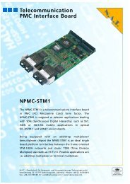
block diagram gives an overview about the main <strong>MCH</strong> building blocks.<br />
RJ45<br />
100 BaseT<br />
- Management -<br />
Fast Ethernet<br />
RJ45<br />
GigaBit Gigabit Uplink<br />
BNC on<br />
faceplate<br />
Indicator<br />
Leds<br />
Face Plate<br />
<strong>NAT</strong>-<strong>MCH</strong><br />
– Block Diagram -<br />
Local IPMI, SPI<br />
CPU<br />
Carrier Manager<br />
Shelf Manager (opt.)<br />
System Manager (opt)<br />
OS<br />
Mng Controller<br />
Stratum 3<br />
PLL<br />
Mng Controller<br />
Spread<br />
Spectrum<br />
PLL<br />
<strong>Version</strong> <strong>1.16</strong> © N.A.T. GmbH 13<br />
Local Bus<br />
MII<br />
Alternatives: 10GbE, SRIO<br />
GigEth<br />
Switch<br />
FPGA<br />
PCI Express<br />
Switch<br />
PCIe<br />
x8<br />
FPGA<br />
PCI Express<br />
Switch<br />
IPMI<br />
Fabric A<br />
Optional<br />
Clock 1-3<br />
Fabric B<br />
Clock-PCB - Optional<br />
AMC 1-6<br />
Fabric D-G<br />
AMC 7-12<br />
Fabric D-G<br />
HUB-PCB - Optional<br />
Backplane<br />
Tongue 1<br />
Tongue 2<br />
Tongue 3<br />
Tongue 4<br />
Figure 1 : <strong>NAT</strong>-<strong>MCH</strong> Block Diagram with PCIe Mezzanine Option shown
<strong>NAT</strong>-<strong>MCH</strong> – <strong>Users</strong> <strong>Manual</strong><br />
2.1 <strong>NAT</strong>-<strong>MCH</strong> Variants<br />
The following table lists the available variants and its features for the <strong>NAT</strong>-<strong>MCH</strong>:<br />
<strong>NAT</strong>-<strong>MCH</strong> LC<br />
(low cost)<br />
Gen2 Gen3<br />
Base Functionality: • • •<br />
Management of up to 12 AMCs 2<br />
CUs, 4 PMs<br />
• • •<br />
Onboard Shelf Manager • • •<br />
Console Port USB RS232 USB<br />
RMCP (GbE) based management<br />
interface<br />
• • •<br />
GbE Uplink Ports 1 1 2<br />
Port Trunking with second GbE<br />
Uplink Port<br />
•<br />
Power fail safe SDR Repository •<br />
Bicolour LEDs for status indication<br />
of AMCs, PMs and CUs<br />
• •<br />
Clock and Fat Pipe mezzanines • •<br />
Real Time Clock • •<br />
JTAG/JSM support •<br />
Faceplate: Full/Mid/<br />
Compact<br />
Full Full/Mid<br />
Clock Module Mezzanine: • •<br />
AMC clocks supported 1,2,3 F_CLK 1,2,3 F_CLK<br />
PLL Accuracy Stratum 3 Stratum 3 +<br />
Stratum 3E<br />
(Option)<br />
Face plate reference clock 1 (input) 2 (input/output)<br />
Clock Input Amplifier fixed modular<br />
Fabric Clock Support (PCIe) HCSL HCSL<br />
Spread Spectrum support (F_CLK) • •<br />
Fat Pipe Mezzanines • •<br />
Variants PCIe, XAUI, PCIe, XAUI,<br />
SRIO<br />
SRIO<br />
Uplink ports at face plate 2<br />
XAUI,SRIO<br />
PCIe Support Gen 1 Gen1, Gen2<br />
GbE Support Type 1,5,6 Type 1,5,6<br />
Management Software<br />
<strong>Version</strong> <strong>1.16</strong> © N.A.T. GmbH 14
<strong>NAT</strong>-<strong>MCH</strong> – <strong>Users</strong> <strong>Manual</strong><br />
External User Interface RMCP RMCP RMCP<br />
<strong>NAT</strong>view – Graphical User Interface • • •<br />
(open)HPI • • •<br />
IPMI Tool • • •<br />
Table 2: <strong>MCH</strong> Variants and Features<br />
<strong>Version</strong> <strong>1.16</strong> © N.A.T. GmbH 15
<strong>NAT</strong>-<strong>MCH</strong> – <strong>Users</strong> <strong>Manual</strong><br />
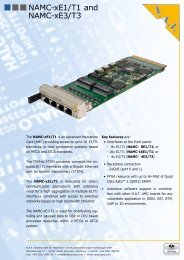
2.2 <strong>NAT</strong>-<strong>MCH</strong> Gen2: Connectors and Indicators at the Face Plate<br />
Ejector<br />
Handle<br />
Console Interface<br />
RS232, 19200,8,n,1<br />
AMC, PM, Cu Indicator<br />
Leds<br />
External Clock<br />
Input for Telecom<br />
Clocking Option<br />
100 BaseT<br />
Mangement Link<br />
Figure 2 : <strong>NAT</strong>-<strong>MCH</strong> Front Panel<br />
1000BaseT<br />
Farbric A uplink<br />
2.2.1 LED Indicators<br />
The <strong>NAT</strong>-<strong>MCH</strong> is equipped with two sets of indicators LEDs:<br />
• 4 indicator LEDs according to AMC.0 specification<br />
• 16 indicator LEDs displaying the status of AMC modules, Cooling Units and Power<br />
Modules<br />
The four AMC.0 conformant LEDs are assigned to the following functions:<br />
• Blue LED: Blue LED function according to AMC.0<br />
• Red LED: severe fault<br />
• Green LED: <strong>MCH</strong> has taken over role of primary <strong>MCH</strong><br />
• Yellow LED: <strong>MCH</strong> is redundant<br />
The 16 bi-color LEDs at the upper border of the <strong>MCH</strong> give an immediate visual feedback of<br />
the status of the corresponding module. Its functions are:<br />
• green: AMC, CU or PM module fully inserted and operational<br />
• green blinking – activation /de-activation under progress<br />
• red – module faulty or did not progress into operational state, communication fault<br />
<strong>Version</strong> <strong>1.16</strong> © N.A.T. GmbH 16<br />
Blue<br />
Led
<strong>NAT</strong>-<strong>MCH</strong> – <strong>Users</strong> <strong>Manual</strong><br />
2.2.2 SMA Connector – External Clock Reference<br />
This input can be used to provide the <strong>NAT</strong>-<strong>MCH</strong> with a system wide clock, which can be<br />
distributed by the Telecom Clocking Module to any AMC slot in the system. For technical<br />
data of this input please refer to the <strong>NAT</strong>-<strong>MCH</strong> Features section.<br />
2.2.3 100 BaseT interface – primary Management Interface Port<br />
The 100BaseT interface provides an autonegotiation 10/100 MBit link to the onboard CPU.<br />
This is the default management port and can be used by any external Shelf or System<br />
Manager to control the operation of the <strong>NAT</strong>-<strong>MCH</strong> and the system. The onboard CPU<br />
supports TCP/IP and RMCP accesses.<br />
Note: The management port can be switched to the GbE uplink port by a configuration option<br />
(see chapter Configuration below).<br />
2.2.4 GigaBit Ethernet (GbE) Uplink Port<br />
The GbE Uplink Port provides a direct access to the onboard GbE Switch fro Fabric A. Thus<br />
the Fabric connections can be extended to other shelfs or systems if required.<br />
Optionally the GbE Uplink Port can take over the management port functionality (see above).<br />
2.2.5 Console (Dbg) Port<br />
The console port provides an interface to the Command Line Interface (CLI) of the onboard<br />
CPU. The console interface can be used to set the operational and configuration parameters of<br />
the <strong>NAT</strong>-<strong>MCH</strong>. Once the IP configuration has been done, the console interface can be<br />
switched to a Telnet session.<br />
Important Note: The console port has changed from Gen2 <strong>MCH</strong> to Gen3 <strong>MCH</strong> from a<br />
RS232 type interface to an USB type interface. To prevent any mismatch the connector type<br />
has been changed too, so that a false connection can be excluded as far as possible.<br />
2.2.5.1 Console Port of <strong>MCH</strong> V1.x and V2.x (Gen1 and Gen2) – RS232<br />
The <strong>MCH</strong> of generation 1 and 2 have a RS232 based console port interface.<br />
The default parameters of the console port are: 19200,8,N,1<br />
The default baud rate can be changed within the <strong>MCH</strong> configuration settings (see Chap. 5).<br />
Important Note: Despite the connector type may indicate that the console port of the <strong>NAT</strong>-<br />
<strong>MCH</strong> is an USB port it is realized as a RS232 interface. Never connect this port to the USB<br />
port of a computer or to a hub. Unpredictable damage might be the result.<br />
<strong>Version</strong> <strong>1.16</strong> © N.A.T. GmbH 17
<strong>NAT</strong>-<strong>MCH</strong> – <strong>Users</strong> <strong>Manual</strong><br />
2.3 <strong>NAT</strong>-<strong>MCH</strong> Gen3: Connectors and Indicators at the Face Plate<br />
Primary/<br />
Secondary<br />
Indicator Led<br />
Fault Led<br />
GbE Uplink1<br />
- Management Port -<br />
Fat Pipe Uplinks<br />
Link Status<br />
GbE<br />
Uplink 2<br />
Reference Clock<br />
In/Out<br />
Fat Pipe<br />
Uplinks<br />
USB<br />
Console<br />
Extraction<br />
Handle<br />
FRU Status<br />
Leds<br />
2.3.1 LED Indicators<br />
The <strong>NAT</strong>-<strong>MCH</strong> is equipped with two sets of indicators LEDs:<br />
• 3 indicator LEDs according to AMC.0 specification<br />
• 16 indicator LEDs displaying the status of AMC modules, Cooling Units and Power<br />
Modules<br />
<strong>Version</strong> <strong>1.16</strong> © N.A.T. GmbH 18<br />
Blue Led<br />
The three AMC.0 conformant LEDs are assigned to the following functions:<br />
• Blue LED: Blue LED function according to AMC.0<br />
• Red LED: severe fault<br />
• Bicolor Led Green/Yellow:<br />
o Green: <strong>MCH</strong> is primary management controller<br />
o Yellow LED: <strong>MCH</strong> is redundant/standby<br />
The 16 bi-color LEDs give an immediate visual feedback of the status of the corresponding<br />
FRU device. Its functions are:<br />
• green: AMC, CU or PM module fully inserted and operational<br />
• green blinking – activation /de-activation under progress<br />
• red – module faulty or did not progress into operational state, communication fault
<strong>NAT</strong>-<strong>MCH</strong> – <strong>Users</strong> <strong>Manual</strong><br />
2.3.2 SMA Connectors – External Clock Reference<br />
This input/output can be used to feed an external reference clock into the <strong>NAT</strong>-<strong>MCH</strong> or<br />
provide a reference clock for other systems. The input clock can be distributed by the<br />
Telecom Clocking Module to any AMC slot in the system. The output can provide a clock<br />
sourced from any of the AMCs or a local clock generated by the onboard PLL.<br />
For technical data of this input/ouput please refer to the <strong>NAT</strong>-<strong>MCH</strong> Features section.<br />
2.3.3 Dual GbE Uplink Port<br />
The <strong>NAT</strong>-<strong>MCH</strong> has two 10/100/1000 BaseT (autonegotiation) uplink ports which are<br />
connected to the internal GbE switch circuit. The ports can be joined together in port trunking<br />
mode to double the uplink throughput performance. One of the ports is used as the designated<br />
management port.<br />
2.3.4 Management Interface Port<br />
One of the GbE uplink ports is used as the management interface fro external hosts to<br />
communicate with the onboard Shelf/Carrier manager by RMCP. By default the management<br />
port is assigned to GbE uplink port 1<br />
The management port can be used by any external Shelf or System Manager to control the<br />
operation of the <strong>NAT</strong>-<strong>MCH</strong> and the system. The onboard CPU supports TCP/IP and RMCP<br />
accesses.<br />
2.3.5 Console Port – USB / Telnet<br />
The console port provides an interface to the Command Line Interface (CLI) of the onboard<br />
CPU. The console interface can be used to set the operational and configuration parameters of<br />
the <strong>NAT</strong>-<strong>MCH</strong>. Once the IP configuration has been set, the console interface can be switched<br />
to a Telnet session by connecting via Telnet.<br />
2.3.5.1 Console Port of <strong>MCH</strong> V3.x (Gen3) - USB<br />
The <strong>NAT</strong>-<strong>MCH</strong> of generation 3 (V3.x) use a USB interface as console port. The console port<br />
provides a USB-CDC type of interface. Interoperability has been tested with the standard<br />
drivers included in Windows 2000,XP, Vista and Linux.<br />
When connecting first time to a windows machine a new device will be installed (<strong>NAT</strong>-<strong>MCH</strong><br />
console). To successfully complete the installation a device information file must be provided<br />
to the system. N.AT. provides the required “nat_mch.inf” text file for download from its web<br />
side or ftp server.<br />
Under Windows the new device can be accessed by standard terminal programs like<br />
“terraterm” (COMxx) port. The new device and the assigned COM port can be looked up in<br />
the Windows device manager.<br />
<strong>Version</strong> <strong>1.16</strong> © N.A.T. GmbH 19
<strong>NAT</strong>-<strong>MCH</strong> – <strong>Users</strong> <strong>Manual</strong><br />
Note: Do not start the terminal program before the USB link has been established, because the<br />
normal terminal programs need an activated link to connect to. To avoid the loss of log<br />
messages the <strong>MCH</strong> keeps a history buffer which can be recalled by the CLI command<br />
“history”.<br />
Under Linux the new device can be access via device desciptor “ttyXYZ” by standard<br />
terminal programs like “minicom”. The name of the newly generated device descriptor is<br />
system dependant and needs to be looked up in the devices directory.<br />
<strong>Version</strong> <strong>1.16</strong> © N.A.T. GmbH 20
<strong>NAT</strong>-<strong>MCH</strong> – <strong>Users</strong> <strong>Manual</strong><br />
2.4 <strong>NAT</strong>-<strong>MCH</strong>-LC: Connectors and Indicators at the Face Plate<br />
Primary/<br />
Secondary<br />
Indicator Led<br />
Fault Led<br />
GbE Uplink1<br />
- Management Port -<br />
USB<br />
Console<br />
Extraction<br />
Handle<br />
<strong>Version</strong> <strong>1.16</strong> © N.A.T. GmbH 21<br />
Blue Led<br />
2.4.1 LED Indicators<br />
The <strong>NAT</strong>-<strong>MCH</strong> is equipped with 3 indicator LEDs according to AMC.0 specification<br />
The three AMC.0 conformant LEDs are assigned to the following functions:<br />
• Blue LED: Blue LED function according to AMC.0<br />
• Red LED: severe fault<br />
• Bicolor Led Green/Yellow:<br />
o Green: <strong>MCH</strong> is primary management controller<br />
o Yellow LED: <strong>MCH</strong> is redundant/standby<br />
2.4.2 GbE Uplink Port<br />
The <strong>NAT</strong>-<strong>MCH</strong>-LC has one 10/100/1000 BaseT (autonegotiation) uplink port. The port is<br />
connected to the onboard GbE switch. This is the designated management interface, too.<br />
2.4.3 Management Interface Port<br />
The GbE uplink port is used as the management interface port fro external hosts to<br />
communicate with the onboard Shelf/Carrier manager by RMCP. The management port can<br />
be used by any external Shelf or System Manager to control the operation of the <strong>NAT</strong>-<strong>MCH</strong><br />
and the system. The onboard CPU supports TCP/IP and RMCP accesses.
<strong>NAT</strong>-<strong>MCH</strong> – <strong>Users</strong> <strong>Manual</strong><br />
2.4.4 Console Port – USB / Telnet<br />
The console port provides an interface to the Command Line Interface (CLI) of the onboard<br />
CPU. The console interface can be used to set the operational and configuration parameters of<br />
the <strong>NAT</strong>-<strong>MCH</strong>. Once the IP configuration has been set, the console interface can be switched<br />
to a Telnet session by connecting via Telnet..<br />
For a detailed description, please refer to chapter 2.3 above.<br />
<strong>Version</strong> <strong>1.16</strong> © N.A.T. GmbH 22
<strong>NAT</strong>-<strong>MCH</strong> – <strong>Users</strong> <strong>Manual</strong><br />
3 Mezzanine Module Options<br />
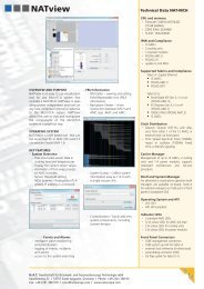
The <strong>NAT</strong>-<strong>MCH</strong> base board is a modular design and can be completed with additional<br />
functionalities by adding Mezzanine PCBs for the tongues 2-4.<br />
LED Module<br />
Base Module<br />
Hub Module<br />
PCIe – SRIO – 10GbE<br />
CLK Module<br />
Figure 3 : <strong>NAT</strong>-<strong>MCH</strong> Mezzanine Options<br />
3.1.1 Base Module<br />
The <strong>NAT</strong>-<strong>MCH</strong> Base Module carries the main CPU, the IPMI controllers for up to 12 AMC<br />
modules, Power and Cooling Units and backplane devices and the front panel connectors.<br />
The Base module is available in two assembly options:<br />
• Base 6 – for systems with up to 6 AMC modules<br />
• Base 12 – for systems with up to 12 AMC modules<br />
The Gen2 base module can optionally be equipped with a GbE Level 2 switch for Fabric A<br />
for up to 12 AMC modules, backplane backup link, and front panel uplink.<br />
• Option: -GbE<br />
The Gen3 base module is always equipped with the GbE Level 2 switch.<br />
Note: The GbE option is mandatory for redundant operation of the Gne2 <strong>MCH</strong>.<br />
<strong>Version</strong> <strong>1.16</strong> © N.A.T. GmbH 23
<strong>NAT</strong>-<strong>MCH</strong> – <strong>Users</strong> <strong>Manual</strong><br />
3.1.2 Clock Modules<br />
Available Options:<br />
• -TC: Telecom Clocking<br />
• -SSC: Spread Spectrum clocking for FCLK-A (only in combination with option –X24<br />
or –X48)<br />
3.1.2.1 Telecom Clocking Module<br />
The clock module provides the telecom clocks CLK1 and CLK2 to the 12 AMC modules as<br />
well as the fabric clock FCLK-A.<br />
The telecom clocks can be sourced from either of the AMC modules by means of CLK2 as an<br />
input to the <strong>MCH</strong> or from the front panel external clock reference input.<br />
3.1.2.2 Spread Spectrum Clocking Module (SSC)<br />
The Spread Spectrum Clocking module (SSC) distributes a 100 MHz clock to any of the<br />
AMC slots. The clock can be configured to be a standard 100 MHz clock or a 100MHz<br />
Spread Spectrum Clock (see Table 2). The clock is switched onto the individual AMC slots<br />
according to the E-Keying definitions acquired from the AMC module in the respective slot.<br />
3.1.3 HUB Mezzanine Modules<br />
Optionally the <strong>NAT</strong>-<strong>MCH</strong> can be equipped with mezzanine modules which provide the data<br />
switching functionalities for the fabrics D-G of the uTCA backplane.<br />
The available and planned options are:<br />
• -X24: PCIe Hub module for up to 6 AMC modules<br />
• -X48: PCIe Hub module for up to 12 AMC modules<br />
• -SRIO: Serial Rapid I/O module for up to 12 AMC modules<br />
• -XAUI: (10 GbE) module for up to 12 AMC modules<br />
For a detailed description of these modules and their technical data, please refer to the<br />
corresponding hardware manual.<br />
3.1.3.1 PCI Express Switching Module (X24 and X48)<br />
The PCIe module X24 (X48) supports switching of 1-4 PCIe lanes for up to 6 (12) AMC<br />
slots.<br />
Several configuration options which can be set by the <strong>MCH</strong> configuration menu (see Chapter<br />
Configuration) allow the flexible adoption of the PCIe hub to a certain environment.<br />
<strong>Version</strong> <strong>1.16</strong> © N.A.T. GmbH 24
<strong>NAT</strong>-<strong>MCH</strong> – <strong>Users</strong> <strong>Manual</strong><br />
3.1.3.2 SRIO Switching Module (x24 and x48)<br />
The SRIO module x24(x48) supports switching of 1 or 4 lanes SRIO for up to 6(12) AMC<br />
slots. The baud rate of each port can be selected independently between 1,25 Gbit/s, 2,5<br />
Gbit/s and 3,125Gbit/s.<br />
With the help of E-Keying the baud rate configured according the supported baud rate of the<br />
connected AMC.<br />
3.1.3.3 XAUI (10 Gigabit Ethernet) Switching Module (X24 and X48)<br />
The XAUI module X24 (X48) supports switching of 10 gigabit Ethernet for up to 6 (12)<br />
AMC slots and a 2 nd <strong>MCH</strong>.<br />
Additional the XAUI Module can be equipped with an optional face plate module (available<br />
in Q4 2008). With this module there are also two 10 gigabit Ethernet interfaces accessible at<br />
the face plate of the <strong>MCH</strong>.<br />
There are two versions of the face plate module available a CX4 and a SFP+ version. The<br />
CX4 version offers two CX4 interfaces (10 GbE over a copper cable). The SFP+ version<br />
offers two SFP+ cages. These cages can be assembled with any SFP+ transceiver. There are<br />
different SFP+ transceivers available, from different vendors for different optical interfaces.<br />
If a compliant AMC is recognized via E-Keying the dedicated port of the switch is<br />
automatically enabled by the firmware. Then the switch is in a forwarding state.<br />
<strong>Version</strong> <strong>1.16</strong> © N.A.T. GmbH 25
<strong>NAT</strong>-<strong>MCH</strong> – <strong>Users</strong> <strong>Manual</strong><br />
<strong>Version</strong> <strong>1.16</strong> © N.A.T. GmbH 26
<strong>NAT</strong>-<strong>MCH</strong> – <strong>Users</strong> <strong>Manual</strong><br />
4 Operation<br />
The <strong>NAT</strong>-<strong>MCH</strong> should be operated in a MTCA R1.0 compliant uTCA shelf with forced air<br />
cooling only. This manual describes the operation of the following <strong>NAT</strong>-<strong>MCH</strong> PCB versions<br />
and firmware releases:<br />
<strong>NAT</strong>-<strong>MCH</strong> V1.1 Firmware V2.1 and later<br />
<strong>NAT</strong>-<strong>MCH</strong> V2.0 Firmware V2.1 and later<br />
<strong>NAT</strong>-<strong>MCH</strong> V2.1 Firmware V2.1 and later<br />
4.1 System Startup and Redundancy Operation<br />
After power-up the <strong>NAT</strong>-<strong>MCH</strong> tries to read the backplane FRU information and locates the<br />
available power modules. The <strong>NAT</strong>-<strong>MCH</strong> determines the primary and the secondary power<br />
module according to the role of the power module. In parallel the <strong>MCH</strong> tries to locate a<br />
second <strong>MCH</strong> in the system and if one exists, it starts the negotiation process to assign primary<br />
and backup roles to the <strong>MCH</strong>s.<br />
If a second <strong>MCH</strong> is found in a redundant system, the primary <strong>MCH</strong> immediately starts<br />
backing up its internal database to the redundant <strong>MCH</strong> on a frequent basis via the GbE<br />
backplane link.<br />
To run the <strong>MCH</strong> in redundant configuration the GigaBit Ethernet option (-GbE) is mandatory.<br />
4.2 AMC Module Startup Sequencing<br />
After the <strong>NAT</strong>-<strong>MCH</strong> has completed its initial startup sequence it scans the system for<br />
available AMC modules. For any slot which is populated by an AMC module, a green LED<br />
on the face plate is lit. For all AMC modules found in the system, the <strong>MCH</strong> reads in the FRU<br />
information and sensor data records. If power negotiation is successful, it directs the power<br />
module to power up the AMC modules either in the activation sequence defined in the<br />
“Carrier Activation and Current descriptor“ record of the backplane FRU device –or- if the<br />
record is not found, according to the site number.<br />
4.3 Local Shelf Manager<br />
The local Shelf manager of the <strong>NAT</strong>-<strong>MCH</strong> provides management of the following resources<br />
within a uTCA system:<br />
• Sensor Event Log (SEL)<br />
• Temperature management and Cooling Unit control<br />
<strong>Version</strong> <strong>1.16</strong> © N.A.T. GmbH 27
<strong>NAT</strong>-<strong>MCH</strong> – <strong>Users</strong> <strong>Manual</strong><br />
4.3.1 Sensor Event Log<br />
The <strong>MCH</strong> provides a System Event Log (SEL) that stores all events that occur in a uTCA<br />
system. The stored events are kept in the <strong>MCH</strong>’s DRAM and are note stored into persistent<br />
memory.<br />
Events can be read by an application using the IPMI message GET_SEL_ENTRY_REQ. In<br />
the <strong>MCH</strong>’s default configuration events are removed from the SEL on read. Keeping events<br />
in the SEL after reading them can be configured using the <strong>MCH</strong> configuration menu (refer to<br />
chapter 5). To remove single events from the SEL in this configuration IPMI message<br />
DELETE_SEL_ENTRY_REQ has to be sent to the <strong>MCH</strong>, to clear the whole SEL IPMI<br />
message CLEAR_SEL_REQ has to be sent to the <strong>MCH</strong>.<br />
Please note that some events (e.g. temperature events) are handled by the local shelf manager<br />
(refer to chapter 4.3.2).<br />
4.3.2 Temperature Management<br />
The local shelf manager receives temperature events from following sources<br />
• Local temperature sensors on the <strong>MCH</strong><br />
• Temperature sensors on the AMC modules<br />
• Temperature sensors on Cooling Units and Power Modules<br />
In case the <strong>MCH</strong> receives a temperature event (temperature going high event) from a FRU,<br />
i.e. the temperature of a certain module has reached a critical level, it increases the fan speed<br />
of the cooling units to the maximum level and starts monitoring the temperature sensors of the<br />
respective FRU. As soon as the temperature returns to normal level the fan speed will be<br />
decreased to a level which is 10% higher than the level it was when the temperature event<br />
occurs. The initial normal fan level can be set in the <strong>MCH</strong> configuration menu by the value of<br />
the configuration parameter:<br />
Within the <strong>MCH</strong> global parameter section<br />
<br />
4.4 <strong>NAT</strong>-<strong>MCH</strong>s operating with unmanaged Power Modules<br />
The <strong>NAT</strong>-<strong>MCH</strong> is capable to manage systems which use so called “power through” modules.<br />
In this case the detection of modules is not done by the power modules (i.e. presence of #PS1<br />
signal), but the <strong>NAT</strong>-<strong>MCH</strong> itself starts scanning all AMC slots by IPMI messages. Of course,<br />
<strong>Version</strong> <strong>1.16</strong> © N.A.T. GmbH 28
<strong>NAT</strong>-<strong>MCH</strong> – <strong>Users</strong> <strong>Manual</strong><br />
due to the limited functionality of such a power module, functionalities like power sequencing<br />
and hot swap are not available.<br />
<strong>Version</strong> <strong>1.16</strong> © N.A.T. GmbH 29
<strong>NAT</strong>-<strong>MCH</strong> – <strong>Users</strong> <strong>Manual</strong><br />
5 <strong>MCH</strong> Configuration<br />
The operation of the <strong>NAT</strong>-<strong>MCH</strong> can be adapted to certain environments by configuration<br />
options. The basic idea behind the configuration options is that a customer usually has to<br />
touch as less parameters as possible. Therefore, in most cases the default configuration will<br />
work.<br />
The <strong>MCH</strong> configuration parameters are divided into several sections according to<br />
functionality:<br />
• Global parameter – contains configuration values for basic <strong>MCH</strong> operation<br />
• Shelf Manager parameter – configuration options for the local Shelf manager<br />
• Carrier Manager parameter – configuration options for the Carrier manager<br />
• SEL parameter – Sensor Event Log configuration<br />
• GbE switch parameter – configuration options for the onboard Fabric A GbE<br />
switch<br />
• CLK module parameter – configuration options for clock module (optional)<br />
• PCIe/SRIO parameter – configuration options for the PCIe/SRIO Hub<br />
module (optional)<br />
• NTP parameter - configuration options for optional Network Time Protocol<br />
support<br />
• DHCP parameter – configuration of the build in DHCP client<br />
5.1 Configuration via console port<br />
All configuration parameters are stored in the <strong>NAT</strong>-<strong>MCH</strong> configuration record in an onboard<br />
I2C EEProm. In order to change the configuration the <strong>MCH</strong>s console port needs to be<br />
connected to a Host computer.<br />
The <strong>NAT</strong>-<strong>MCH</strong> Gen2 provides the console port via a RS232 interface. Connect a VT100<br />
type terminal or a PC running a terminal program (e.g. TeraTerm, minicom etc.) to the<br />
console port (19200,8,N,1) by the supplied cable.<br />
The <strong>NAT</strong>-<strong>MCH</strong> Gen3 or –LC provides the console port via a standard USB connector. The<br />
<strong>MCH</strong> identifies itself as a CDC type device and is supported by the standard “usbser.sys”<br />
driver within Windows2000/XP/Vista. An appropriate configuration file can be downloaded<br />
from N.A.T.s web side or FTP server (file “nat_mch.inf”). After the connection has been<br />
recognized by the USB driver, a terminal program (e.g. TeraTerm, minicom etc.) can be used<br />
via the assigned virtual COM port.<br />
Press until you see the “nat>” prompt at the console.<br />
<strong>Version</strong> <strong>1.16</strong> © N.A.T. GmbH 30
<strong>NAT</strong>-<strong>MCH</strong> – <strong>Users</strong> <strong>Manual</strong><br />
The <strong>MCH</strong> is providing a low level command line interface (CLI) which allows to set certain<br />
operational parameters and to display run time information from the <strong>MCH</strong> and the system.<br />
Entering “?” will give you a list of available commands.<br />
For displaying and modifying the <strong>MCH</strong> configuration the following commands have been<br />
implemented:<br />
mch - prints all configuration settings<br />
mchcfg - menue based utility to set and modify configuration parameters<br />
ip - Basic Network configuration (IP addresses)<br />
Parameters which should keep their values can be acknowledged by simply hitting .<br />
For details about the <strong>MCH</strong> configuration please refer to chapter 5.4.<br />
Important Note: Despite the connector type may indicate that the console port of the <strong>NAT</strong>-<br />
<strong>MCH</strong> is an USB port, it is realized as a RS232 interface. Never connect this port to the USB<br />
port of a computer or to a hub. Unpredictable damage might be the result.<br />
5.2 Configuration via the WEB Interface<br />
All configuration parameters are accessible via the WEB interface as well. Please refer to<br />
Chapter 9 for the usage of the WEB interface. It can be necessary to setup a basic<br />
configuration like the IP address of the <strong>MCH</strong> before the WEB interface can be used.<br />
5.3 Customizing the Network Configuration<br />
The <strong>MCH</strong> requires IP address parameter to be adapted to make it working in your company’s<br />
network environment.<br />
Entering at the command line will show the actual configuration and allows you to<br />
change these parameters by line editing the displayed values. IP address parameters must be<br />
entered in “dot” notation. If an IP address is configured to 0.0.0.0 it will be ignored by the<br />
<strong>MCH</strong>, if you configure a non-zero gateway IP address the related routing configuration will<br />
be performed automatically when the <strong>MCH</strong> starts up.<br />
After all changes are done you will be asked to confirm the new configuration. If the new<br />
values shall be written into the I2C EEPROM, you should answer the question with and<br />
the new values will be become effective after the next power cycle.<br />
Please also refer to Appendix B for more information about the IP address configuration.<br />
5.4 Displaying and changing <strong>MCH</strong> operational parameters<br />
Entering at the command line will show you a list of operational parameters which<br />
allow you to adapt the <strong>MCH</strong> to certain environments and configurations.<br />
With the command it is possible to change these parameters.<br />
<strong>Version</strong> <strong>1.16</strong> © N.A.T. GmbH 31
<strong>NAT</strong>-<strong>MCH</strong> – <strong>Users</strong> <strong>Manual</strong><br />
The command will lead you to a menu driven utility which will allows you to<br />
modify the parameters within the individual sections according to their functionality.<br />
Currently the configuration menu contains the following entries:<br />
[ 0] no action<br />
[ 1] print complete configuration<br />
[ 2] reset to defaults<br />
[ 3] modify <strong>MCH</strong> global configuration<br />
[ 4] modify ShM configuration<br />
[ 5] modify CM configuration<br />
[ 6] modify SEL configuration<br />
[ 7] modify GbE switch configuration<br />
[ 8] modify PCIe/SRIO configuration (optional)<br />
[ 9] modify CLK module configuration (optional)<br />
[10] modify NTP configuration<br />
[11] modify DHCP configuration<br />
[ ?] print menu<br />
[ h] print menu<br />
[ q] quit and save configuration<br />
Entering the respective number will guide you to the associated configuration menu. [2] reset<br />
to defaults will reset all configuration parameters to a well known “healthy” setup.<br />
The following sections will describe the individual configuration options in detail.<br />
5.4.1 <strong>MCH</strong> Global Parameters [3]<br />
The <strong>MCH</strong> global parameter section contains basic operational and interface settings:<br />
Configuration Option default Description<br />
Management interface at GbE port disabled Allows re-routing of the management interface for<br />
RMCP and telnet access to the GbE Uplink port on the<br />
face plate. Default is using the 100BaseT port. (*)<br />
RMCP access enabled Allows to setup RMCP connections via the<br />
management port. Required for tools like openHPI,<br />
ipmiTool, NatView<br />
Telnet access enabled Allows remote login to the <strong>MCH</strong> via telenet<br />
WEB access enabled Allows access to the <strong>MCH</strong> from any browser<br />
IP address source Mgmt board<br />
configuration<br />
Source of the <strong>MCH</strong>s own IP address on the<br />
management port.<br />
Valid options are:<br />
• board configuration –saved value from local<br />
EEPROM – see chap. 5.3<br />
• DHCP<br />
• ShM Link record – IP address is taken from<br />
Carrier FRU device, Shelf FRU info record<br />
• CM IP link record – IP address is taken from<br />
Carrier FRU device, Carrier FRU info record<br />
<strong>Version</strong> <strong>1.16</strong> © N.A.T. GmbH 32
<strong>NAT</strong>-<strong>MCH</strong> – <strong>Users</strong> <strong>Manual</strong><br />
IP address source GbE board<br />
(**)<br />
Source of the <strong>MCH</strong>s own IP address on the Gigabit<br />
configuration Ethernet port.<br />
Valid options are:<br />
• board configuration –saved value from local<br />
EEPROM – see chap. 5.3<br />
• DHCP<br />
• ShM Link record – IP address is taken from<br />
Carrier FRU device, Shelf FRU info record<br />
•<br />
(**)<br />
CM IP link record – IP address is taken from<br />
Carrier FRU device, Carrier FRU info record<br />
RMCP session activity timeout 0 min Timeout for remote RMCP sessions being inactive –<br />
minutes<br />
minutes<br />
RMCP session activity timeout 60 sec Timeout for remote RMCP sessions being inactive –<br />
seconds<br />
seconds<br />
Default Fan Level 30% Default fan level in percent after power up.<br />
A value of 0 remains the default value of the cooling<br />
unit active.<br />
Enable backward compatibility No Enables backward compatibility to firmware version<br />
less or equal V2.4. If this mode is enabled CM and<br />
ShM behave as to use common SDR repository and<br />
SEL and single bridged IPMI messages are directly<br />
delivered to the target devices (PMs, CUs, AMCs,<br />
Clock/HUB modules). If this mode is disabled single<br />
bridged IPMI messages are delivered to the CM and<br />
target devices have to be accessed using double<br />
bridged IPMI messages which will be extracted first<br />
by the ShM and then by the CM.<br />
Remark (*)<br />
An external Shelf or System Manager can be connected to the <strong>NAT</strong>-<strong>MCH</strong> by an Ethernet connection running the<br />
RMCP protocol.<br />
By default the management port is routed to the front panel 100 BaseT port.<br />
Alternatively the management port can be switched to one link of the onboard GbE Switch. If the management<br />
port resides on the GbE switch, it can either be connected to an external shelf- or system manager by the GbE<br />
uplink port, or to any shelf or system controller running on one of the AMC modules, connected to the <strong>MCH</strong> by<br />
a GbE backplane link.<br />
Remark (**)<br />
Although it is possible to configure both the management and the gigabit Ethernet ports to obtain its IP<br />
configuration from DHCP it does not make sense because both Ethernet interfaces then will be located in the<br />
same subnet and it is not clear to which physical interface packets are routed. Such a configuration will lead to<br />
discarding of packets.<br />
Also note that DHCP is only allowed for the Ethernet port that is used for the management interface (refer to the<br />
option ‘Management interface at GbE port’). This means if the option ‘Management interface at GbE port’ is set<br />
to disabled DHCP can only be used for the ‘IP address source Mgmt’, if the option is enabled DHCP can only be<br />
used for the ‘IP address source GbE’.<br />
<strong>Version</strong> <strong>1.16</strong> © N.A.T. GmbH 33
<strong>NAT</strong>-<strong>MCH</strong> – <strong>Users</strong> <strong>Manual</strong><br />
5.4.2 Shelf Manager Configuration [4]<br />
The following configuration parameters control the operation of the local shelf manager<br />
onboard of the <strong>MCH</strong>.<br />
Configuration Option default Description<br />
Allow Shelf FRU invalid Yes Allows startup and operation of the <strong>MCH</strong> even though<br />
no valid Shelf FRU record is found on the backplane<br />
I2C device.<br />
Temperature management Enabled Allows the local Shelf manager to adapt the fan speed<br />
based on temperature events from the AMCs<br />
Emergency shutdown on critical disabled Shelf manager shuts down an AMC if a threshold<br />
event<br />
based sensor reaches the critical limit<br />
Emergency shutdown on non disabled Shelf manager shuts down an AMC if a threshold<br />
recoverable event<br />
based sensor reaches the non recoverable limit<br />
Use external Shelf Manager no Allows an external Shelf manager to operate via the<br />
RMCP interface. If enabled, the local shelf manager is<br />
suspended. Please note that usage of an external Shelf<br />
Manager is not yet supported.<br />
5.4.3 Carrier Manager Configuration [5]<br />
The carrier manager controls the communication and operation of the AMCs, power modules<br />
and cooling units.<br />
Configuration Option default Description<br />
Carrier number default 0 Allows the setting of a Carrier Number. If the value is<br />
0 the Carrier number is loaded from the Carrier FRU<br />
device or from backplane I/O Expander. (*)<br />
Quiesced event timeout 10 Timeout in seconds the <strong>MCH</strong> waits for a quiesce event<br />
from a FRU device in response of IPMI FRU<br />
CONTROL message “Quiesced” (**).<br />
The value of 255 defines an infinite timeout<br />
Allow carrier FRU invalid Yes Allows the <strong>MCH</strong> to operate with internal default<br />
values if no valid backplane FRU device is found.<br />
If the flag is not set and the backplane FRU contents is<br />
found invalid, the carrier manager will not enter<br />
normal operation mode.<br />
Overrule carrier FRU No Overrules the backplane FRU device and uses internal<br />
defaults<br />
Debugging Flags 0 Allows debugging or analyzing of certain areas of a<br />
uTCA system. (***)<br />
Remark (*)<br />
According to the uTCA specification the Carrier Number is defined either in the backplane FRU device or by<br />
DIP switches which can be read from an I/O expander at the I2C address 0x3e of the backplane IC2 bus.<br />
<strong>NAT</strong> has added a third option which can overrule the previous two by setting the carrier number in the <strong>MCH</strong><br />
configuration record.<br />
<strong>Version</strong> <strong>1.16</strong> © N.A.T. GmbH 34
<strong>NAT</strong>-<strong>MCH</strong> – <strong>Users</strong> <strong>Manual</strong><br />
Remark (**)<br />
If the handle of an AMC module is opened, the <strong>NAT</strong>-<strong>MCH</strong> transitions the module into state M6 and waits for<br />
the “Quiesced” event message. As modern CPUs and operating systems may take up to minutes to shutdown<br />
completely, a configurable timeout has been added, which defines how long the <strong>MCH</strong> will wail for the<br />
“Quiesced” event message before it turns.<br />
Remark(***)<br />
If a management problem in a uTCA system occurs it might be extremely helpful to switch on certain debug<br />
options to identify the cause fro the problem. Therefore the <strong>NAT</strong>-<strong>MCH</strong> allows setting debug levels for specific<br />
areas, like E-Keying, Cooling Unit management, etc.<br />
Note: In a complex system it is easy to overload the system by debugs, especially if several debug options are<br />
turned on at the same time. As the display is flooded with message in this case it might become difficult to turn<br />
off the debugs again as access to the CLI is limited.<br />
In such a case the system should be power cycled and the bootstrap process should be aborted by typing “z”<br />
immediately after the system has come up. This allows modifying the configuration parameters without<br />
disturbance from any debug output.<br />
5.4.4 SEL Configuration Flags [6]<br />
The SEL flags configure the behavior of the Sensor Event Log (SEL).<br />
Configuration Option default Description<br />
Keep on Read Disabled If enabled, SEL entries are not deleted upon read<br />
5.4.5 GbE Switch Configuration [7]<br />
The GbE Switch Configuration is used to configure the Ethernet switch located on the base<br />
board of the <strong>NAT</strong>-<strong>MCH</strong>. The different configuration options of the GbE switch are described<br />
in a separate manual (refer to Ethernet Switch Configuration <strong>Manual</strong>).<br />
Configuration Option default Description<br />
GbE configuration source none Specifies the source for the GbE switch configuration.<br />
• no configuration<br />
• load from FLASH<br />
5.4.6 CLK Module Configuration [8] (optional)<br />
The following options are used to configure the CLK module optionally mounted on the<br />
<strong>NAT</strong>-<strong>MCH</strong>. The clock module can be configured via a text based configuration file. For more<br />
information please refer to chapter 10.<br />
Configuration Option default Description<br />
CLK module configuration source none Specifies the source for the CLK module configuration.*<br />
• no configuration<br />
• load from FLASH<br />
<strong>Version</strong> <strong>1.16</strong> © N.A.T. GmbH 35
<strong>NAT</strong>-<strong>MCH</strong> – <strong>Users</strong> <strong>Manual</strong><br />
5.4.7 PCIe Switch Configuration [9] (optional)<br />
By the PCIe configuration parameters the operation of the (optional) PCIe Hub module is<br />
controlled.<br />
Configuration Option default Description<br />
operating mode (cluster 1) transparent Operation mode of the PCIe Switches (PCIe cluster<br />
1)*:<br />
• default (transparent)<br />
• NT Intelligent Adapter mode<br />
• NT Dual-Host mode<br />
Upstream transparent slot number 0 AMC slot number where the host CPU resides in. (i.e.<br />
(cluster 1)<br />
root complex). (PCIe cluster 1)*<br />
Upstream non-transp slot number 0 AMC slot number where the non transparent host<br />
(cluster 1)<br />
CPU resides in for dual host mode. (PCIe cluster 1)*<br />
operating mode (cluster 2) transparent Operation mode of the PCIe Switches (PCIe cluster<br />
2)*:<br />
• default (transparent)<br />
• NT Intelligent Adapter mode<br />
• NT Dual-Host mode<br />
Upstream transparent slot number 0 AMC slot number where the host CPU resides in. (i.e.<br />
(cluster 2)<br />
root complex). (PCIe cluster 2)*<br />
Upstream non-transparent slot 0 AMC slot number where the non transparent host<br />
number (cluster 2)<br />
CPU resides in for dual host mode. (PCIe cluster 2)*<br />
upstream slot power up delay 5 sec Delay applied to the slot where the upstream CPU<br />
resides in. The delay is applied before payload power<br />
is turned on. (*)<br />
100 MHz spread spectrum clock Disabled If enabled the FCLK-A clock will be of spread<br />
spectrum type with 100 MHz means. If disabled the<br />
FCLK-A is a 100MHz fixed clock.<br />
Hot plug support Disabled Enables PCIe Hot Plug Support.<br />
PCIe early Ekey Disabled Executes the E-Keying before Payload power is<br />
applied<br />
‘no ekey’ for PCIe Disabled Disables E-Keying for PCIe lanes (for debugging<br />
only)<br />
PCIe clustering Disabled Enables PCIe clustering for PCIe x48 HUB modules.<br />
If PCIe clustering is enabled the mode, transparent<br />
upstream and non-transparent upstream port<br />
parameters can be set for each switch separately. In<br />
communication between the two clusters is not<br />
possible in this case!<br />
Remarks (*)<br />
The power-up sequence and delays defined by the backplane FRU info device might not be sufficient in all<br />
situations for systems with PCIe boards, as usually all I/O boards need to be ready before the CPU board may<br />
start its PCI scan.<br />
Therefore an extra delay in the <strong>MCH</strong> configuration record can be defined for the PCIe upstream host.<br />
The settings for the second PCIe cluster are only valid if “PCIe clustering” is enabled via the corresponding flag.<br />
<strong>Version</strong> <strong>1.16</strong> © N.A.T. GmbH 36
<strong>NAT</strong>-<strong>MCH</strong> – <strong>Users</strong> <strong>Manual</strong><br />
5.4.8 SRIO Switch Configuration [9] (optional)<br />
By the SRIO configuration parameters the operation of the (optional) SRIO Hub module is<br />
controlled.<br />
Configuration Option default Description<br />
operating mode No uplink Operation mode of the SRIO Switches:<br />
• No uplink, dual x4 Interconnect (default)<br />
• Dual Uplink Mode<br />
• Single Uplink + BP Fabric Update<br />
5.4.9 NTP Configuration [10]<br />
Enables and configures the NTP client of the <strong>MCH</strong><br />
Configuration Option default Description<br />
NTP server IP 0.0.0.0 IP address of the NTP server<br />
NTP ‘check for time’ delay 0 Time interval to request an time update form the time<br />
minutes<br />
server<br />
NTP ‘check for time’ delay hours 0<br />
NTP local time offset 0 Local time offset to GMT in hours<br />
NTP client disabled Enables/disables NTP client<br />
5.4.10 DHCP Configuration [11]<br />
Allows setting of configuration options for the build in DCHP client.<br />
Note: The DHCP client is activated by setting the configuration option <br />
to “DCHP” in the global <strong>MCH</strong> parameters.<br />
Configuration Option default Description<br />
Hostname “” Designated Hostname for this <strong>MCH</strong><br />
Flags 0 - unused -<br />
<strong>Version</strong> <strong>1.16</strong> © N.A.T. GmbH 37
<strong>NAT</strong>-<strong>MCH</strong> – <strong>Users</strong> <strong>Manual</strong><br />
6 Updating the <strong>MCH</strong> firmware<br />
Firmware updates are supplied to customers as a result of bug fixes or enhancements<br />
implemented by N.A.T..<br />
To execute a firmware update the binary image supplied by N.A.T. must be available on a<br />
TFTP server within the customer’s network. The <strong>MCH</strong> must be connected to this network via<br />
the management Ethernet port. A terminal must be connected to the console port.<br />
6.1 Firmware Update from within the running <strong>MCH</strong> firmware<br />
The firmware can be updated while the normal <strong>MCH</strong> firmware is running. Real time behavior<br />
of the <strong>MCH</strong> may be slowed down during Flash update. To perform the update continue as<br />
described below “firmware update”.<br />
6.2 Firmware Update from Bootloader<br />
In cases were the <strong>MCH</strong> firmware image is corrupted due to aborted update process or similar,<br />
the firmware can be updated from with the bootloader.<br />
To initiate a firmware update the normal bootstrapping process of the <strong>MCH</strong> must be stopped.<br />
The <strong>MCH</strong> bootstrap process is executed in two phases: after power up an initial bootstrap<br />
loader is started which than starts the final <strong>MCH</strong> application firmware image. The initial<br />
bootloader can be kept off from entering the second phase by typing ‘x’ on the console<br />
terminal during the initial bootstrap phase. When the bootloader is stopped you are in the<br />
command line mode of the bootloader.<br />
6.3 Firmware Update<br />
To run the firmware update enter at the command line prompt. You will<br />
be asked for the path information of the new image in the form:<br />
<br />
where as has to be given in the “dot” notation.<br />
If the given information is correct, the new firmware image will be loaded and stored into the<br />
onboard Flash device.<br />
Warning: Do not power cycle the system during this process!<br />
When programming was successful, power cycle the system to boot the new firmware.<br />
<strong>Version</strong> <strong>1.16</strong> © N.A.T. GmbH 38
<strong>NAT</strong>-<strong>MCH</strong> – <strong>Users</strong> <strong>Manual</strong><br />
Problem tracking: In most cases when the TFTP download does not work, file protections<br />
on the TFTP server are not set correctly or firewalls prevent the <strong>MCH</strong> from downloading the<br />
image. If you encounter such a problem, please start investigations in these areas.<br />
<strong>Version</strong> <strong>1.16</strong> © N.A.T. GmbH 39
<strong>NAT</strong>-<strong>MCH</strong> – <strong>Users</strong> <strong>Manual</strong><br />
7 Management Interface<br />
For interfacing to an external shelf or system controller the <strong>NAT</strong>-<strong>MCH</strong> is equipped with a<br />
Ethernet based management port. The management port can either reside on the front panel<br />
100 BaseT port or on the GbE Uplink port. An external shelf or system controller can<br />
communicate with the <strong>MCH</strong> by the exchange of IPMI messages. The IPMI messages are<br />
encapsulated in RMCP packets for transport via the Ethernet. By this standard interface the<br />
user has access to a broad range of open source and commercial tools to access and manage<br />
the <strong>MCH</strong>.<br />
The N.A.T. graphical system management JAVA application “N.A.T. NatView” utilizes this<br />
interface as well.<br />
7.1 Software structure<br />
The following figure gives a basic overview about software structure on the <strong>MCH</strong>.<br />
Figure 4 : Software structure overview<br />
<strong>Version</strong> <strong>1.16</strong> © N.A.T. GmbH 40
<strong>NAT</strong>-<strong>MCH</strong> – <strong>Users</strong> <strong>Manual</strong><br />
The System management software (SMS) is running on a host system that communicates via<br />
the Remote management control protocol (RMCP) over Ethernet with the <strong>MCH</strong>. The <strong>MCH</strong><br />
itself implements base management controller (BMC) functionality and communicates via<br />
IPMI messages over I2C with hardware modules (e.g. Cooling Units, Power Modules, AMC<br />
cards) that run hardware module specific software.<br />
The next figure gives an example for a software implementation that uses a graphical JAVA<br />
application running on top of the OpenHPI (see 7.3.3) middleware on the host system:<br />
Figure 5 : Software structure details<br />
The system management software is described more detailed in the following chapters.<br />
The software on the <strong>MCH</strong> can be divided up into two parts: first a layer structured stack that<br />
implements the interfaces to external systems (host and hardware) and the message handling,<br />
and second helper modules to save data (IPMI data base, FRU inventory, SDR repository,<br />
SEL) and communication information (session management). Shelf Manager capability is<br />
optional and can be configured (see 5.4) to allow usage of an external shelf manager, e.g. on a<br />
<strong>Version</strong> <strong>1.16</strong> © N.A.T. GmbH 41
<strong>NAT</strong>-<strong>MCH</strong> – <strong>Users</strong> <strong>Manual</strong><br />
host system or an AMC module. Note that the SEL on the <strong>MCH</strong> is kept in memory but not<br />
stored into persistent memory.<br />
7.2 Communication between host system and <strong>MCH</strong><br />
Communication between a host system and the <strong>MCH</strong> is done via IPMI messages. To allow a<br />
flexible and common available transport of these IPMI messages the <strong>MCH</strong> offers an Ethernet<br />
based management interface.<br />
7.2.1 Remote management control protocol<br />
Transport over Ethernet usually requires some high level protocols to be used. The <strong>MCH</strong><br />
implements a ‘Remote Management Control Protocol’ (RMCP, defined by the Distributed<br />
Management Task Force (DMTF, http://www.dmtf.org/) interface whereby the IPMI<br />
messages are embedded into the RMCP messages that are sent using UDP over an Ethernet<br />
channel.<br />
The RMCP fulfills all requirements that are necessary to transfer IPMI messages over the<br />
Ethernet:<br />
• Presence echo mechanism (RMPC ping/pong messages)<br />
• Message flow control via sequence numbers<br />
• Support for multi-session<br />
• Transfer of session header<br />
• Support for authenticated access<br />
• Per-message authentification disable<br />
• User-level authentification disable<br />
The <strong>MCH</strong> supports access to the RMPC interface via its front Ethernet management interface<br />
(refer to 1.1.6). Since <strong>MCH</strong> firmware version 2.0 the <strong>MCH</strong> supports access to the RMCP<br />
interface via its backplane Ethernet interface. Selection between these two interfaces can be<br />
configured (refer to chapter 5.4).<br />
7.2.2 Supported IPMI messages<br />
Handling of IPMI messages is done within a separate module of the software. The message<br />
module’s configuration and a list of supported messages can be obtained using the CLI<br />
command ‘imsg_info’ (refer to chapter 8). This command allows printing the compile time<br />
configuration (list of supported message modules), the run time configuration and a list of<br />
request messages that are supported.<br />
7.3 Host software overview<br />
7.3.1 N.A.T. JAVA GUI application ‘NatView’<br />
<strong>Version</strong> <strong>1.16</strong> © N.A.T. GmbH 42
<strong>NAT</strong>-<strong>MCH</strong> – <strong>Users</strong> <strong>Manual</strong><br />
NatView is a graphical application that can be used to monitor and control a MTCA system<br />
using IPMI messages. The application is written entirely in Java – it should therefore run on<br />
every operating system that is able to execute the Sun Java Runtime Environment (JRE).<br />
7.3.1.1 Supported Java Releases<br />
NatView requires Sun Java 1.5 Update 14 or higher. We chose to use this Sun Java version to<br />
guarantee the largest possible JRE installation basis on Window, Linux and Mac OS X<br />
systems. If in doubt enter<br />
java –version<br />
in a command prompt window. An appropriate copy of the Sun JRE can be obtained at<br />
java.sun.com.<br />
7.3.1.2 Installing and running NatView<br />
NatView is usually distributed as a zip archive. Do the following steps to install NatView on<br />
your system:<br />
1. Extract the content of the zip archives to an empty directory. This empty directory will be<br />
the root directory of the application.<br />
2. Start the application from within the root directory. (Otherwise the application cannot<br />
find the board images in the subdirectory images.)<br />
From the command line type<br />
cd <br />
java –jar natview.jar<br />
7.3.1.3 Displaying new AMC boards<br />
The images of the detected AMC boards are not hardcoded into NatView. They reside in the<br />
subdirectory images below the application root directory. For every supported AMC board<br />
NatView expects two JPEG images, one for vertical aligned boards, and one for horizontal<br />
aligned ones. See the following table for details:<br />
Alignment Filename Width Height Format<br />
Horizontal l_.jpg (see Note) 110 42 JPG<br />
Vertical p_
<strong>NAT</strong>-<strong>MCH</strong> – <strong>Users</strong> <strong>Manual</strong><br />
Example:<br />
To display the N.A.T. <strong>MCH</strong> the image files 6c780b03l_nat_mch_full.jpg<br />
and 6c780b03l_nat_mch_full.jpg are necessary.<br />
7.3.1.4 Connecting to a MTCA chassis<br />
To monitor and control a MTCA system the NatView application needs to connect to the<br />
system <strong>MCH</strong>. To do this use the command Application->Connect. The following dialog<br />
window will appear:<br />
Figure 6 : NatView: Connecting to a MCTA chassis<br />
Enter the IP address of the system <strong>MCH</strong> and click on Connect. NatView will start to scan the<br />
system resources. The scan time depends on the number of AMC boards attached to the<br />
system.<br />
<strong>Version</strong> <strong>1.16</strong> © N.A.T. GmbH 44
<strong>NAT</strong>-<strong>MCH</strong> – <strong>Users</strong> <strong>Manual</strong><br />
After the scan has finished the detected resources are displayed in the application main<br />
window:<br />
Figure 7 : NatView: Main window<br />
7.3.2 Ipmitool<br />
Ipmitool (available at http://ipmitool.sourceforge.net/) is an open source utility that runs on a<br />
Linux PC for managing and configuring devices that support the Intelligent Platform<br />
Management Interface. IPMI is an open standard for monitoring, logging, recovery,<br />
inventory, and control of hardware that is implemented independent of the main CPU, BIOS,<br />
and OS. The service processor (or Baseboard Management Controller, BMC) is the brain<br />
behind platform management and its primary purpose is to handle the autonomous sensor<br />
monitoring and event logging features.<br />
<strong>Version</strong> <strong>1.16</strong> © N.A.T. GmbH 45
<strong>NAT</strong>-<strong>MCH</strong> – <strong>Users</strong> <strong>Manual</strong><br />
The ipmitool program provides a simple command-line interface to this BMC. It features the<br />
ability to read the sensor data repository (SDR) and print sensor values, display the contents<br />
of the System Event Log (SEL), print Field Replaceable Unit (FRU) inventory information,<br />
read and set LAN configuration parameters, and perform remote chassis power control.<br />
Ipmitool was not written to provide large-scale management application functionality. The<br />
functionality that ipmitool esource is easily accomplished by sending simple IPMI request<br />
messages and parsing the returned response. It is intended to be used by system administrators<br />
who like the simplicity and scriptability of command-line utilities, as well as those debugging<br />
or developing their own BMC implementations.<br />
Please note that ipmitool is still under development. N.A.T. recommends to use at least<br />
version 1.8.11 since this version fixes some already known bugs (e.g. wrong decoding of<br />
SEND_MESSAGE responses).<br />
7.3.2.1 ipmitool call syntax<br />
The following list gives examples for ipmitool call syntax:<br />
Common syntax to access the N.A.T. <strong>MCH</strong> over RMCP:<br />
� ipmitool –H -P “” <br />
Common syntax to access a target device behind the N.A.T. <strong>MCH</strong>:<br />
� ipmitool –H -P “” –t <br />
Common syntax to access a target device behind the N.A.T. <strong>MCH</strong> using ‘double bridged’<br />
OEM messages:<br />
� ipmitool –H -P “” –t -T <br />
raw <br />
where nfn is the network function code, cmd the IPMI message command and data the IPMI<br />
message data part given as hexadecimal values.<br />
7.3.3 OpenHPI<br />
This chapter gives a brief overview on how to install and start the OpenHPI for<br />
communication to the N.A.T. <strong>MCH</strong>. Please note that due to the availability of the JAVA base<br />
Natview tool N.A.T. support for making OpenHPI interworking with the N.A.T. <strong>MCH</strong> is<br />
obsolete now. However, N.A.T. continues performing tests using different OpenHPI versions.<br />
OpenHPI is an open source project created with the intent of providing an implementation of<br />
the Service Availability Forum’s Hardware Platform Interface (HPI,<br />
http://www.saforum.org/). HPI provides a universal interface for creating resource system<br />
<strong>Version</strong> <strong>1.16</strong> © N.A.T. GmbH 46
<strong>NAT</strong>-<strong>MCH</strong> – <strong>Users</strong> <strong>Manual</strong><br />
models, typically for chassis and rack based servers, but extendable for other problem<br />
domains such as clustering, virtualization and simulation.<br />
The current version of OpenHPI can be downloaded from http://www.openhpi.org/,<br />
documentation is available on http://openhpi.sourceforge.net/manual/book1.html. Please note<br />
that it is highly recommended to use the newest OpenHPI version that is available (currently<br />
2.14.0 in April 2009).<br />
7.3.3.1 Overview OpenHPI<br />
OpenHPI is used by N.A.T. as middleware to allow communication between the N.A.T.<br />
JAVA GUI HPI application and the N.A.T. <strong>MCH</strong>. Of course it is also possible to run other<br />
applications on top of OpenHPI.<br />
OpenHPI runs on a standard Linux PC. N.A.T. tested the current OpenHPI version on Debian<br />
3.1 (http://www.debian.org/), kernel 2.4.27 and on Debian 4.0, kernel 2.6.24 but it is known<br />
to run on other Linux distributions and other kernels as well. Once you have setup a Linux PC<br />
change into your preferred download directory and copy all distributed files into this<br />
directory:<br />
� cd <br />
� cp .<br />
Extract the provided OpenHPI tarball:<br />
� tar –xzvf openhpi-2.7.3.tar.gz<br />
and use the standard Linux mechanisms:<br />
� cd openhpi-2.7.3<br />
� ./configure && make && make install<br />
to install the software.<br />
The following sections give some more detailed information on how to configure, compile<br />
and install OpenHPI. For more information about OpenHPI please refer to the README files<br />
that come with the OpenHPI package.<br />
7.3.3.2 Configuring OpenHPI<br />
By default simply calling ‘./configure’ will build all plugins that can be built, all other<br />
plugins will be silently disabled. If you wish to disable a plugin, any flags you pass to<br />
configure will be passed to the ‘configure’ program.<br />
<strong>Version</strong> <strong>1.16</strong> © N.A.T. GmbH 47
<strong>NAT</strong>-<strong>MCH</strong> – <strong>Users</strong> <strong>Manual</strong><br />
For communication between OpenHPI and the <strong>NAT</strong>-<strong>MCH</strong> at least the plugin ‘ipmidirect’<br />
must be enabled (this is the default in OpenHPI 2.7.3).<br />
Please try<br />
� ./configure –help<br />
for more information on the options. Further configuration information can be obtained from<br />
the README file provided in the openhpi-2.7.3 package.<br />
7.3.3.3 Compiling OpenHPI<br />
OpenHPI can be compiled by calling ‘make’.<br />
The official release of OpenHPI 2.7.3 contains a bug (that is fixed since 2.8.x versions):<br />
./src/event.c:156: warning: `error’ might be used uninitialized<br />
this has to be fixed by replacing<br />
int error;<br />
by<br />
int error = SA_OK;<br />
in the file ‘./src/event.c’.<br />
7.3.3.4 Installing OpenHPI<br />
OpenHPI is installed by calling ‘make install’.<br />
Note that there is no daemon configuration file installed by default, so one has to copy it<br />
manually:<br />
� cp ./openhpi.conf.example /usr/local/etc/openhpi/openhpi.conf<br />
Alternatively the provided configuration file openhpi_nat.conf can be used for configuration:<br />
� cp ../examples/openhpi_nat.conf<br />
/usr/local/etc/openhpi/openhpi.conf<br />
7.3.3.5 Running OpenHPI<br />
Before the OpenHPI daemon is started please start up your uTCA system. If the OpenHPI<br />
daemon is not able to establish a RMCP connection to the <strong>MCH</strong> it will silently terminate.<br />
To start the OpenHPI daemon login as root on the Linux PC and call:<br />
<strong>Version</strong> <strong>1.16</strong> © N.A.T. GmbH 48
<strong>NAT</strong>-<strong>MCH</strong> – <strong>Users</strong> <strong>Manual</strong><br />
� /usr/local/sbin/openhpid –c /usr/local/etc/openhpi/openhpi.conf<br />
Using the provided configuration file openhpi_nat.conf you will find daemon logging<br />
information on your system in /tmp/openhpi00.log.<br />
As mentioned above the OpenHPI daemon will silently terminate on error conditions. If you<br />
are not able to establish a RMCP connection between the OpenHPI daemon and the <strong>MCH</strong><br />
please note following:<br />
• startup time can last up to 1 minute (depending on the number of found resources, i.e.<br />
sensors and FRU data<br />
• check that <strong>MCH</strong> can be reached over the network:<br />
� ping <br />
• if there is no ping reply please check the <strong>MCH</strong>’s network configuration or the IP<br />
address and port settings in openhpi.conf<br />
• check that the openhpi daemon is running:<br />
� ps aux | grep openhpi<br />
Once the daemon was started successfully you may start an application to communicate with<br />
the <strong>MCH</strong>. The OpenHPI package provides some applications, e.g.:<br />
� hpitree<br />
displays found esources,<br />
� hpitop<br />
displays esource information about found esources and<br />
� hpisensors<br />
displays information about found sensors.<br />
You also may use the N.A.T. JAVA GUI to communicate to the <strong>MCH</strong> and to display the<br />
found esources.<br />
To stop the OpenHPI daemon please enter:<br />
� killall openhpid<br />
Please note that when stopping the OpenHPI daemon in that way open sessions will not be<br />
closed by the daemon. However, the <strong>MCH</strong> implements a 60 seconds inactivity timeout<br />
condition in its firmware that closes open sessions after this timeout.<br />
<strong>Version</strong> <strong>1.16</strong> © N.A.T. GmbH 49
<strong>NAT</strong>-<strong>MCH</strong> – <strong>Users</strong> <strong>Manual</strong><br />
7.3.3.6 Known issues with OpenHPI<br />
N.A.T. tested most of OpenHPI versions since version 2.6.0 up to 2.14.0 but there are still<br />
open issues that have to be fixed:<br />
• AMC hotswap does not work<br />
• Event-Only sensors are not supported<br />
• Resource detection is unreliable and changes when using different OpenHPI versions<br />
(e.g. physical devices are not detected)<br />
<strong>Version</strong> <strong>1.16</strong> © N.A.T. GmbH 50
<strong>NAT</strong>-<strong>MCH</strong> – <strong>Users</strong> <strong>Manual</strong><br />
8 Command line interface<br />
The <strong>NAT</strong>-<strong>MCH</strong> has a command line interface which allows users to initially set up<br />
configuration parameters as well as supplying some low level diagnostic information. The<br />
command line interface is available at the console port (see chapter 1).<br />
The commands supported by the command line interface may vary with the firmware version.<br />
For an actual list of available commands enter “?” at the command line prompt. Please note<br />
that some commands are intentionally not listed in the table because they are used for testing<br />
purpose only.<br />
The command line interface supports the following commands:<br />
Command Parameter Description<br />
lo load a new firmware image and store in onboard Flash<br />
device (see chapter 5 for details).<br />
NOTE: This command is only available in the initial<br />
bootstrap loader.<br />
bi Board Information<br />
Prints the vital product information record (i.e. Serial<br />
number, Hardware revision and release codes).<br />
br Baud Rate Configuration<br />
Configures the <strong>MCH</strong>’s serial interface baud rate by<br />
entering the desired baud rate, e.g. 19200 or 9600. The<br />
configured baud rate is stored in a on-board EEPROM and<br />
therefore valid after a reboot.<br />
Please note that if the baud rate was changed to terminal<br />
that is connected to the <strong>MCH</strong> has to be re-configured too.<br />
bs Boot String Configuration<br />
This command allows to select between loading the <strong>MCH</strong><br />
firmware from FLASH or to download a firmware image<br />
using TFTP. Default is to start the <strong>MCH</strong> firmware from<br />
FLASH.<br />
ip IP configuration<br />
Configures IP addresses, net mask, broadcast address and<br />
gateway.<br />
reboot Reboot the <strong>MCH</strong><br />
update_firmware Update the <strong>MCH</strong> firmware in FLASH<br />
history Recall console history buffer (supported on <strong>MCH</strong> Gen3<br />
only)<br />
update_fpga Update the FPGA firmware<br />
<strong>Version</strong> <strong>1.16</strong> © N.A.T. GmbH 51
<strong>NAT</strong>-<strong>MCH</strong> – <strong>Users</strong> <strong>Manual</strong><br />
mch <strong>MCH</strong> configuration parameters<br />
Shows the <strong>MCH</strong> configuration parameters as they are<br />
stored in the onboard I2C prom. Parameters can be<br />
modified by [mmch].<br />
mchcfg Modify <strong>MCH</strong> configuration parameters (see Chapter<br />
5.4)<br />
cmu_dbg Configure CM upper part debug<br />
csif_dbg Configure CM/ShM interface debug<br />
imsg_dbg Configure IPMI message debug<br />
lshm_dbg Configure local ShM debug<br />
red_dbg Configure redundancy modul debug<br />
rmcp_dbg Configure RMCP interface debug<br />
sdrrep_dbg Configure SDR repository debug<br />
sel_dbg Configure System Event Log debug<br />
idb_info Print IPMI data base information<br />
imsg_info IPMI message information<br />
Prints the implementation status for the supported IPMI<br />
messages on the Host (RMCP) interface and can be used to<br />
print a list of IPMI messages that are supported by the<br />
<strong>MCH</strong>.<br />
lshm_info Print local ShM information<br />
sdrrep_info SDR repository information<br />
Prints an overview about the Sensor Data Repository of the<br />
<strong>MCH</strong>.<br />
sel_info System Event Log information<br />
Prints the Sensor Event Log status and stored events in raw<br />
and decoded format.<br />
session_info Session information<br />
Print status about currently active sessions.<br />
show_ekey Show all activated connections<br />
show_fru Show all FRUs<br />
show_fruinfo fru_id FRU contents<br />
Shows the contents of a FRU device referred to by<br />
. For valid FRU numbers please refer to MTCA<br />
R1.0 table 3-3.<br />
show_cu Show cooling unit<br />
show_pm Power Module Status<br />
Shows the actual power allocation status for all AMC<br />
modules and Cooling Units.<br />
show_sensorinfo fru_id Show sensors for FRU<br />
version Print firmware version information<br />
ni Print network configuration<br />
<strong>Version</strong> <strong>1.16</strong> © N.A.T. GmbH 52
<strong>NAT</strong>-<strong>MCH</strong> – <strong>Users</strong> <strong>Manual</strong><br />
arp Manipulate the system ARP<br />
Try ‘arp -?’ to obtain a list of options. Only use if you<br />
know what you are doing.<br />
dhcp_dbg Configure DHCP client debug<br />
dhcp_info Print DHCP client information<br />
ifconfig Print IP configuration<br />
ping IP address Issue ICMP echo request<br />
This command supports some command line options. For<br />
more information on the command’s usage try ‘ping -?’<br />
rdate Set date from remote host<br />
Gets the date from a time server (default: on TCP port 37)<br />
and sets the date if desired. Try ‘rdate -?’<br />
route -? Modify routing tables<br />
This command can be used to manually modify the IP<br />
routing tables. If called without any parameters it prints the<br />
current routing table entries. For more information on the<br />
command’s usage try ‘route -?’.<br />
Warning: Only change the routing table entries if you<br />
know what you are doing. Changing the<br />
routing table configuration may lead to loss<br />
of network connection to the <strong>MCH</strong>.<br />
sw_mp Ethernet switch management platform<br />
vlanp_cfg Port based VLAN configuration<br />
vlanq_cfg 802.1Q VLAN protocol configuration<br />
vlanx_cfg 802.1x VLAN security protocol configuration<br />
qos_cfg Quality of service menu:<br />
priority configuration<br />
qos1p_cfg 802.1p Quality of service configuration<br />
mirr_cfg Ethernet port mirroring configuration<br />
mac_amc Print MAC addresses for MAC slots<br />
MAC addresses are read from the <strong>MCH</strong>’s gigabit<br />
controller therefore only AMCs are detected that had some<br />
IP traffice before that was routed through the <strong>MCH</strong>’s<br />
gigabit controller. The mapping to the AMC slot number is<br />
done using the different ports of the gigabit controller.<br />
show_xlinkinfo Print information about XAUI ports<br />
show_xmact Print XAUI MAC table<br />
diag Menu driven diagnostic tool – service personal only<br />
fan_ctl FAN control<br />
Command to get fan properties and speed level and to set<br />
the fan speed level.<br />
shutdown Gracefull shutdown of FRU or all FRUs<br />
fru_start Gracefull start for FRU<br />
Table 3 List of CLI commands<br />
<strong>Version</strong> <strong>1.16</strong> © N.A.T. GmbH 53
<strong>NAT</strong>-<strong>MCH</strong> – <strong>Users</strong> <strong>Manual</strong><br />
<strong>Version</strong> <strong>1.16</strong> © N.A.T. GmbH 54
<strong>NAT</strong>-<strong>MCH</strong> – <strong>Users</strong> <strong>Manual</strong><br />
9 Webserver<br />
The <strong>NAT</strong>-<strong>MCH</strong> has an integrated embedded webserver which allows users to view and<br />
change configuration parameters of the <strong>NAT</strong>-<strong>MCH</strong>.<br />
Before the webserver can be used it has to be enabled via the <strong>MCH</strong> configuration (refer to<br />
Chapter 5.4.1, “Web access”).<br />
The onboard webserver can be accessed with any standard web browser by entering the IPaddress<br />
of the management port of the <strong>NAT</strong>-<strong>MCH</strong> into the browser’s address line. After the<br />
web browser has connected to the onboard webserver, the user is asked to enter a username<br />
and the associated password. The default values for these are:<br />
Username: root<br />
Password: nat<br />
The functions supported by the webserver may vary with new firmware releases. Currently<br />
the following functions are supported.<br />
Function<br />
Setup Functions:<br />
Sub Functions Description<br />
Show <strong>MCH</strong><br />
- Shows the <strong>NAT</strong>-<strong>MCH</strong> Configuration similar to<br />
Configuration<br />
the command line interface command mch.<br />
Change <strong>MCH</strong><br />
- Provides a graphical configuration menu to<br />
Configuration<br />
change the basic configuration of the <strong>NAT</strong>-<strong>MCH</strong><br />
similar to the command line interface command<br />
mchcfg.<br />
Port VLAN - Provides a graphical configuration menu to<br />
change the port based VLAN settings. For more<br />
details please refer to the Ethernet Switch<br />
Configuration <strong>Manual</strong>.<br />
802.1Q VLAN - Provides a graphical configuration menu to<br />
change the 802.1Q VLAN settings. For more<br />
details please refer to the Ethernet Switch<br />
Configuration <strong>Manual</strong>.<br />
802.1X - Provides a graphical configuration menu to<br />
change the 802.1X protocol settings. For more<br />
details please refer to the Ethernet Switch<br />
Configuration <strong>Manual</strong>.<br />
802.1P - Provides a graphical configuration menu to<br />
change the 802.1P protocol settings. For more<br />
details please refer to the Ethernet Switch<br />
Configuration <strong>Manual</strong>.<br />
<strong>Version</strong> <strong>1.16</strong> © N.A.T. GmbH 55
<strong>NAT</strong>-<strong>MCH</strong> – <strong>Users</strong> <strong>Manual</strong><br />
Function Sub Functions Description<br />
Maintenance Functions:<br />
Backup<br />
Settings<br />
Board<br />
Informations<br />
Reboot <strong>NAT</strong>-<br />
<strong>MCH</strong><br />
Save current<br />
configuration to<br />
onboard FLASH<br />
memory<br />
Restore current<br />
configuration<br />
from onboard<br />
FLASH memory<br />
Download<br />
configuration file<br />
Upload switch<br />
configuration file<br />
Backup current configuration settings to the<br />
onboard Flash or an external file, or load settings<br />
from the onboard Flash or an external file.<br />
Saves the current configuration (e.g. of the<br />
Ethernet switch or the clock module) to the<br />
onboard FLASH memory. The saved<br />
configuration can be loaded during power-up if<br />
enabled via the <strong>MCH</strong> configuration (refer to<br />
chapter 5.4)<br />
Restores the configuration from the onboard<br />
FLASH memory.<br />
Can be used to download the current<br />
configuration (e.g. of the Ethernet switch or the<br />
clock module) as a text file.<br />
Can be used to upload a configuration file.<br />
If the checkbox “Save configuration to FLASH<br />
memory” is checked, the new configuration will<br />
also be stored in the onboard FLASH memory.<br />
- Shows the hardware information and network<br />
configuration of the <strong>NAT</strong>-<strong>MCH</strong>.<br />
If there is a clock or hub mezzanine installed on<br />
the <strong>NAT</strong>-<strong>MCH</strong>, additional information about the<br />
hardware version(s) of these mezzanines is<br />
displayed as well.<br />
- Reboots the <strong>NAT</strong>-<strong>MCH</strong>. Please note that you<br />
have to reconnect via the Webbrowser manually<br />
after the board has started again.<br />
N.A.T.<br />
- Opens a new browser window and loads the<br />
Webpage<br />
N.A.T. homepage.<br />
Home - Displays the “Welcome” page of the <strong>NAT</strong>-<strong>MCH</strong><br />
web based configuration interface.<br />
Attention!<br />
The most changes need a reboot of the <strong>NAT</strong>-<strong>MCH</strong> to apply. The webserver will show you a<br />
notice if a reboot is necessary.<br />
<strong>Version</strong> <strong>1.16</strong> © N.A.T. GmbH 56
<strong>NAT</strong>-<strong>MCH</strong> – <strong>Users</strong> <strong>Manual</strong><br />
10 Clock Module Configuration<br />
The clock module mounted on the <strong>NAT</strong>-<strong>MCH</strong> can be configured via a text based script file,<br />
similar to the configuration file used for the Ethernet switch on the <strong>NAT</strong>-<strong>MCH</strong>.<br />
The different functions of the clock module can be set by using so called “configuration<br />
items”. Each configuration item consist of a identifier and one or more parameters. The<br />
following example shows the configuration item “clk_type” which can be used to assign a<br />
specific clock type (e.g. 2.048 MHz) to one of the output clocks.<br />
clk_type = 1, 3<br />
As shown above the configuration item identifier is always separated from the parameter list<br />
by a equals sign (‘=’). The parameters are always separated by a comma sign.<br />
Comments within the configuration begin with a hash character (‘#’), like:<br />
#<br />
# Item : clock type configuration<br />
#<br />
The current clock module configuration can be downloaded from the <strong>NAT</strong>-<strong>MCH</strong> e.g. by<br />
using the “Backup Settings” function in the web based configuration interface (refer to<br />
chapter 9). The generated text file can be changed with a standard text editor and can be used<br />
as a starting point for a user defined configuration. The changed configuration can be<br />
uploaded again, e.g. via the web based configuration interface.<br />
The clock module configuration can also be stored in the onboard FLASH memory, e.g. by<br />
using the “Save current configuration to onboard FLASH memory” function in the web based<br />
configuration interface. This can be used to load the configuration for the clock module<br />
during startup of the <strong>NAT</strong>-<strong>MCH</strong>. Note that loading the clock module configuration from<br />
FLASH has to be enabled via the <strong>MCH</strong> configuration (refer to chapter 5.4.6).<br />
The following chapters describe the configuration items the can be used to configure the clock<br />
module. For more information about the functionality provided by the clock module please<br />
refer to the latest Clock-Module Technical Reference <strong>Manual</strong>.<br />
<strong>Version</strong> <strong>1.16</strong> © N.A.T. GmbH 57
<strong>NAT</strong>-<strong>MCH</strong> – <strong>Users</strong> <strong>Manual</strong><br />
10.1 PLL Reference Input Configuration<br />
Description:<br />
This configuration item is used to configure the clock source for the reference inputs of the<br />
PLL on the clock module.<br />
Syntax:<br />
clk_pll_ref = ref, src, slot<br />
Parameter Description:<br />
Example:<br />
ref: selects the reference input of the PLL<br />
1 - PLL input REF0<br />
2 - PLL input REF1<br />
src: reference source<br />
1 - CLK1<br />
2 - CLK2<br />
3 - CLK3<br />
4 - CLK1 UPDATE<br />
5 - CLK3 UPDATE<br />
slot: AMC slot number (1..12)<br />
only used if reference source is CLK1 or CLK2,<br />
else ignored<br />
clk_pll_ref = 1, 2, 9<br />
Use CLK2 from AMC slot 9 as input for PLL reference REF0.<br />
<strong>Version</strong> <strong>1.16</strong> © N.A.T. GmbH 58
<strong>NAT</strong>-<strong>MCH</strong> – <strong>Users</strong> <strong>Manual</strong><br />
10.2 PLL Mode Configuration<br />
Description :<br />
This configuration item is used to configure the operation mode of the PLL on the clock<br />
module.<br />
Syntax :<br />
clk_pll_mode = mode, ref<br />
Parameter Description :<br />
Example:<br />
mode : PLL operation mode<br />
1 - normal mode (use PLL reference input )<br />
2 - holdover mode<br />
3 - free running mode<br />
4 - automatic selection between REF0 and REF1<br />
ref: PLL reference input<br />
1 - PLL input REF0<br />
2 - PLL input REF1<br />
3 - PLL input REF2<br />
clk_pll_mode = 4, 1<br />
Configure the PLL to automatically select the reference input between REF0 and REF1.<br />
<strong>Version</strong> <strong>1.16</strong> © N.A.T. GmbH 59
<strong>NAT</strong>-<strong>MCH</strong> – <strong>Users</strong> <strong>Manual</strong><br />
10.3 Clock Type Configuration<br />
Description:<br />
Determines the signal type for a specific clock type.<br />
Syntax :<br />
clk_type = clk, type<br />
Parameter Description :<br />
clk: clock identifier<br />
1 - CLK1<br />
2 - CLK2<br />
3 - CLK3<br />
4 - CLK1 UPDATE<br />
5 - CLK3 UPDATE<br />
type: clock signal type<br />
0 - NONE<br />
1 - 8 kHz<br />
2 - 1.544 MHz<br />
3 - 2.048 MHz<br />
4 - 3.088 MHz<br />
5 - 4.096 MHz<br />
6 - 6.312 MHz<br />
7 - 8.192 MHz<br />
8 - 8.448 MHz<br />
9 - 16.384 MHz<br />
10 - 19.44 MHz<br />
11 - 20 MHz (Stratum 3)<br />
12 - 32.768 MHz<br />
13 - 34.368 MHz<br />
14 - 44.736 MHz<br />
15 - 65.536 MHz<br />
16 - PCIe clock<br />
17 - PLL REF0 input<br />
18 - PLL REF1 input<br />
19 - EXT REF input<br />
20 - 100 us tick<br />
21 - SW_CLK<br />
22 - SYNC_CLK<br />
23 - HOLDOVER<br />
NOTE: Refer to the Clock-Module Technical Reference <strong>Manual</strong> for a description of the<br />
different clock types.<br />
Example:<br />
clk_type = 1, 3<br />
Output a 2.048 MHz clock signal on CLK1.<br />
<strong>Version</strong> <strong>1.16</strong> © N.A.T. GmbH 60
<strong>NAT</strong>-<strong>MCH</strong> – <strong>Users</strong> <strong>Manual</strong><br />
10.4 Clock Output Configuration<br />
Description:<br />
Enables or disables the output of a specific clock type.<br />
Syntax:<br />
clk_out = clk, slot, ena<br />
Parameter Description:<br />
Example:<br />
clk: clock identifier<br />
1 - CLK1<br />
� - CLK2<br />
� - CLK3<br />
4 - CLK1 UPDATE<br />
5 - CLK3 UPDATE<br />
slot: AMC slot number (1..12) optional<br />
only used if reference source is CLK1 or CLK2,<br />
else ignored<br />
ena: 0 = disable clock output<br />
1 = enable clock output<br />
clk_out = 1, 1, 1<br />
Enable output of CLK1 on AMC slot 1.<br />
<strong>Version</strong> <strong>1.16</strong> © N.A.T. GmbH 61
<strong>NAT</strong>-<strong>MCH</strong> – <strong>Users</strong> <strong>Manual</strong><br />
10.5 Write Clock Module Register<br />
Description:<br />
Write a value to a clock module register.<br />
NOTE: This configuration item only should be used if the required functionality has not yet<br />
been implemented by another configuration item. Please ask <strong>NAT</strong> for adding support of the<br />
needed functionality, as the register layout might differ depending on the clock module<br />
version used!<br />
Syntax:<br />
clk_wreg = offs, value<br />
Parameter Description:<br />
Example:<br />
offs: register offset<br />
value: value to write<br />
clk_wreg = 0x10, 0xff<br />
Write value 0xff to register at offset 0x10.<br />
<strong>Version</strong> <strong>1.16</strong> © N.A.T. GmbH 62
<strong>NAT</strong>-<strong>MCH</strong> – <strong>Users</strong> <strong>Manual</strong><br />
10.6 OR Value to Clock Module Register<br />
Description:<br />
OR a value to a clock module register. This can be used to set specific bits of a register.<br />
NOTE: This configuration item only should be used if the required functionality has not yet<br />
been implemented by another configuration item. Please ask <strong>NAT</strong> for adding support of the<br />
needed functionality, as the register layout might differ depending on the clock module<br />
version used!<br />
Syntax:<br />
clk_orreg = offs, value<br />
Parameter Description:<br />
Example:<br />
offs: register offset<br />
value: value to OR with current register value<br />
clk_orreg = 0x10, 0x01<br />
Set bit 0 (0x01) in clock module register at offset 0x10.<br />
<strong>Version</strong> <strong>1.16</strong> © N.A.T. GmbH 63
<strong>NAT</strong>-<strong>MCH</strong> – <strong>Users</strong> <strong>Manual</strong><br />
10.7 AND Value to Clock Module Register<br />
Description:<br />
AND a value to a clock module register. This can be used to clear specific bits of a register.<br />
NOTE: This configuration item only should be used if the required functionality has not yet<br />
been implemented by another configuration item. Please ask <strong>NAT</strong> for adding support of the<br />
needed functionality, as the register layout might differ depending on the clock module<br />
version used!<br />
Syntax:<br />
clk_andreg = offs, value<br />
Parameter Description:<br />
Example:<br />
offs: register offset<br />
value: value to AND with current register value<br />
clk_andreg = 0x10, 0x7f<br />
Clear bit 7 (0x80) in clock module register at offset 0x10.<br />
<strong>Version</strong> <strong>1.16</strong> © N.A.T. GmbH 64
<strong>NAT</strong>-<strong>MCH</strong> – <strong>Users</strong> <strong>Manual</strong><br />
11 Hardware Releases<br />
<strong>Version</strong><br />
Status<br />
V1.0 Early access boards, for evaluation purpose only<br />
V1.1 Pre-Series boards<br />
V2.x Series boards with Harting-Plug<br />
11.1 Known Hardware Issues<br />
Table 4 PCB Releases<br />
V2.x PCB release: there are no hardware issues known at the time this manual was released.<br />
V2.0 PCB release: there are no hardware issues known at the time this manual was released.<br />
- Boards with release codes earlier than 070717 need to be upgraded to support<br />
<strong>MCH</strong> hot swap capability and <strong>MCH</strong> redundancy support<br />
V1.1 PCB release:<br />
- Boards with release codes earlier than 070717 need to be upgraded to support<br />
<strong>MCH</strong> hot swap capability and <strong>MCH</strong> redundancy support.<br />
V1.0 PCB release:<br />
2 Hot swap support not possible<br />
<strong>Version</strong> <strong>1.16</strong> © N.A.T. GmbH 65
<strong>NAT</strong>-<strong>MCH</strong> – <strong>Users</strong> <strong>Manual</strong><br />
12 Give us a Hint !<br />
This <strong>MCH</strong> is a quite new product based on a new technology and it has to work together with<br />
products from other vendors which might be new as well. If you discover a problem, you can<br />
help us improving the product and fixing the problem quickly. The <strong>MCH</strong> configuration menu<br />
allows you to set debug options for certain functionalities (see Chapter 5.4 and 8).<br />
In case you discover a problem please switch on the respective debug option and provide us<br />
with a log file taken from the output of the console port together with a brief description of<br />
the problem – we will care.<br />
Thank you in advance!<br />
N.A.T. GmbH<br />
<strong>Version</strong> <strong>1.16</strong> © N.A.T. GmbH 66
<strong>NAT</strong>-<strong>MCH</strong> – <strong>Users</strong> <strong>Manual</strong><br />
Appendix A Connector Pinouts<br />
Appendix A 1 Console Connector – RS232<br />
The following table shows the pin assignment of the signals of the RS232 interface,<br />
which is wired to the Mini-USB connector S1.<br />
The parameters of the console port are: 19200,8,N,1<br />
Pin No.<br />
Signal Signal Pin No.<br />
1 PSC0 RTS PSC0 RXD 2<br />
3 PSC0 TXD PSC0 CTS 4<br />
5 GND<br />
Table 5 Pin Assignment of the Front-panel Connector S1 (RS232)<br />
<strong>Version</strong> <strong>1.16</strong> © N.A.T. GmbH 67
<strong>NAT</strong>-<strong>MCH</strong> – <strong>Users</strong> <strong>Manual</strong><br />
Appendix A 2 Ethernet Connector – GbE Uplink<br />
The following table shows the pin assignment of RJ45 connector of the GbE Uplink<br />
port. This connector carries the 1000BaseT signals of the Ethernet interface of the<br />
Gigabit Ethernet Switch.<br />
Pin No.<br />
Signal Signal Pin No.<br />
1 MDI0+ MDI0- 2<br />
3 MDI1+ MDI2+ 4<br />
5 MDI2- MDI1- 6<br />
7 MDI3+ MDI3- 8<br />
Table 6 Pin Assignment of the Front-panel Connector S2 (GbE Uplink)<br />
<strong>Version</strong> <strong>1.16</strong> © N.A.T. GmbH 68
<strong>NAT</strong>-<strong>MCH</strong> – <strong>Users</strong> <strong>Manual</strong><br />
Appendix A 3 Ethernet Connector – 100 BaseT Management Port<br />
The following table shows the pin assignment of RJ45 that carries the 100BaseT<br />
signals of the Ethernet interface of the ColdFire. Termination is the 100BaseT<br />
termination used for pins 4, 5, 7, and 8.<br />
Pin No.<br />
Signal Signal Pin No.<br />
1 TX+ TX- 2<br />
3 RX+ Term. 4<br />
5 Term. RX- 6<br />
7 Term. Term. 8<br />
Table 7 Pin Assignment of the Front-panel Connector (100 BaseT)<br />
Appendix A 4 External Clock Reference Connector<br />
The following table shows the pin assignment of the signals of the external reference<br />
clock interface.<br />
Pin No.<br />
Signal Signal Pin No.<br />
Center EXTREF_P EXTREF_N Shield<br />
Table 8 Pin Assignment of the Clock Connector S3<br />
<strong>Version</strong> <strong>1.16</strong> © N.A.T. GmbH 69
<strong>NAT</strong>-<strong>MCH</strong> – <strong>Users</strong> <strong>Manual</strong><br />
Appendix A 5 <strong>NAT</strong>-<strong>MCH</strong> Base6/12 – Connector Tongue 1<br />
Pin No. <strong>MCH</strong>-Signal <strong>MCH</strong>-Signal Pin<br />
No.<br />
1 GND PWR_ON 170<br />
2 PWR NC 169<br />
3 /PS1 NC 168<br />
4 MP NC 167<br />
5 GA0 NC 166<br />
6 RESVD NC 165<br />
7 GND GND 164<br />
8 RESVD TxFA-1+ 163<br />
9 PWR TxFA-1- 162<br />
10 GND GND 161<br />
11 TxFUA+ RxFA-1+ 160<br />
12 TxFUA- RxFA-1- 159<br />
13 GND GND 158<br />
14 RxFUA+ TxFA-2+ 157<br />
15 RxFUA- TxFA-2- 156<br />
16 GND GND 155<br />
17 GA1 RxFA-2+ 154<br />
18 PWR RxFA-2- 153<br />
19 GND GND 152<br />
20 TxFA-3+ TxFA-4+ 151<br />
21 TxFA-3- TxFA-4- 150<br />
22 GND GND 149<br />
23 RxFA-3+ RxFA-4+ 148<br />
24 RxFA-3- RxFA-4- 147<br />
25 GND GND 146<br />
26 GA2 TxFA-6+ 145<br />
27 PWR TxFA-6- 144<br />
28 GND GND 143<br />
29 TxFA-5+ RxFA-6+ 142<br />
30 TxFA-5- RxFA-6- 141<br />
31 GND GND 140<br />
32 RxFA-5+ TxFA-8+ 139<br />
33 RxFA-5- TxFA-8- 138<br />
34 GND GND 137<br />
35 TxFA-7+ RxFA-8+ 136<br />
36 TxFA-7- RxFA-8- 135<br />
37 GND GND 134<br />
<strong>Version</strong> <strong>1.16</strong> © N.A.T. GmbH 70
<strong>NAT</strong>-<strong>MCH</strong> – <strong>Users</strong> <strong>Manual</strong><br />
Pin No.<br />
<strong>MCH</strong>-Signal <strong>MCH</strong>-Signal Pin No.<br />
38 RxFA-7+ /TMREQ 133<br />
39 RxFA-7- RSVD 132<br />
40 GND GND 131<br />
41 /ENABLE I2C_SCL 130<br />
42 PWR I2C_SDA 129<br />
43 GND GND 128<br />
44 TxFA-9+ IPMB0-SCL-A 127<br />
45 TxFA-9- IPMB0-SDA-A 126<br />
46 GND GND 125<br />
47 RxFA-9+ IPMB0-SCL-B 124<br />
48 RxFA-9- IPMB0-SDA-B 123<br />
49 GND GND 122<br />
50 TxFA-10+ IPMBL-SCL-1 121<br />
51 TxFA-10- IPMBL-SDA-1 120<br />
52 GND GND 119<br />
53 RxFA-10+ IPMBL-SCL-2 118<br />
54 RxFA-10- IPMBL-SDA-2 117<br />
55 GND GND 116<br />
56 SCL_L IPMBL-SCL-3 115<br />
57 PWR IPMBL-SDA-3 114<br />
58 GND GND 113<br />
59 TxFA-11+ IPMBL-SCL-4 112<br />
60 TxFA-11- IPMBL-SDA-4 111<br />
61 GND GND 110<br />
62 RxFA-11+ IPMBL-SCL-5 109<br />
63 RxFA-11- IPMBL-SDA-5 108<br />
64 GND GND 107<br />
65 TxFA-12+ IPMBL-SCL-6 106<br />
66 TxFA-12- IPMBL-SDA-6 105<br />
67 GND GND 104<br />
68 RxFA-12+ IPMBL-SCL-7 103<br />
69 RxFA-12- IPMBL-SDA-7 102<br />
70 GND GND 101<br />
71 SDA_L IPMBL-SCL-8 100<br />
72 PWR IPMBL-SDA-8 99<br />
73 GND GND 98<br />
74 XOVER0+ IPMBL-SCL-9 97<br />
75 XOVER0- IPMBL-SDA-9 96<br />
76 GND GND 95<br />
77 XOVER1+ IPMBL-SCL-10 94<br />
78 XOVER1- IPMBL-SDA-10 93<br />
<strong>Version</strong> <strong>1.16</strong> © N.A.T. GmbH 71
<strong>NAT</strong>-<strong>MCH</strong> – <strong>Users</strong> <strong>Manual</strong><br />
Pin No.<br />
<strong>MCH</strong>-Signal <strong>MCH</strong>-Signal Pin No.<br />
79 GND GND 92<br />
80 XOVER2+ IPMBL-SCL-11 91<br />
81 XOVER2- IPMBL-SDA-11 90<br />
82 GND GND 89<br />
83 /PS0 IPMBL-SCL-12 88<br />
84 PWR IPMBL-SDA-12 87<br />
85 GND GND 86<br />
Table 9 <strong>MCH</strong> Connector Tongue 1<br />
<strong>Version</strong> <strong>1.16</strong> © N.A.T. GmbH 72
<strong>NAT</strong>-<strong>MCH</strong> – <strong>Users</strong> <strong>Manual</strong><br />
Appendix A 6 <strong>NAT</strong>-<strong>MCH</strong>-Clock Connector Tongue 2<br />
Pin No.<br />
<strong>MCH</strong>-Signal <strong>MCH</strong>-Signal Pin No.<br />
1 GND GND 170<br />
2 RSVD RSVD 169<br />
3 RSVD RSVD 168<br />
4 GND GND 167<br />
5 RSVD RSVD 166<br />
6 RSVD RSVD 165<br />
7 GND GND 164<br />
8 CLK3_Tx+ CLK3_Rx+ 163<br />
9 CLK3_Tx- CLK3_Rx- 162<br />
10 GND GND 161<br />
11 CLK1_Tx+ CLK1_Rx+ 160<br />
12 CLK1_Tx- CLK1_Rx- 159<br />
13 GND GND 158<br />
14 TxFB-1+ RxFB-1+ 157<br />
15 TxFB-1- RxFB-1- 156<br />
16 GND GND 155<br />
17 TxFB-2+ RxFB-2+ 154<br />
18 TxFB-2- RxFB-2- 153<br />
19 GND GND 152<br />
20 TxFB-3+ RxFB-3+ 151<br />
21 TxFB-3- RxFB-3- 150<br />
22 GND GND 149<br />
23 TxFB-4+ RxFB-4+ 148<br />
24 TxFB-4- RxFB-4- 147<br />
25 GND GND 146<br />
26 TxFB-5+ RxFB-5+ 145<br />
27 TxFB-5- RxFB-5- 144<br />
28 GND GND 143<br />
29 TxFB-6+ RxFB-6+ 142<br />
30 TxFB-6- RxFB-6- 141<br />
31 GND GND 140<br />
32 CLK3-1+ CLK3-7+ 139<br />
33 CLK3-1- CLK3-7- 138<br />
34 GND GND 137<br />
35 CLK3-2+ CLK3-8+ 136<br />
36 CLK3-2- CLK3-8- 135<br />
37 GND GND 134<br />
<strong>Version</strong> <strong>1.16</strong> © N.A.T. GmbH 73
<strong>NAT</strong>-<strong>MCH</strong> – <strong>Users</strong> <strong>Manual</strong><br />
Pin No.<br />
<strong>MCH</strong>-Signal <strong>MCH</strong>-Signal Pin No.<br />
38 CLK3-3+ CLK3-9+ 133<br />
39 CLK3-3- CLK3-9- 132<br />
40 GND GND 131<br />
41 CLK3-4+ CLK3-10+ 130<br />
42 CLK3-4- CLK3-10- 129<br />
43 GND GND 128<br />
44 CLK3-5+ CLK3-11+ 127<br />
45 CLK3-5- CLK3-11- 126<br />
46 GND GND 125<br />
47 CLK3-6+ CLK3-12+ 124<br />
48 CLK3-6- CLK3-12- 123<br />
49 GND GND 122<br />
50 CLK1-1+ CLK2-1+ 121<br />
51 CLK1-1- CLK2-1- 120<br />
52 GND GND 119<br />
53 CLK1-2+ CLK2-2+ 118<br />
54 CLK1-2- CLK2-2- 117<br />
55 GND GND 116<br />
56 CLK1-3+ CLK2-3+ 115<br />
57 CLK1-3- CLK2-3- 114<br />
58 GND GND 113<br />
59 CLK1-4+ CLK2-4+ 112<br />
60 CLK1-4- CLK2-4- 111<br />
61 GND GND 110<br />
62 CLK1-5+ CLK2-5+ 109<br />
63 CLK1-5- CLK2-5- 108<br />
64 GND GND 107<br />
65 CLK1-6+ CLK2-6+ 106<br />
66 CLK1-6- CLK2-6- 105<br />
67 GND GND 104<br />
68 CLK1-7+ CLK2-7+ 103<br />
69 CLK1-7- CLK2-7- 102<br />
70 GND GND 101<br />
71 CLK1-8+ CLK2-8+ 100<br />
72 CLK1-8- CLK2-8- 99<br />
73 GND GND 98<br />
74 CLK1-9+ CLK2-9+ 97<br />
75 CLK1-9- CLK2-9- 96<br />
76 GND GND 95<br />
77 CLK1-10+ CLK2-10+ 94<br />
78 CLK1-10- CLK2-10- 93<br />
<strong>Version</strong> <strong>1.16</strong> © N.A.T. GmbH 74
<strong>NAT</strong>-<strong>MCH</strong> – <strong>Users</strong> <strong>Manual</strong><br />
Pin No.<br />
<strong>MCH</strong>-Signal <strong>MCH</strong>-Signal Pin No.<br />
79 GND GND 92<br />
80 CLK1-11+ CLK2-11+ 91<br />
81 CLK1-11- CLK2-11- 90<br />
82 GND GND 89<br />
83 CLK1-12+ CLK2-12+ 88<br />
84 CLK1-12- CLK2-12- 87<br />
85 GND GND 86<br />
Table 10 <strong>MCH</strong> Connector Tongue 2<br />
<strong>Version</strong> <strong>1.16</strong> © N.A.T. GmbH 75
<strong>NAT</strong>-<strong>MCH</strong> – <strong>Users</strong> <strong>Manual</strong><br />
Appendix A 7 <strong>NAT</strong>-<strong>MCH</strong> Hub-Module Connector Tongue 3<br />
Pin No.<br />
<strong>MCH</strong>-Signal <strong>MCH</strong>-Signal Pin No.<br />
1 GND GND 170<br />
2 RSVD RSVD 169<br />
3 RSVD RSVD 168<br />
4 GND GND 167<br />
5 RSVD RSVD 166<br />
6 RSVD RSVD 165<br />
7 GND GND 164<br />
8 TxFUD+ RxFUD+ 163<br />
9 TxFUD- RxFUD- 162<br />
10 GND GND 161<br />
11 TxFUE+ RxFUE+ 160<br />
12 TxFUE- RxFUE- 159<br />
13 GND GND 158<br />
14 TxFD1+ RxFD1+ 157<br />
15 TxFD1- RxFD1- 156<br />
16 GND GND 155<br />
17 TxFE1+ RxFE1+ 154<br />
18 TxFE1- RxFE1- 153<br />
19 GND GND 152<br />
20 TxFF1+ RxFF1+ 151<br />
21 TxFF1- RxFF1- 150<br />
22 GND GND 149<br />
23 TxFG1+ RxFG1+ 148<br />
24 TxFG1- RxFG1- 147<br />
25 GND GND 146<br />
26 TxFD2+ RxFD2+ 145<br />
27 TxFD2- RxFD2- 144<br />
28 GND GND 143<br />
29 TxFE2+ RxFE2+ 142<br />
30 TxFE2- RxFE2- 141<br />
31 GND GND 140<br />
32 TxFF2+ RxFF2+ 139<br />
33 TxFF2- RxFF2- 138<br />
34 GND GND 137<br />
35 TxFG2+ RxFG2+ 136<br />
36 TxFG2- RxFG2- 135<br />
37 GND GND 134<br />
<strong>Version</strong> <strong>1.16</strong> © N.A.T. GmbH 76
<strong>NAT</strong>-<strong>MCH</strong> – <strong>Users</strong> <strong>Manual</strong><br />
Pin No.<br />
<strong>MCH</strong>-Signal <strong>MCH</strong>-Signal Pin No.<br />
38 TxFD3+ RxFD3+ 133<br />
39 TxFD3- RxFD3- 132<br />
40 GND GND 131<br />
41 TxFE3+ RxFE3+ 130<br />
42 TxFE3- RxFE3- 129<br />
43 GND GND 128<br />
44 TxFF3+ RxFF3+ 127<br />
45 TxFF3- RxFF3- 126<br />
46 GND GND 125<br />
47 TxFG3+ RxFG3+ 124<br />
48 TxFG3+ RxFG3- 123<br />
49 GND GND 122<br />
50 TxFD4+ RxFD4+ 121<br />
51 TxFD4- RxFD4- 120<br />
52 GND GND 119<br />
53 TxFE4+ RxFE4+ 118<br />
54 TxFE4- RxFE4- 117<br />
55 GND GND 116<br />
56 TxFF4+ RxFF4+ 115<br />
57 TxFF4- RxFF4- 114<br />
58 GND GND 113<br />
59 TxFG4+ RxFG4+ 112<br />
60 TxFG4- RxFG4- 111<br />
61 GND GND 110<br />
62 TxFD5+ RxFD5+ 109<br />
63 TxFD5- RxFD5- 108<br />
64 GND GND 107<br />
65 TxFE5+ RxFE5+ 106<br />
66 TxFE5- RxFE5- 105<br />
67 GND GND 104<br />
68 TxFF5+ RxFF5+ 103<br />
69 TxFF5- RxFF5- 102<br />
70 GND GND 101<br />
71 TxFG5+ RxFG5+ 100<br />
72 TxFG5- RxFG5- 99<br />
73 GND GND 98<br />
74 TxFD6+ RxFD6+ 97<br />
75 TxFD6- RxFD6- 96<br />
76 GND GND 95<br />
77 TxFE6+ RxFE6+ 94<br />
78 TxFE6- RxFE6- 93<br />
<strong>Version</strong> <strong>1.16</strong> © N.A.T. GmbH 77
<strong>NAT</strong>-<strong>MCH</strong> – <strong>Users</strong> <strong>Manual</strong><br />
Pin No.<br />
<strong>MCH</strong>-Signal <strong>MCH</strong>-Signal Pin No.<br />
79 GND GND 92<br />
80 TxFF6+ RxFF6+ 91<br />
81 TxFF6+ RxFF6- 90<br />
82 GND GND 89<br />
83 TxFG6+ RxFG6+ 88<br />
84 TxFG6- RxFG6- 87<br />
85 GND GND 86<br />
Table 11 <strong>MCH</strong> Connector Tongue 3<br />
<strong>Version</strong> <strong>1.16</strong> © N.A.T. GmbH 78
<strong>NAT</strong>-<strong>MCH</strong> – <strong>Users</strong> <strong>Manual</strong><br />
Appendix A 8 <strong>NAT</strong>-<strong>MCH</strong> Hub-Module Connector Tongue 4<br />
Pin No.<br />
<strong>MCH</strong>-Signal <strong>MCH</strong>-Signal Pin No.<br />
1 GND GND 170<br />
2 RSVD RSVD 169<br />
3 RSVD RSVD 168<br />
4 GND GND 167<br />
5 RSVD RSVD 166<br />
6 RSVD RSVD 165<br />
7 GND GND 164<br />
8 TxFUF+ RxFUD+ 163<br />
9 TxFUF- RxFUD- 162<br />
10 GND GND 161<br />
11 TxFUG+ RxFUE+ 160<br />
12 TxFUG- RxFUE- 159<br />
13 GND GND 158<br />
14 TxFD7+ RxFD7+ 157<br />
15 TxFD7- RxFD7- 156<br />
16 GND GND 155<br />
17 TxFE7+ RxFE7+ 154<br />
18 TxFE7- RxFE7- 153<br />
19 GND GND 152<br />
20 TxFF7+ RxFF7+ 151<br />
21 TxFF7- RxFF7- 150<br />
22 GND GND 149<br />
23 TxFG7+ RxFG7+ 148<br />
24 TxFG7- RxFG7- 147<br />
25 GND GND 146<br />
26 TxFD8+ RxFD8+ 145<br />
27 TxFD8- RxFD8- 144<br />
28 GND GND 143<br />
29 TxFE8+ RxFE8+ 142<br />
30 TxFE8- RxFE8- 141<br />
31 GND GND 140<br />
32 TxFF8+ RxFF8+ 139<br />
33 TxFF8- RxFF8- 138<br />
34 GND GND 137<br />
35 TxFG8+ RxFG8+ 136<br />
36 TxFG8- RxFG8- 135<br />
37 GND GND 134<br />
<strong>Version</strong> <strong>1.16</strong> © N.A.T. GmbH 79
<strong>NAT</strong>-<strong>MCH</strong> – <strong>Users</strong> <strong>Manual</strong><br />
Pin No.<br />
<strong>MCH</strong>-Signal <strong>MCH</strong>-Signal Pin No.<br />
38 TxFD9+ RxFD9+ 133<br />
39 TxFD9- RxFD9- 132<br />
40 GND GND 131<br />
41 TxFE9+ RxFE9+ 130<br />
42 TxFE9- RxFE9- 129<br />
43 GND GND 128<br />
44 TxFF9+ RxFF9+ 127<br />
45 TxFF9- RxFF9- 126<br />
46 GND GND 125<br />
47 TxFG9+ RxFG9+ 124<br />
48 TxFG9+ RxFG9- 123<br />
49 GND GND 122<br />
50 TxFD10+ RxFD10+ 121<br />
51 TxFD10- RxFD10- 120<br />
52 GND GND 119<br />
53 TxFE10+ RxFE10+ 118<br />
54 TxFE10- RxFE10- 117<br />
55 GND GND 116<br />
56 TxFF10+ RxFF10+ 115<br />
57 TxFF10- RxFF10- 114<br />
58 GND GND 113<br />
59 TxFG10+ RxFG10+ 112<br />
60 TxFG10- RxFG10- 111<br />
61 GND GND 110<br />
62 TxFD11+ RxFD5+ 109<br />
63 TxFD11- RxFD5- 108<br />
64 GND GND 107<br />
65 TxFE11+ RxFE5+ 106<br />
66 TxFE11- RxFE5- 105<br />
67 GND GND 104<br />
68 TxFF11+ RxFF11+ 103<br />
69 TxFF11- RxFF11- 102<br />
70 GND GND 101<br />
71 TxFG11+ RxFG11+ 100<br />
72 TxFG11- RxFG11- 99<br />
73 GND GND 98<br />
74 TxFD12+ RxFD12+ 97<br />
75 TxFD12- RxFD12- 96<br />
76 GND GND 95<br />
77 TxFE12+ RxFE12+ 94<br />
78 TxFE12- RxFE12- 93<br />
<strong>Version</strong> <strong>1.16</strong> © N.A.T. GmbH 80
<strong>NAT</strong>-<strong>MCH</strong> – <strong>Users</strong> <strong>Manual</strong><br />
Pin No.<br />
<strong>MCH</strong>-Signal <strong>MCH</strong>-Signal Pin No.<br />
79 GND GND 92<br />
80 TxFF12+ RxFF12+ 91<br />
81 TxFF12+ RxFF12- 90<br />
82 GND GND 89<br />
83 TxFG12+ RxFG12+ 88<br />
84 TxFG12- RxFG12- 87<br />
85 GND GND 86<br />
Table 12 <strong>MCH</strong> Connector Tongue 4<br />
<strong>Version</strong> <strong>1.16</strong> © N.A.T. GmbH 81
<strong>NAT</strong>-<strong>MCH</strong> – <strong>Users</strong> <strong>Manual</strong><br />
Appendix B <strong>MCH</strong> access from a different subnetwork<br />
This section describes how to setup the <strong>MCH</strong> in a subnetwork and to access the <strong>MCH</strong> from a<br />
different subnetwork. Please note that this appendix describes the network configuration using<br />
the defaults stored in the so called ‘board configuration’ EEPROM. Therefore the following<br />
explanations only apply if the IP address source in the <strong>MCH</strong> configuration is set to ‘board<br />
configuration’.<br />
Appendix B 1 Network setup:<br />
The following scheme shows the example network configuration that is used in this<br />
description:<br />
<strong>MCH</strong> IP Address: 192.168.0.134<br />
^<br />
|<br />
| network 192.168.0.x (first subnetwork)<br />
|<br />
v<br />
Linux Gateway IP Adress: 192.168.0.70 first port (eth1)<br />
Linux Gateway IP Adress: 132.147.160.70 second port (eth0)<br />
^<br />
|<br />
| network 132.147.160.x (second subnetwork)<br />
|<br />
v<br />
Control host IP address: 132.147.160.47<br />
default gateway: 132.147.160.70<br />
The term ‘gateway’ is used in that manner that a gateway changes IP addresses (using<br />
Network Address Translation, see below) whereas a ‘router’ does not change IP addresses.<br />
Please note that the gateway must be reachable from both the <strong>MCH</strong> and the control host on<br />
different subnetworks that are differentiated by by the network masks.<br />
Appendix B 2 <strong>MCH</strong> IP address configuration:<br />
To use the <strong>MCH</strong> in a subnetwork only one IP address needs to be configured. However, the<br />
second IP address might be used for a different purpose. The <strong>MCH</strong> IP address can be<br />
configured using the CLI command ‘ip’ and the configuration can be printed using the<br />
command ‘bi’:<br />
nat> bi<br />
Board Configuration Information:<br />
<strong>Version</strong> <strong>1.16</strong> © N.A.T. GmbH 82
<strong>NAT</strong>-<strong>MCH</strong> – <strong>Users</strong> <strong>Manual</strong><br />
Board Identifier: 0b0321-0285<br />
Serial Number : 285<br />
Manufacturer ID : 01<br />
Board Code : 0b03<br />
Layout <strong>Version</strong> : 2.1<br />
Revison Code : 071025<br />
CPU : Coldfire / 162 MHz<br />
DRAM : 32 MB<br />
SRAM : 32 KB<br />
EEPROM : 32 MB<br />
IEEE Address : 00-40-42-0b-01-1d<br />
TCP/IP Configuration:<br />
IP Address : 192.168.0.134<br />
IP Net Mask : 255.255.255.0<br />
IP Broadcast : 192.168.0.255<br />
IP Gateway : 192.168.0.70<br />
2. IP Address : 0.0.0.0<br />
� IP Net Mask : 0.0.0.0<br />
� IP Broadcast : 0.0.0.0<br />
2. IP Gateway : 0.0.0.0<br />
Boot String : 0xf0100008<br />
Issuing the ‘route’ CLI command on the <strong>MCH</strong> gives:<br />
nat> route<br />
--- IP routing tables ---<br />
Destination Gateway Flags Ref Use Interface<br />
0.0.0.0 192.168.0.70 UG 1 3 nat0<br />
192.168.0.0 * U 0 0 nat0<br />
--- 2 routings ---<br />
Appendix B 3 Linux Gateway configuration:<br />
The linux gateway was configured to forward IP packets and to use <strong>NAT</strong> (Network Address<br />
Translation, also known as ‘masquerading’). The linux system (kernel 2.4 and 2.6) can be<br />
configured as gateway by the commands:<br />
root# echo 1 > /proc/sys/net/ipv4/ip_forward<br />
root# iptables –A POSTROUTING –t nat –o eth1 –j MASQUERADE<br />
To disable the gateway configuration enter:<br />
root# iptables –D POSTROUTING –t nat –o eth1 –j MASQUERADE<br />
root# echo 1 > /proc/sys/net/ipv4/ip_forward<br />
<strong>Version</strong> <strong>1.16</strong> © N.A.T. GmbH 83
<strong>NAT</strong>-<strong>MCH</strong> – <strong>Users</strong> <strong>Manual</strong><br />
Appendix B 4 Test1: ping between <strong>MCH</strong> and gateway<br />
This test shows whether the <strong>MCH</strong> can communicate with the gateway and vice versa. An<br />
echo request is issued to the remote system (using the <strong>MCH</strong> CLI command ‘ping’) which<br />
should send back an echo reply message. Only if packets are transmitted and received<br />
correctly from both systems the communication between the systems work.<br />
Ping the gateway from the <strong>MCH</strong>:<br />
nat> ping 192.168.0.70<br />
192.168.0.134->192.168.0.70 Echo Request (56 bytes) seq 0<br />
192.168.0.70->192.168.0.134 Echo Reply (56 bytes) seq 0 ttl 64<br />
192.168.0.134->192.168.0.70 Echo Request (56 bytes) seq 1<br />
192.168.0.70->192.168.0.134 Echo Reply (56 bytes) seq 1 ttl 64<br />
192.168.0.134->192.168.0.70 Echo Request (56 bytes) seq 2<br />
192.168.0.70->192.168.0.134 Echo Reply (56 bytes) seq 2 ttl 64<br />
--- 192.168.0.70 ping statistics ---<br />
packets: tx 3 rx 3<br />
ping the <strong>MCH</strong> from the gateway:<br />
root# ping 192.168.0.134<br />
PING 192.168.0.134 (192.168.0.134) 56(84) bytes of data.<br />
64 bytes from 192.168.0.134: icmp_seq=1 ttl=255 time=0.276 ms<br />
64 bytes from 192.168.0.134: icmp_seq=2 ttl=255 time=0.247 ms<br />
64 bytes from 192.168.0.134: icmp_seq=3 ttl=255 time=0.249 ms<br />
64 bytes from 192.168.0.134: icmp_seq=4 ttl=255 time=0.235 ms<br />
--- 192.168.0.134 ping statistics ---<br />
4 packets transmitted, 4 received, 0% packet loss, time 3001ms<br />
rtt min/avg/max/mdev = 0.235/0.244/0.258/0.008 ms<br />
Appendix B 5 Test2: ping between control host and gateway<br />
This test shows whether the control host can communicate with the gateway and vice versa<br />
using the ‘ping’ tool.<br />
Ping the gateway from the control host:<br />
control:~$ ping 132.147.160.70<br />
PING 132.147.160.70 (132.147.160.70) 56(84) bytes of data.<br />
64 bytes from 132.147.160.70: icmp_seq=1 ttl=64 time=0.237 ms<br />
64 bytes from 132.147.160.70: icmp_seq=2 ttl=64 time=0.193 ms<br />
64 bytes from 132.147.160.70: icmp_seq=3 ttl=64 time=0.192 ms<br />
--- 132.147.160.70 ping statistics ---<br />
� packets transmitted, 3 received, 0% packet loss, time 1999ms<br />
rtt min/avg/max/mdev = 0.192/0.207/0.237/0.024 ms<br />
ping the control host from the gateway:<br />
<strong>Version</strong> <strong>1.16</strong> © N.A.T. GmbH 84
<strong>NAT</strong>-<strong>MCH</strong> – <strong>Users</strong> <strong>Manual</strong><br />
root@natcg2# ping 132.147.160.47<br />
PING 132.147.160.47 (132.147.160.47) 56(84) bytes of data.<br />
64 bytes from 132.147.160.47: icmp_seq=1 ttl=64 time=0.232 ms<br />
64 bytes from 132.147.160.47: icmp_seq=2 ttl=64 time=0.193 ms<br />
64 bytes from 132.147.160.47: icmp_seq=3 ttl=64 time=0.195 ms<br />
--- 132.147.160.47 ping statistics ---<br />
� packets transmitted, 3 received, 0% packet loss, time 2002ms<br />
rtt min/avg/max/mdev = 0.193/0.206/0.232/0.024 ms<br />
Appendix B 6 Test3: ping between control host and <strong>MCH</strong>:<br />
This test shows whether the control host can communicate with the <strong>MCH</strong> and vice versa<br />
using the ‘ping’ tool.<br />
Ping the <strong>MCH</strong> from the control host:<br />
control:~$ ping 192.168.0.134<br />
PING 192.168.0.134 (192.168.0.134) 56(84) bytes of data.<br />
64 bytes from 192.168.0.134: icmp_seq=1 ttl=254 time=4.73 ms<br />
64 bytes from 192.168.0.134: icmp_seq=2 ttl=254 time=0.382 ms<br />
64 bytes from 192.168.0.134: icmp_seq=3 ttl=254 time=0.342 ms<br />
64 bytes from 192.168.0.134: icmp_seq=4 ttl=254 time=0.346 ms<br />
--- 192.168.0.134 ping statistics ---<br />
4 packets transmitted, 4 received, 0% packet loss, time 3000ms<br />
rtt min/avg/max/mdev = 0.342/1.450/4.732/1.895 ms<br />
and a network sniffer dump gives:<br />
No. Time Source Destination Prot Info<br />
25 5.616704 132.147.160.47 192.168.0.134 ICMP Echo (ping) request<br />
26 5.616755 192.168.0.70 192.168.0.134 ICMP Echo (ping) request<br />
27 5.616939 192.168.0.134 192.168.0.70 ICMP Echo (ping) reply<br />
28 5.616953 192.168.0.134 132.147.160.47 ICMP Echo (ping) reply<br />
Note that a ping request issued from the control host is received by the gateway and then<br />
delivered to <strong>MCH</strong>, the ping response is first sent to the gateway and then delivered to the<br />
control host. In both cases network address translation is performed by the gateway.<br />
Ping the the control host from the <strong>MCH</strong>:<br />
nat> ping 132.147.160.47<br />
192.168.0.134->132.147.160.47 Echo Request (56 bytes) seq 0<br />
132.147.160.47->192.168.0.134 Echo Reply (56 bytes) seq 0 ttl 63<br />
192.168.0.134->132.147.160.47 Echo Request (56 bytes) seq 1<br />
132.147.160.47->192.168.0.134 Echo Reply (56 bytes) seq 1 ttl 63<br />
192.168.0.134->132.147.160.47 Echo Request (56 bytes) seq 2<br />
132.147.160.47->192.168.0.134 Echo Reply (56 bytes) seq 2 ttl 63<br />
<strong>Version</strong> <strong>1.16</strong> © N.A.T. GmbH 85
<strong>NAT</strong>-<strong>MCH</strong> – <strong>Users</strong> <strong>Manual</strong><br />
--- 132.147.160.47 ping statistics ---<br />
packets: tx 3 rx 3<br />
and the network sniffer dump gives:<br />
No. Time Source Destination Prot Info<br />
46 12.307430 192.168.0.134 132.147.160.47 ICMP Echo (ping) request<br />
� 12.307485 132.147.160.70 132.147.160.47 ICMP Echo (ping)<br />
request<br />
� 12.307643 132.147.160.47 132.147.160.70 ICMP Echo (ping)<br />
reply<br />
49 12.307658 132.147.160.47 192.168.0.134 ICMP Echo (ping) reply<br />
If the ping test between the control host and the <strong>MCH</strong> (or vice versa) fails but Test1 and Test<br />
2 succeeded there is probably something wrong with the gateway configuration.<br />
<strong>Version</strong> <strong>1.16</strong> © N.A.T. GmbH 86
<strong>NAT</strong>-<strong>MCH</strong> – <strong>Users</strong> <strong>Manual</strong><br />
Appendix C N.A.T. defined OEM IPMI Messages<br />
Appendix C 1 IPMI messages to read and write register<br />
The following chapter lists the IPMI extensions defined by N.A.T. for reading and writing<br />
registers on the hub/clock mezzanine modules:<br />
Read Register Command:<br />
Byte Data Field<br />
Request Data 1 PICMG Identifier = 0x00<br />
2 Register Number<br />
Response Data 1 Completion Code<br />
2 PICMG Identifier = 0x00<br />
3 Register Read value<br />
Write Register Command:<br />
Byte Data Field<br />
Request Data 1 PICMG Identifier = 0x00<br />
2 Register Number<br />
3 Register Write value<br />
Response Data 1 Completion Code<br />
2 PICMG Identifier = 0x00<br />
Controller/Vendor specific extensions – NetFn is IPMI_NETFN_CONTR0 (IPMI)<br />
#define IPMI_CMD_READ_REG 0x01<br />
#define IPMI_CMD_WRITE_REG 0x02<br />
The I2C addresses of the Hub/clock IPMI devices are:<br />
Device <strong>MCH</strong> Site 1 <strong>MCH</strong> Site 2<br />
Clock Module 0x14 0x18<br />
Hub Module 0x16 0x1a<br />
Appendix C 2 Register access using ipmitool<br />
This chapter gives a list of example calls for ipmitool to access registers on the clock or hub<br />
modules. Please note that register access IPMI messages have to be ‘double bridged’ to be<br />
delivered to the related modules which requires at least ipmitool version 1.8.11.<br />
<strong>Version</strong> <strong>1.16</strong> © N.A.T. GmbH 87
<strong>NAT</strong>-<strong>MCH</strong> – <strong>Users</strong> <strong>Manual</strong><br />
Read the Clock Module board identifier:<br />
� ipmitool –H 132.147.160.251 –P “” –t 0x82 –T 0x14 raw 0x30 0x01<br />
0x00 0x00 0x00<br />
Read the Clock Module PCB version:<br />
� ipmitool –H 132.147.160.251 –P “” –t 0x82 –T 0x14 raw 0x30 0x01<br />
0x00 0x00 0x01<br />
Read the Clock Module reference 0 selection:<br />
� ipmitool –H 132.147.160.251 –P “” –t 0x82 –T 0x14 raw 0x30 0x01<br />
0x00 0x00 0x04<br />
Write the Clock Module reference 0 selection to 0xaa:<br />
� ipmitool –H 132.147.160.251 –P « » –t 0x82 –t 0x14 raw 0x30<br />
0x02 0x00 0x00 0x04 0xaa<br />
<strong>Version</strong> <strong>1.16</strong> © N.A.T. GmbH 88
<strong>NAT</strong>-<strong>MCH</strong> – <strong>Users</strong> <strong>Manual</strong><br />
Document’s History<br />
<strong>Version</strong><br />
Date<br />
Description<br />
Author<br />
1.0 10.6.2006 Initial <strong>Version</strong> based on V1.6 of the Quick hl<br />
Install Guide<br />
Extracted Firmware Release Info into separate<br />
document<br />
1.1 26.07.2007 Updated chapters about management interface cg<br />
and command line interface for <strong>MCH</strong> firmware<br />
V2.0, added glossary, list of figures, list of tables<br />
1.2 17.08.2007 Added SEL configuration bit description. cg<br />
20.08.2007 Reworked<br />
hl<br />
1.3 06.09.2007 Added Gigabit Ethernet Switch configuration bit ww<br />
description<br />
1.4 26.09.2007 In GeSwitchFlags added bit description for ww<br />
enabling 802.1Q VLAN support<br />
1.5 08.10.2007 Added ‘ping’ and ‘route’ CLI command’s and IP Cg<br />
configuration description.<br />
1.6 10.10.2007 Removed Flag “FLAG_POWER_UP_DELAY”<br />
Added Flag “PCIE_HP_SUPPORT”<br />
hl<br />
16.11.2007 Updated chapter ‘Command line interface’ cg<br />
1.7 20.11.2007 Added RemoteAccessFlag in <strong>MCH</strong> hl<br />
07.12.2007<br />
configuration register overview table<br />
Added Chapter ‘Local Shelf Manager’ hl<br />
Added chapter ‘Sensor Event Log’<br />
cg<br />
1.8 11.02.2008 Added pin out for the backplane connector of<br />
the 4<br />
25.02.2008<br />
26.02.2008<br />
th Ks<br />
<strong>MCH</strong> tongue.<br />
Added chapter ‘<strong>MCH</strong> access from a different cg<br />
subnetwork’.<br />
Updated chapter ‘Command line interface’.<br />
New chapter about JAVA application NatView. ss<br />
1.9 8.5.2008 Changed chapter <strong>MCH</strong> Configuration and hl<br />
adapted to new configuration structure<br />
1.10 20.06.2008 Added description of PCIe clustering parameters ww<br />
in <strong>MCH</strong> configuration<br />
20.08.2008 Added description for XAUI and SRIO Hub-<br />
Module<br />
ks<br />
Changed Mini-BNC to SMA connector ks<br />
1.11 10.09.2008 Added IP address source configuration for GbE cg<br />
interface in ch. 5.4.1.<br />
Updated CLI reference in ch. 8.<br />
<strong>Version</strong> <strong>1.16</strong> © N.A.T. GmbH 89
<strong>NAT</strong>-<strong>MCH</strong> – <strong>Users</strong> <strong>Manual</strong><br />
Added note about IP address source<br />
configuration in Appendix B .<br />
1.12 09.02.2009 In ch. 5.4.1 added description of backward<br />
compatibility configuration and in ch. 5.4.2<br />
removed description of OpenHPI compatibility<br />
because it is unused now.<br />
1.13 10.02.2009 in chapter 5.4 added CLK and SRIO module<br />
configuration,<br />
in chapter 9 updated web configuration interface<br />
description<br />
added chapter 10 for clock module configuration<br />
1.14 15.03.2009 Added <strong>MCH</strong> variants<br />
Added appendix private IPMI message<br />
1.15 17.04.2009<br />
20.4.2009<br />
definitions<br />
editorial changes<br />
updated OpenHPI and Command line interface<br />
chapters<br />
Added ipmitool call syntax chapter and appendix<br />
about clock and hub module register access via<br />
ipmitool.<br />
Added USB console connection description for<br />
<strong>MCH</strong> Gen3<br />
<strong>1.16</strong> 02.07.2009 Added note about GbE option of Gen2 <strong>MCH</strong> in ww<br />
chapter 3.1.1<br />
03.07.2009 Added CLI command sw_mp in ch. 8<br />
Added note about DHCP restrictions in ch. 5.4.1<br />
ww<br />
<strong>Version</strong> <strong>1.16</strong> © N.A.T. GmbH 90<br />
cg<br />
ww<br />
hl<br />
cg<br />
hl