view instruction manual - dyna-flo control valves
view instruction manual - dyna-flo control valves
view instruction manual - dyna-flo control valves

Create successful ePaper yourself
Turn your PDF publications into a flip-book with our unique Google optimized e-Paper software.
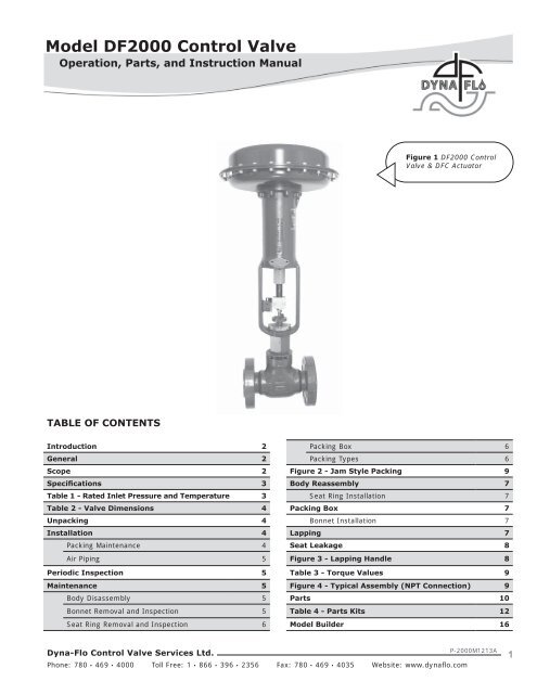
Model DF2000 Control Valve<br />
Operation, Parts, and Instruction Manual<br />
Figure 1 DF2000 Control<br />
Valve & DFC Actuator<br />
TABLE OF CONTENTS<br />
Introduction 2 Packing Box 6<br />
General 2 Packing Types 6<br />
Scope 2 Figure 2 - Jam Style Packing 9<br />
Specifications 3 Body Reassembly 7<br />
Table 1 - Rated Inlet Pressure and Temperature 3 Seat Ring Installation 7<br />
Table 2 - Valve Dimensions 4 Packing Box 7<br />
Unpacking 4 Bonnet Installation 7<br />
Installation 4 Lapping 7<br />
Packing Maintenance 4 Seat Leakage 8<br />
Air Piping 5 Figure 3 - Lapping Handle 8<br />
Periodic Inspection 5 Table 3 - Torque Values 9<br />
Maintenance 5 Figure 4 - Typical Assembly (NPT Connection) 9<br />
Body Disassembly 5 Parts 10<br />
Bonnet Removal and Inspection 5 Table 4 - Parts Kits 12<br />
Seat Ring Removal and Inspection 6 Model Builder 16<br />
Dyna-Flo Control Valve Services Ltd.<br />
Phone: 780 • 469 • 4000 Toll Free: 1 • 866 • 396 • 2356 Fax: 780 • 469 • 4035 Website: www.<strong>dyna</strong><strong>flo</strong>.com<br />
P-2000M1213A<br />
1
Model DF2000 Control Valve<br />
Operation, Parts, and Instruction Manual<br />
NOTICE<br />
These <strong>instruction</strong>s are meant to be used with the Dyna-Flo DF2000 Technical Bulletin as they refer to<br />
Figures and Tables therein. If you do not have the Technical Bulletin, contact Dyna-Flo immediately, or<br />
visit www.<strong>dyna</strong><strong>flo</strong>.com<br />
Each <strong>control</strong> valve is factory checked. Check the calibration for the specific application, before a valve<br />
is put into service.<br />
It is the intention of this document to provide users with an accurate guide for safe installation and<br />
maintenance of the DF2000 Control Valve. Revisions and updates are available at above mentioned<br />
website.<br />
INTRODUCTION<br />
The Model DF2000 Control Valves are heavy duty globe style <strong>control</strong> <strong>valves</strong> used in all kinds of demanding oil and gas applications,<br />
from well head to gas plant and beyond.<br />
The Model DF2000 <strong>control</strong> <strong>valves</strong> are post guided, single port <strong>valves</strong> that can be used for either throttling or on-off <strong>control</strong> of either<br />
liquids or gasses.<br />
The actuator for the Model DF2000 valve is typically a Dyna-Flo model DFC or DFO linear actuator. These heavy duty actuators are<br />
spring return diaphragm style, and can be used with or without a valve positioner.<br />
The Model DF2000 <strong>control</strong> <strong>valves</strong> are manufactured to a high level of quality specifications to ensure superior performance and<br />
customer satisfaction.<br />
GENERAL<br />
The following <strong>instruction</strong>s are to be thoroughly re<strong>view</strong>ed and understood prior to installing, operating or performing<br />
maintenance on this equipment. Work on this equipment should be performed by experienced personnel. Throughout<br />
the <strong>manual</strong>, safety and caution notes appear and must be strictly followed, to prevent serious injury or equipment<br />
malfunction.<br />
SCOPE<br />
The <strong>control</strong> valve configuration and construction materials were selected to meet particular pressure, temperature, and process<br />
conditions. Some material combinations are limited in their pressure and temperature ranges. Do not apply any other conditions to<br />
the valve without first contacting your Dyna-Flo sales office.<br />
This <strong>manual</strong> is written to be a practical and useful guide maintaining the Dyna-Flo DF2000 Control Valve.<br />
CAUTION<br />
To avoid personal injury or installation damage as a result of the sudden release of process pressure or the breaking of<br />
parts, do not install the valve assembly where service conditions could exceed the limits stated in this <strong>manual</strong> or on<br />
the equipment nameplates. Use government codes, accepted industry standards and good piping practices to select<br />
pressure-relieving equipment for protection of your installation. It is also important to wear the proper<br />
protective equipment when performing any installation or maintenance activity.<br />
Dyna-Flo Control Valve Services Ltd.<br />
Phone: 780 • 469 • 4000 Toll Free: 1 • 866 • 396 • 2356 Fax: 780 • 469 • 4035 Website: www.<strong>dyna</strong><strong>flo</strong>.com<br />
P-2000M1213A<br />
2
Model DF2000 Control Valve<br />
Operation, Parts, and Instruction Manual<br />
SPECIFICATIONS<br />
Valve Size, Flange Ratings, and Connections<br />
Size: 1” and 2”<br />
Rating: ASME 150 / 300 / 600 / 900 / 1500 / 2500<br />
Connections: RF / RTJ / NPT<br />
Rated Inlet Pressure and Temperature<br />
Per ASME B16.34 (See Table 1).<br />
Maximum Allowable Pressure Drops<br />
Flow-to-open: Capable of full rated pressure drops<br />
Flow-to-close: For more information contact your<br />
Dyna-Flo Sales Office<br />
(See Tables 7 & 8 of Sales Bulletin)<br />
Material Temperature Capabilities<br />
-50 to 450 o F (-45 to 232 o C) for standard LCC body.<br />
Construction Materials<br />
See Figure 4 for valve diagram and keys.<br />
See Parts List for construction materials.<br />
Dimensions<br />
Valve and Actuator assembly diagram - See Figure 4.<br />
Valve and Actuator assembly dimensions - See Tables 9 and<br />
10 of Sales Bulletin.<br />
Flow Direction<br />
Flow Up.<br />
Flow Characteristic<br />
Equal Percentage, others available upon request.<br />
Port, Yoke Boss and Stem Diameter, Rated Travel<br />
See Table 5 of Sales Bulletin.<br />
Valve Sizing Coefficients<br />
Port Size<br />
Max. Cv<br />
1/4” 1.64<br />
3/8” 4.03<br />
1/2” 6.82<br />
3/4” 14.00<br />
1” 23.70<br />
1-1/4” 34.50<br />
Detailed - See Table 3 of Sales Bulletin<br />
Sizing Coefficients<br />
See Sales Bulletin for: Fail Close Actuator - See Table 7<br />
Fail Open Actuator - See Table 8<br />
Valve Body and Actuator Approximate Weights<br />
See Table 6 of Sales Bulletin.<br />
Options<br />
• Trim in Tungsten Carbide<br />
• Anti-corrosion coating of internal body passage<br />
• Live loaded low emission packing<br />
For more information and other options contact your Dyna-Flo<br />
sales office.<br />
Rated Inlet Pressure and Temperature<br />
Valve Size Body Type Class ◊ Temperature Maximum Pressure<br />
NPT<br />
3750* (1500 ASME)<br />
6250* (2500 ASME)<br />
(2” Body Only)<br />
o<br />
F o<br />
C Psi Bar<br />
100 38 3,750 259<br />
450 232 3,425 236<br />
100 38 6,250 431<br />
450 232 5,710 394<br />
150 ASME<br />
100 38 290 20<br />
450 232 185 13<br />
1 and 2 Inch<br />
300 ASME<br />
100 38 750 52<br />
450 232 685 47<br />
Flanged<br />
600 ASME<br />
100 38 1,500 103<br />
450 232 1,370 94<br />
1500 ASME<br />
100 38 3,750 259<br />
450 232 3,425 236<br />
2500 ASME<br />
100 38 6,250 431<br />
(2” Body Only)<br />
450 232 5,710 394<br />
* Indicates Working Class Pressure (Psig) ◊ Indicates Class or Cold Working Pressure Limit<br />
Table 1<br />
Dyna-Flo Control Valve Services Ltd.<br />
Phone: 780 • 469 • 4000 Toll Free: 1 • 866 • 396 • 2356 Fax: 780 • 469 • 4035 Website: www.<strong>dyna</strong><strong>flo</strong>.com<br />
P-2000M1213A<br />
3
Model DF2000 Control Valve<br />
Operation, Parts, and Instruction Manual<br />
Port Size, Yoke Boss and Stem Diameter, Rated Travel Inch (mm)<br />
Valve Size<br />
1 Inch<br />
2 Inch<br />
Port Diameter<br />
Inch (mm)<br />
1/4 (6.4)<br />
3/8 (9.5)<br />
1/2 (12.7)<br />
3/4 (19.1)<br />
1/4 (6.4)<br />
3/8 (9.5)<br />
1/2 (12.7)<br />
3/4 (19.1)<br />
1 (25.4)<br />
1-1/4 (31.8)<br />
Yoke Boss<br />
Diameter<br />
Standard Inch (mm)<br />
Stem<br />
Diameter<br />
Rated Travel<br />
2-1/8 (54.0) 3/8 (9.5) 3/4 (9.5)<br />
2-13/16<br />
(71.4)<br />
1/2 (12.7) 3/4 (19.1)<br />
Yoke Boss<br />
Diameter<br />
2-13/16<br />
(71.4)<br />
3-9/16<br />
(90.5)<br />
Optional Inch (mm)<br />
Stem<br />
Diameter<br />
Table 2<br />
Rated Travel<br />
1/2 (12.7) 3/4 (19.1)<br />
3/4 (19.1) 3/4 (19.1)<br />
UNPACKING VALVE FROM SHIPPING CONTAINER<br />
Check the packing list against materials received, while unpacking the valve. The Packing List describes valve and accessories in<br />
each shipping container.<br />
When lifting the valve from shipping container, it is advisable to remove 2 actuator casing bolts, 180 o apart, and temporarily replace<br />
them with eye bolts and nuts. Position the lifting straps through the eye bolts to avoid damage to the tubing and mounted<br />
accessories.<br />
INSTALLATION<br />
Before installing the valve, clean dirt, welding chips, scale or other foreign material from the line.<br />
Look for signs of gasket leakage through the line flanges. Make repairs, if required.<br />
Check packing box bolting for proper tightness, stem leakage may be prevented by tightening the packing nuts. Reference Table 3<br />
for packing nut torque specifications.<br />
Packing Maintenance<br />
CAUTION<br />
Do not over tighten packing! This can cause excessive packing wear and high stem friction that may impede<br />
movement!<br />
If the packing is leaking and tightening the packing flange does not stop the leak then it is recommended that you remove the valve<br />
from the line.<br />
1 Install the valve with <strong>flo</strong>w through the valve in the direction as indicated by the arrow cast on the valve body. The valve<br />
assembly may be installed in any position unless limited by vibration considerations.<br />
NOTE<br />
The normal method of installation is with the actuator in vertical position above the valve body. In some<br />
non-vertical applications the actuator may need to be supported.<br />
Dyna-Flo Control Valve Services Ltd.<br />
Phone: 780 • 469 • 4000 Toll Free: 1 • 866 • 396 • 2356 Fax: 780 • 469 • 4035 Website: www.<strong>dyna</strong><strong>flo</strong>.com<br />
P-2000M1213A<br />
4
Model DF2000 Control Valve<br />
Operation, Parts, and Instruction Manual<br />
INSTALLATION (Continued)<br />
Packing Maintenance (Continued)<br />
WARNING<br />
Keep hands, hair and clothing away from all moving<br />
parts when operating the valve! Serious injury can<br />
result from failure to do so!<br />
2 When possible, stroke the valve and check for smooth<br />
operation through the full-stroke. Unsteady valve stem<br />
movement could be an indication of an internal problem.<br />
Air Piping<br />
The actuators are designed to accept 1/4” NPT connection. Use<br />
3/8” OD tubing (or equivalent) for all air lines. All connections<br />
must be free of leaks.<br />
CAUTION<br />
Do not exceed supply pressure indicated on serial<br />
plate located on the yoke of the actuator.<br />
PERIODIC INSPECTION<br />
CAUTION<br />
Use safe work practices and lock out procedures<br />
when isolating <strong>valves</strong> and actuators! Always be<br />
aware of flammable instrument gas!<br />
1 Avoid personal injury from sudden release of process<br />
pressure! Before performing any maintenance operation:<br />
A<br />
B<br />
C<br />
D<br />
Disconnect any power supply media lines providing air<br />
/ gas pressure, electric power, or a <strong>control</strong> signal to<br />
the actuator. Ensure the actuator cannot suddenly<br />
operate the valve.<br />
Isolate the valve from process pressure with bypass<br />
<strong>valves</strong> or completely shut off the process. Relieve<br />
process pressure, and drain the process fluid from the<br />
up and down stream of the valve.<br />
Vent the pneumatic actuator loading pressure and<br />
relieve any actuator spring preload.<br />
Use Safety lock-out procedures to be sure that the<br />
above provisions stay in effect while you complete the<br />
work on your equipment.<br />
2 Check for process fluid leakage to the atmosphere through<br />
the body to bonnet joint and (if equipped) any NPT<br />
connection.<br />
3 Examine the valve for damage caused by corrosive fumes<br />
or process drippings.<br />
4 Clean the valve and repaint areas of severe oxidation.<br />
5 Make sure positioner linkage (if equipped) and stem clamp<br />
are securely fastened. If the stem clamp is loose, check<br />
plug thread engagement and retighten. Refer to the<br />
Dyna-Flo Model DFC, or DFO Manual for detailed<br />
<strong>instruction</strong>s.<br />
6 Ensure all accessories, mounting brackets and fasteners<br />
are secure.<br />
7 Clean any dirt and foreign material from the plug stem.<br />
MAINTENANCE<br />
Body Disassembly<br />
1 Vent the pneumatic actuator loading pressure and relieve<br />
any actuator spring preload.<br />
CAUTION<br />
The body can be serviced in-line, after all process<br />
pressure and fluid are released. Remove if<br />
convenient. If the valve is to be serviced out of line,<br />
it is important that the body be firmly held in a<br />
clamping device. Serious injury can result from<br />
failure to do so!<br />
2 Once the body is secured, and any acutator spring preload<br />
relieved, remove the stem connector (Key 18) joining the<br />
valve stem to the actuator stem.<br />
ALL Key references to follow are from Figure 4.<br />
3 With a hammer and heavy chisel, strike the actuator yoke<br />
lock nut (Key 14) in a counter clockwise direction to loosen<br />
it, and remove the actuator. Actuator removal may require<br />
a second person, or the use of a hoist.<br />
Bonnet Removal and Inspection<br />
1 Remove the packing nuts (Key 12), note any corrosion or<br />
roughness in the threads.<br />
Dyna-Flo Control Valve Services Ltd.<br />
Phone: 780 • 469 • 4000 Toll Free: 1 • 866 • 396 • 2356 Fax: 780 • 469 • 4035 Website: www.<strong>dyna</strong><strong>flo</strong>.com<br />
P-2000M1213A<br />
5
Model DF2000 Control Valve<br />
Operation, Parts, and Instruction Manual<br />
MAINTENANCE (Continued)<br />
Bonnet Removal and Inspection (Continued)<br />
2 Remove the packing flange (Key 10). Note any corrosion<br />
and remove the stem wiper (Key 11) and packing follower<br />
(Key 9).<br />
3 DF2000 bonnets are factory tightened as show in Table 3.<br />
A large pipe wrench is commonly used to remove the<br />
bonnet. Once the bonnet is loosened it should move freely<br />
by hand. If the bonnet does not move freely be cautious of<br />
a build up of process pressure. Once the bonnet is<br />
disengaged from the body, carefully remove with the plug<br />
and stem still attached.<br />
4 Inspect the bonnet threads in the body for damage. Minor<br />
galling, or corrosion may require sandblasting.<br />
5 The bonnet gasket (Key 3) may come out with the bonnet<br />
assembly. If not, carefully remove the bonnet gasket from<br />
the body, avoid scratching the gasket surface.<br />
Packing Box<br />
1 With the bonnet removed from the body, pull the plug and<br />
stem assembly (Key 17) out of the bonnet (Key 2). The<br />
plug and stem assembly can then be reinserted to push the<br />
packing [packing box ring (Key 5), the bottom packing set<br />
(Key 6), packing spacer (Key 7), and the top packing set<br />
(Key 8)] out of the packing box.<br />
2 Retain the packing box ring, and spacer for use in the<br />
reassembly of the valve.<br />
3 With all the parts removed from the bonnet, clean and<br />
inspect all gasket and packing seating surfaces. Also,<br />
inspect bushing (Key 2a) for damage. Check threads for<br />
galling or corrosion.<br />
Packing Types<br />
The DF2000 is standard equipped with jam style packing, as<br />
shown in Figure 2.<br />
Seat Ring Removal and Inspection<br />
1 A 1-3/8” deep socket (non-impact type) with a 3/4” drive<br />
(for the 1” valve) and a 1-13/16” deep socket (non-impact<br />
type) with a 3/4” drive (for the 2” valve) are required.<br />
A standard mechanic’s “Pick Set” will help with the seat<br />
ring gasket removal (Key 15).<br />
2 Wipe the gasket sealing surface of the body and the<br />
bonnet and inspect for signs of leakage, corrosion, or other<br />
marks. Refer to the section on wear limits for guidance if a<br />
concern arises.<br />
3 Inspect the seat ring threads in the body for damage.<br />
Major galling, or corrosion may require sandblasting of the<br />
body to restore “as new” condition. Also, inspect the<br />
threads on the seat ring for signs of galling or corrosion.<br />
Packing Follower (Key 9)<br />
Packing Set (Key 8)<br />
Packing Set (Key 6)<br />
Lantern Ring (Key 7)<br />
4 Inspect the plug seating area, and the gasket surface of<br />
the seat ring for damage or marks of any kind. Deep marks<br />
are cause for replacement as the hard faced seat ring is<br />
difficult to recondition outside of the factory.<br />
* Key Numbers Correspond to Figure 4 Keys<br />
Packing Box Ring (Key 5)<br />
Lower Wiper (Key 4)<br />
Figure 2 Jam Style Packing<br />
Dyna-Flo Control Valve Services Ltd.<br />
Phone: 780 • 469 • 4000 Toll Free: 1 • 866 • 396 • 2356 Fax: 780 • 469 • 4035 Website: www.<strong>dyna</strong><strong>flo</strong>.com<br />
P-2000M1213A<br />
6
Model DF2000 Control Valve<br />
Operation, Parts, and Instruction Manual<br />
BODY REASSEMBLY<br />
Seat Ring Installation<br />
1 Clean and inspect the seat ring threads, and the threads in<br />
the body. A 1-3/8” deep socket (non-impact) with a 3/4”<br />
drive (for the 1” valve) and a 1-13/16” deep socket<br />
(non-impact) with a 3/4” drive (for the 2” valve) is<br />
required for seat ring (Key 16) installation. Coat both sides<br />
of the seat ring gasket (Key 15) with Nickel based<br />
anti-seize compound, and place the gasket carefully in<br />
the body. Completely coat the seat ring threads with Nickel<br />
based anti-seize compound, and place the seat ring into a<br />
clean body. Dry threads could prevent proper seating of<br />
the seat ring against the gasket, allowing leakage.<br />
2 Carefully use the deep socket and drive bar to thread the<br />
seat ring into place. The seat ring should turn smoothly<br />
into place. Any significant resistance should be<br />
investigated, and corrected to ensure proper assembly.<br />
Torque the seat ring as per torque values stated in Table 3.<br />
PACKING BOX<br />
1 Prepare the components for reassembling the packing box<br />
by using the appropriate packing lubricant on the lower<br />
wiper (Key 4) for the bottom of the packing box ring<br />
(Key 5). Carefully place the assembled packing box ring<br />
(Key 4 & 5) in place, in the bottom of a clean packing box.<br />
2 Lubricate the “V” of each PTFE packing ring (Key 6) and<br />
stack in a set as shown in Figure 2. There will be 2 sets of<br />
packing rings.<br />
3 Insert the bottom packing set with the open end of the “V”<br />
pointing down, over the valve stem. Avoid sliding the<br />
packing over any sharp edges that could damage the<br />
packing. Insert the packing spacer (Key 7), and then the<br />
top set of packing (Key 8) with the “V” again pointing<br />
down.<br />
Bonnet Installation<br />
1 Coat the large diameter guide section of the valve plug and<br />
stem assembly (Key 17) with mechanical assembly grease,<br />
and carefully place the plug into the seat ring (Key 16).<br />
2 Coat both sides of the bonnet gasket (Key 3) and bonnet<br />
threads with Nickel based anti-seize compound, and place<br />
the gasket carefully in a clean body.<br />
3 Lower the bonnet (Key 2) carefully over the stem and hand<br />
tighten into place.<br />
4 Torque the bonnet to the valve size appropriate to the<br />
torque value listed in Table 3. Insert the packing follower<br />
(Key 9) over the stem, into the packing box. Slide the stem<br />
wiper (Key 11) over the stem, down to the top of the<br />
packing follower (Key 9).<br />
5 Place the packing flange (Key 10) over the studs (Key 13)<br />
and stem, with the beveled stem hole side facing the<br />
packing follower (Key 9).<br />
6 Lubricate the exposed portion of the packing flange stud<br />
(Key 13) with Nickel based anti-seize compound and install<br />
the packing flange nuts (Key 12), with the material guide<br />
markings facing up. Tighten the nuts to the appropriate<br />
valve size torque value as indicated in Table 3.<br />
LAPPING<br />
If the seat ring and plug seating surface are in good condition,<br />
properly performed seat lapping can restore valve seat<br />
tightness.<br />
1 Clean the seating surface of the plug and seat ring with a<br />
400-600 grit emery cloth.<br />
2 Install the seat ring (Key 16) using the Body Reassembly<br />
<strong>instruction</strong>s.<br />
3 Apply 400-600 grit lapping compound to the seating area<br />
of the plug (Key 17).<br />
4 Insert the plug and stem (Key 17) into the bonnet (Key 2),<br />
without packing.<br />
5 Place bonnet (Key 2) and plug (Key 17) into the body<br />
(Key 1), and hand tighten bonnet.<br />
6 Insert the packing box follower (Key 9) into the bonnet to<br />
help align the stem.<br />
7 See Figure 3 on how to use 2 stem nuts and two 9/16” box<br />
end wrenches as a handle to lap the seat.<br />
CAUTION<br />
If you hear a squeaking noise during this operation,<br />
the seating area has become dry of lapping<br />
compound and galling of the surfaces could result.<br />
Dyna-Flo Control Valve Services Ltd.<br />
Phone: 780 • 469 • 4000 Toll Free: 1 • 866 • 396 • 2356 Fax: 780 • 469 • 4035 Website: www.<strong>dyna</strong><strong>flo</strong>.com<br />
P-2000M1213A<br />
7
Model DF2000 Control Valve<br />
Operation, Parts, and Instruction Manual<br />
LAPPING (Continued)<br />
8 While holding the wrenches and applying light pressure,<br />
make a 1/8 turn clockwise, and then a 1/8 turn counter<br />
clockwise.<br />
9 After 3 cycles of turning the plug and stem, lift the stem to<br />
pull lapping compound into the seating area.<br />
10 Repeat this process for 1 minute.<br />
12 Wipe the seating areas of the plug and seat ring.<br />
13 A fine “lap line” should be visible on the seating surface of<br />
the seat ring and valve plug. This should result in sound<br />
mating surfaces.<br />
NOTE<br />
If you do not see a full “lap line”, evaluate if a<br />
second round of lapping can remove the deviation.<br />
Deep marks will require machining.<br />
11 Remove the bonnet, plug and stem from the body.<br />
SEAT LEAKAGE<br />
The DF2000 is a metal seated valve and will leak a small amount under normal conditions. The leakage rate of the DF2000 allows a<br />
Class IV leakage rating to be applied under ASME / FCI 70-2. The standard also requires testing of the valve at the service pressure<br />
drop, or 50 psig (3.45 Bar), whichever is lower. Each DF2000 is shop tested to meet the allowable leakage rate that is a percentage<br />
of the port size maximum <strong>flo</strong>w rate.<br />
NOTE<br />
If you need “tight shut-off” at a high pressure drop, please consult your Dyna-Flo sales office.<br />
Figure 3 Lapping Handle<br />
Dyna-Flo Control Valve Services Ltd.<br />
Phone: 780 • 469 • 4000 Toll Free: 1 • 866 • 396 • 2356 Fax: 780 • 469 • 4035 Website: www.<strong>dyna</strong><strong>flo</strong>.com<br />
P-2000M1213A<br />
8
Model DF2000 Control Valve<br />
Operation, Parts, and Instruction Manual<br />
Torque Values<br />
Body Size<br />
Packing Box Nuts (Key 5)<br />
Minimum<br />
lbf-in. (N•m)<br />
Maximum<br />
lbf-in. (N•m)<br />
Seat Ring (Key 16)<br />
lbf-in. (N•m)<br />
1 40 (4.4) 50 (5.6) 3,600 (410)<br />
2 70 (7.8) 100 (11.1) 6,240 (710)<br />
Table 3<br />
Bonnet Hex (Key 2)<br />
lbf-in. (N•m)<br />
9,600 (1090)<br />
(2-5/8” hex)<br />
18,000 (2030)<br />
(3-1/4” hex)<br />
11<br />
12<br />
10<br />
13<br />
9<br />
14<br />
8<br />
5<br />
18<br />
7<br />
4<br />
6<br />
2a<br />
2<br />
17<br />
3<br />
16<br />
1<br />
15<br />
Figure 4<br />
Typical DF2000 Assembly<br />
with NPT Connections<br />
Dyna-Flo Control Valve Services Ltd.<br />
Phone: 780 • 469 • 4000 Toll Free: 1 • 866 • 396 • 2356 Fax: 780 • 469 • 4035 Website: www.<strong>dyna</strong><strong>flo</strong>.com<br />
P-2000M1213A<br />
9
Model DF2000 Control Valve<br />
Operation, Parts, and Instruction Manual<br />
Parts<br />
Key Description Part Number<br />
1 Body<br />
LCC<br />
1 Inch Contact Factory<br />
2 Inch Contact Factory<br />
2 Bonnet / Bushing Assembly<br />
LCC<br />
1 Inch 1DF2000B01D<br />
2 Inch 2DF2000B01D<br />
2a Bushing<br />
S17400 DH1150<br />
1 Inch Included with Key 2<br />
2 Inch Included with Key 2<br />
3 Bonnet Gasket<br />
S30400<br />
1 Inch 1B19823604D<br />
2 Inch 1B19843604D<br />
4 Lower Wiper<br />
PTFE<br />
1 Inch 1J87210699D<br />
2 Inch 1J87220699D<br />
5 Packing Box Ring<br />
S31600/S31603 Dual Grade<br />
1 Inch 1J87313507D<br />
2 Inch 1J87323507D<br />
6 & 8 Packing Set<br />
PTFE<br />
1 Inch 1R2900010DD<br />
2 Inch 1R2902010DD<br />
7 Packing Spacer<br />
S31600<br />
1 Inch 1F36413507D<br />
2 Inch 1J96233507D<br />
9 Packing Follower<br />
S31600/S31603 Dual Grade<br />
1 Inch 1E94393507D<br />
2 Inch 1E94433507D<br />
10 Packing Flange<br />
Plated Steel<br />
1 Inch 1E94372410D<br />
2 Inch 1E94422307D<br />
Key Description Part Number<br />
11 Outboard Seal Carrier<br />
Felt<br />
1 Inch 1J87260633D<br />
2 Inch 1J87270633D<br />
12 Packing Nut<br />
2H (2 Required)<br />
1 Inch 1E94402411D<br />
2 Inch 1E94452411D<br />
13 Packing Stud<br />
B7 (2 Required)<br />
1 Inch 1E94413103D<br />
2 Inch 1E94443103D<br />
14 Yoke Nut<br />
Zinc Plated Steel<br />
1 Inch 1E79302306D<br />
2 Inch 1E80742306D<br />
15 Seat Ring Gasket<br />
S30400<br />
1 Inch 1B19863604D<br />
2 Inch 1B19883604D<br />
16 Seat Ring (See Table 4)<br />
S31600/S31603 Dual Grade / Alloy 6<br />
1 Inch Valve<br />
1/4 Inch Port 2B5097X001D<br />
3/8 Inch Port 2B5098X001D<br />
1/2 Inch Port 2B5099X001D<br />
3/4 Inch Port 2B5100X001D<br />
2 Inch Valve<br />
1/4 Inch Port 2B5106X001D<br />
3/8 Inch Port 2B5107X001D<br />
1/2 Inch Port 2B5108X001D<br />
3/4 Inch Port 2B5109X001D<br />
1 Inch Port 2B5110X001D<br />
1-1/4 Inch Port 2K1801X001D<br />
S17400 DH1150<br />
1 Inch Valve<br />
1/4 Inch Port 2B5097X174D<br />
3/8 Inch Port 2B5098X174D<br />
1/2 Inch Port 2B5099X174D<br />
3/4 Inch Port 2B5100X174D<br />
Dyna-Flo Control Valve Services Ltd.<br />
Phone: 780 • 469 • 4000 Toll Free: 1 • 866 • 396 • 2356 Fax: 780 • 469 • 4035 Website: www.<strong>dyna</strong><strong>flo</strong>.com<br />
P-2000M1213A 10
Model DF2000 Control Valve<br />
Operation, Parts, and Instruction Manual<br />
Parts<br />
Key Description Part Number<br />
16 Seat Ring (Continued)<br />
S17400 DH1150<br />
1/4 Inch Port 2B5106X174D<br />
3/8 Inch Port 2B5107X174D<br />
1/2 Inch Port 2B5108X174D<br />
3/4 Inch Port 2B5109X174D<br />
1 Inch Port 2B5110X174D<br />
1-1/4 Inch Port 2K1801X174D<br />
17 Plug & Stem Assembly (See Table 4)<br />
Equal Percent<br />
S31600/S31603 Dual Grade / Alloy 6 & S20910<br />
1 Inch Valve<br />
1/4 Inch Port 2F1388X004D<br />
3/8 Inch Port 2F1389X003D<br />
1/2 Inch Port 2F1390X003D<br />
3/4 Inch Port 2F1391X003D<br />
2 Inch Valve<br />
1/4 Inch Port 2F1427X002D<br />
3/8 Inch Port 2F1428X002D<br />
1/2 Inch Port 2F1429X002D<br />
3/4 Inch Port 2F1430X002D<br />
1 Inch Port 2F1431X002D<br />
1-1/4 Inch Port 2L5331X003D<br />
S17400 DH1150 & S20910<br />
1 Inch Valve<br />
1/4 Inch Port 2F1388X174D<br />
3/8 Inch Port 2F1389X174D<br />
1/2 Inch Port 2F1390X174D<br />
3/4 Inch Port 2F1391X174D<br />
2 Inch Valve<br />
1/4 Inch Port 2F1427X174D<br />
3/8 Inch Port 2F1428X174D<br />
1/2 Inch Port SF1429X174D<br />
3/4 Inch Port 2F1430X174D<br />
1 Inch Port 2F1431X174D<br />
1-1/4 Inch Port 2L5331X174D<br />
1 Flute Dyna-Flute<br />
S31600/S31603 Dual Grade / Alloy 6 & S20910<br />
1 Inch Valve<br />
1/4 Inch Port Contact Factory<br />
Key Description Part Number<br />
2 Inch Valve<br />
1/4 Inch Port Contact Factory<br />
S17400 DH1150 & S20910<br />
1 Inch Valve<br />
1/4 Inch Port Contact Factory<br />
2 Inch Valve<br />
1/4 Inch Port Contact Factory<br />
Tungsten Carbide & S20910<br />
1 Inch Valve<br />
1/4 Inch Port Contact Factory<br />
2 Inch Valve<br />
1/4 Inch Port Contact Factory<br />
3 Flute Dyna-Flute<br />
S31600/S31603 Dual Grade / Alloy 6 & S20910<br />
1 Inch Valve<br />
1/4 Inch Port Contact Factory<br />
2 Inch Valve<br />
1/4 Inch Port Contact Factory<br />
S17400 DH1150 & S20910<br />
1 Inch Valve<br />
1/4 Inch Port Contact Factory<br />
2 Inch Valve<br />
1/4 Inch Port Contact Factory<br />
Tungsten Carbide & S20910<br />
1 Inch Valve<br />
1/4 Inch Port Contact Factory<br />
2 Inch Valve<br />
1/4 Inch Port Contact Factory<br />
Parts Ordering<br />
Whenever corresponding with Dyna-Flo about a Model DF2000<br />
<strong>control</strong> valve, refer to the actuator nameplate or the neck of the<br />
valve body for the unit serial number. Please order by the<br />
complete part number (as given in the Parts List) of each part<br />
required.<br />
Dyna-Flo Control Valve Services Ltd.<br />
Phone: 780 • 469 • 4000 Toll Free: 1 • 866 • 396 • 2356 Fax: 780 • 469 • 4035 Website: www.<strong>dyna</strong><strong>flo</strong>.com<br />
P-2000M1213A 11
Model DF2000 Control Valve<br />
Operation, Parts, and Instruction Manual<br />
Table 4<br />
DF2000 Parts Kits<br />
Part Number<br />
Description<br />
1” 2”<br />
S31600/S31603 Dual Grade / Alloy 6<br />
Plug (S20910 Stem) and Seat Ring,<br />
Double Packing Felt Wiper and Gaskets<br />
1/4 Inch Port Diameter RDXCNTRM11D RDXCNTRM21D<br />
3/8 Inch Port Diameter RDXCNTRM12D RDXCNTRM22D<br />
1/2 Inch Port Diameter RDXCNTRM13D RDXCNTRM23D<br />
3/4 Inch Port Diameter RDXCNTRM14D RDXCNTRM24D<br />
1 Inch Port Diameter N/A RDXCNTRM25D<br />
1-1/4 Inch Port Diametert N/A RDXCNTRM26D<br />
S31600/S31603 Dual Grade / Tungsten Carbide<br />
Plug (S20910 Stem) and Seat Ring<br />
1/4 Inch Port Diameter TDX1000007D TDX2000007D<br />
3/8 Inch Port Diameter TDX1000008D TDX2000008D<br />
1/2 Inch Port Diameter TDX1000009D TDX2000009D<br />
3/4 Inch Port Diameter TDX1000010D TDX2000010D<br />
1 Inch Port Diameter N/A TDX2000011D<br />
1-1/4 Inch Port Diameter N/A TDX2000012D<br />
Bonnet Gasket, Seat Ring Gasket, Packing<br />
Gasket Set & Packing - NACE RDX0000CN1D RDX0000CN2D<br />
Dyna-Flo Control Valve Services Ltd.<br />
Phone: 780 • 469 • 4000 Toll Free: 1 • 866 • 396 • 2356 Fax: 780 • 469 • 4035 Website: www.<strong>dyna</strong><strong>flo</strong>.com<br />
P-2000M1213A 12
Model DF2000 Control Valve<br />
Operation, Parts, and Instruction Manual<br />
Our Commitment to Quality<br />
Dyna-Flo is committed to continuous improvement. While all efforts have been made to ensure the accuracy of the content in<br />
this document, modifications or improvements to the information, specifications, and designs may occur at any time without<br />
notice. This document was published for informational purposes only, and does not express or imply suitability, a warranty,<br />
or guarantee regarding the products or services described herein or their use or applicability.<br />
Neither Dyna-Flo Control Valve Services Ltd., nor any of their affiliated entities assumes responsibility for the selection, use<br />
and maintenance of any product. Responsibility for selection, use and maintenance of any product remains with the purchaser<br />
and end-user.<br />
Dyna-Flo Control Valve Services Ltd.<br />
Phone: 780 • 469 • 4000 Toll Free: 1 • 866 • 396 • 2356 Fax: 780 • 469 • 4035 Website: www.<strong>dyna</strong><strong>flo</strong>.com<br />
P-2000M1213A 13
Model DF2000 Control Valve<br />
Operation, Parts, and Instruction Manual<br />
This page left blank intentionally.<br />
Dyna-Flo Control Valve Services Ltd.<br />
Phone: 780 • 469 • 4000 Toll Free: 1 • 866 • 396 • 2356 Fax: 780 • 469 • 4035 Website: www.<strong>dyna</strong><strong>flo</strong>.com<br />
P-2000M1213A 14
Model DF2000 Control Valve<br />
Operation, Parts, and Instruction Manual<br />
This page left blank intentionally.<br />
Dyna-Flo Control Valve Services Ltd.<br />
Phone: 780 • 469 • 4000 Toll Free: 1 • 866 • 396 • 2356 Fax: 780 • 469 • 4035 Website: www.<strong>dyna</strong><strong>flo</strong>.com<br />
P-2000M1213A 15
Model DF2000 Control Valve<br />
Operation, Parts, and Instruction Manual<br />
Ordering Guide<br />
Dyna-Flo DF2000 Control Valve | Model Numbering System<br />
Sample Part Number<br />
DF2000 - 2AF - 2DE - S1<br />
1<br />
S<br />
E<br />
Code Description<br />
Shut Off Classification<br />
1 Class IV (Standard)<br />
2 Class V (Optional)<br />
S<br />
T<br />
E<br />
T<br />
Valve Trim Material<br />
S31600* / Alloy 6 (standard)<br />
Tungsten Carbide<br />
Characteristic<br />
Equal Percent<br />
Dyna-Flute (3 Flute)<br />
F<br />
H<br />
S17400 DH1150<br />
Dyna-Flute (1 Flute)<br />
Packing Style<br />
D<br />
D<br />
L<br />
Double PTFE (standard)<br />
Live Loaded PTFE<br />
G<br />
Single Graphite<br />
2<br />
Orifice Size<br />
2 1/4 Inch Port<br />
3 3/8 Inch Port<br />
4 1/2 Inch Port<br />
6 3/4 Inch Port<br />
8 1 Inch Port (2 Inch Body Only)<br />
1 1-1/4 Inch Port (2 Inch Body Only)<br />
F<br />
Connection Style<br />
F RF N NPT<br />
J RTJ<br />
A<br />
A<br />
B<br />
C<br />
N<br />
ASME Class / CWP<br />
150 Flanged<br />
D 900 / 1500 Flanged<br />
300 Flanged<br />
E CWP 3750 NPT (ASME 1500)<br />
600 Flanged<br />
F 2500 Flanged (2” Valve Only)<br />
CWP 6250 NPT (ASME 2500)(2” Valve Only)<br />
2<br />
-<br />
DF2000<br />
Body Size (Mounting Connection / Stem Size)<br />
1 1 Inch Body (2-1/8” / 3/8”)<br />
2 2 Inch Body (2-13/16 / 1/2”)<br />
3 2 Inch Body (3-9/16” / 3/4”)<br />
Body Material<br />
- LCC M CF8M<br />
Body Style<br />
DF2000 Globe DF2000A Angle<br />
* All S31600 barstock is dual grade S31600/S31603 (316/316L).<br />
Dyna-Flo Control Valve Services Ltd.<br />
Phone: 780 • 469 • 4000 Toll Free: 1 • 866 • 396 • 2356 Fax: 780 • 469 • 4035 Website: www.<strong>dyna</strong><strong>flo</strong>.com<br />
P-2000M1213A 16