view dfc instructions (pdf) - dyna-flo control valves
view dfc instructions (pdf) - dyna-flo control valves
view dfc instructions (pdf) - dyna-flo control valves

Create successful ePaper yourself
Turn your PDF publications into a flip-book with our unique Google optimized e-Paper software.
Model DFC Valve Actuator<br />
Operation, Parts, and Instruction Manual<br />
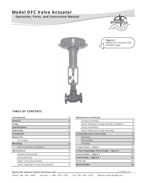
Figure 1<br />
Model DFC Actuator and<br />
DF2000 Valve<br />
TABLE OF CONTENTS<br />
Introduction 2 Maintenance Continued<br />
General 2 Actuator Assembly 8<br />
Scope 2 Lower Diaphragm Casing Bushing Installation 8<br />
Specifications 3 Spring Installation 8<br />
Unpacking 4 Upper Diaphragm Casing Assembly 8<br />
Installation 4 Casing Mounted Travel Stops 9<br />
Bench Set 4 Adjusting 9<br />
Air to Open 5 Disassembly 9<br />
Mounting 5 Assembly 10<br />
Stem Connection Installation 6 Torque Chart - Table 2 11<br />
Maintenance 7 2 Piece Diaprhagm Plate Design - Figure 6 11<br />
Actuator Disassembly 7 Cross Section - Figure 7 12<br />
Spring Removal 7 Travel Stops - Figure 8 13<br />
Upper Casing Disassembly 7 Parts List 14<br />
Lower Diaphragm Casing Disassembly 8 Model Builder 20<br />
Dyna-Flo Control Valve Services Ltd.<br />
Phone: 780 • 469 • 4000 Toll Free: 1 • 866 • 396 • 2356 Fax: 780 • 469 • 4035 Website: www.<strong>dyna</strong><strong>flo</strong>.com<br />
P-DFCM0613A<br />
1
Model DFC Valve Actuator<br />
Operation, Parts, and Instruction Manual<br />
NOTICE<br />
These <strong>instructions</strong> are meant to be used with the Dyna-Flo DFC / DFO Technical Bulletin as they refer to<br />
Figures and Tables therein. If you do not have the Technical Bulletin, contact Dyna-Flo immediately, or<br />
visit www.<strong>dyna</strong><strong>flo</strong>.com<br />
Each <strong>control</strong> valve is factory checked. Check the calibration for the specific application, before a valve<br />
is put into service.<br />
It is the intention of this document to provide users with an accurate guide for safe installation and<br />
maintenance of the DFC Valve Actuator. Revisions and updates are available at above mentioned website.<br />
INTRODUCTION<br />
The Model DFC series linear output spring and diaphragm actuators are used in all kinds of demanding applications. The large area<br />
of the diaphragm allows low-pressure operation, and the spring provides fail safe positioning of a <strong>control</strong> valve on loss of the<br />
pneumatic supply. Model DFC actuators are used to automate <strong>control</strong> <strong>valves</strong> in both throttling and on/off <strong>control</strong> of liquids or gases.<br />
When combined with a Dyna-Flo Model DF2000 or 360 <strong>control</strong> valve, the DFC is part of a rugged <strong>control</strong> valve assembly, to which a<br />
wide variety of <strong>control</strong>lers and instruments can be attached.<br />
Dyna-Flo’s high level of quality specifications used in manufacturing the Model DFC and DFO series linear pneumatic actuators<br />
ensures superior performance and customer satisfaction.<br />
GENERAL<br />
The following <strong>instructions</strong> are to be thoroughly re<strong>view</strong>ed and understood prior to installing, operating or performing<br />
maintenance on this equipment. Work on this equipment should be done by experienced personnel. Throughout the<br />
manual, safety and caution notes appear and must be strictly followed to prevent serious injury or equipment<br />
malfunction.<br />
SCOPE<br />
This manual will provide detailed information on the complete disassembly and reassembly of the Model DFC pneumatic actuator.<br />
Refer to seperate instruction manuals for the installation of positioners and all other accessories used with these actuators. Do not<br />
apply any other conditions to the actuator without first contacting your Dyna-Flo sales office.<br />
This manual is written to be a practical and useful guide to successfully using the Dyna-Flo Model DFC for many years.<br />
CAUTION<br />
To avoid personal injury or installation damage as a result of the sudden release of process pressure or the breaking<br />
of parts, do not install the actuator assembly where service conditions could exceed the limits stated in this manual<br />
or on the equipment nameplates. Only well trained experienced technicians should perform these procedures.<br />
Be sure to use safe work practices and lockout procedures. Always be aware of the hazards of spring-loaded<br />
actuators. Be sure that they are in the failed (de-energized) position before performing any maintenance procedure.<br />
These actuators have dangerous pinch points. Never put your hands inside the valve unless you are certain that the<br />
actuator cannot move.<br />
Dyna-Flo Control Valve Services Ltd.<br />
Phone: 780 • 469 • 4000 Toll Free: 1 • 866 • 396 • 2356 Fax: 780 • 469 • 4035 Website: www.<strong>dyna</strong><strong>flo</strong>.com<br />
P-DFCM0613A<br />
2
Model DFC Valve Actuator<br />
Operation, Parts, and Instruction Manual<br />
Table 1<br />
Model DFC Actuator Specifications<br />
SPECIFICATION<br />
Nominal Effective Area<br />
Yoke Boss Diameter<br />
Acceptable Valve Stem Diameter<br />
Maximum Allowable Output Thrust<br />
ACTUATOR SIZE<br />
1069 2069 2105 2156 3105 3156 3220 (1)<br />
inch 2 69 69 105 156 105 156 220<br />
cm 2 445 445 667 1006 677 1006 1419<br />
inch 2-1/8 2-13/16 2-13/16 2-13/16 3-9-16 3-9/16 3-9/16<br />
mm 54 71 71 71 90 90 90<br />
inch 3/8 1/2 1/2 1/2 3/4 3/4 3/4<br />
mm 9.5 12.7 12.7 12.7 19.1 19.1 19.1<br />
lb 2300 2700 5650 7550 5650 6800 8800<br />
N 10,230 12,010 25,131 33,582 25,131 30,246 39,142<br />
Maximum Travel (2)<br />
Standard<br />
Top-Loaded<br />
inch 1-1/8 1-1/2 2 2 2 2 3 (3)<br />
mm 29 38 51 51 51 51 76<br />
inch 3/4 --- 3/4 --- --- 1-1/8 ---<br />
mm 19 --- 19 --- --- 29 ---<br />
Maximum Casing Pressure for<br />
Psig 70 70 65 55 65 55 50<br />
Actuator Sizing (4,5) Bar 4.83 4.83 4.48 3.79 4.48 3.79 3.45<br />
Maximum Excess Diaphragm<br />
Psig 20 20 10 10 10 10 10<br />
Pressure (4) Bar 1.38 1.38 0.69 0.69 0.69 0.69 0.69<br />
Maximum Diaphragm Casing<br />
Psig 90 90 75 65 75 65 60<br />
Pressure (4,5) Bar 6.21 6.21 5.17 4.48 5.17 4.48 4.14<br />
Approximate Weight<br />
Material<br />
Temperature<br />
Capabilities<br />
lbs 48 50 90 121 94 122 254<br />
Kg 22 23 41 55 43 55 115<br />
Nitrile Elastomers -40 to 180 o F (-40 to 82 o C)<br />
Silicone Elastomers -65 to 300 o F (-54 to 149 o C)<br />
NOTES:<br />
(1) These values also apply to the DFC Size 3220-4 actuator.<br />
(2) Actuator travel may be less than the value listed after connected to the valve.<br />
(3) Maximum actuator travel for the 3220-4 is 4 inches (102 mm).<br />
(4) See Specification section for definitions.<br />
(5) This Maximum Casing Pressure is not to be used for normal operating pressure. Its purpose is to allow for<br />
typical regulator supply settings and/or relief valve tolerances.<br />
Dyna-Flo Control Valve Services Ltd.<br />
Phone: 780 • 469 • 4000 Toll Free: 1 • 866 • 396 • 2356 Fax: 780 • 469 • 4035 Website: www.<strong>dyna</strong><strong>flo</strong>.com<br />
P-DFCM0613A<br />
3
Model DFC Valve Actuator<br />
Operation, Parts, and Instruction Manual<br />
The actuator must be installed on the valve before being<br />
installed into the pipeline. Ensure that the travel has been<br />
checked; refer to the Bench Settin Actuator section (below)<br />
for detailed <strong>instructions</strong> on this procedure.<br />
BENCH SETTING ACTUATOR<br />
(Refer to Figure 3)<br />
CAUTION<br />
To prevent valve stem damage perform the bench<br />
setting with actuator removed from valve<br />
UNPACKING<br />
Figure 2 Lifting Hooks<br />
Check the Packing List against materials recieved, while<br />
unpacking the actuator. The Packing List describes actuator and<br />
accessories in each shipping container.<br />
When lifting the actuator from the shipping container, it is<br />
recommended the lifting hooks attached to the actuator casing<br />
be used (see Figure 2). If there are no lifting hooks, it is<br />
advisable to remove 2 actuator casing bolts, 180 o apart, and<br />
temporarily replace them with eye bolts and nuts. Position the<br />
lifting straps through the lifting hooks or eye bolts to avoid<br />
damage to the tubing and mounted accessories.<br />
INSTALLATION<br />
CAUTION<br />
Do not use an operating pressure that exceeds the<br />
Maximum Diaphragm Casing Pressure (See Table 1).<br />
Also make sure that the operating pressure does not<br />
create a force on the actuator stem that is greater<br />
than the Maximum Allowable Output Thrust (See<br />
Table 1).<br />
If the actuator has been installed on the valve in the factory,<br />
the assembly is ready to be placed inline. Refer to the proper<br />
Dyna-Flo valve manual for installation. Refer to the Mounting:<br />
Actuator to Valve section (Page 5) for detailed <strong>instructions</strong> on<br />
how to install the actuator on the valve.<br />
CAUTION<br />
The following procedures must be completed before<br />
installing the stem connector (Key 22) between the<br />
actuator stem (Key 3) and the valve stem (Key 31).<br />
Except for the DFC Size 3220, the stem connector<br />
assembly (Key 22) will need to be installed to<br />
prevent the stem from rotating while adjusting the<br />
bench set.<br />
1 To properly verify bench setting 3 pieces of information are<br />
required:<br />
A<br />
B<br />
C<br />
Upper Bench Set Loading Pressure.<br />
Lower Bench Set Loading Pressure<br />
(example: on a 10-30 Psig bench set, 10 is the lower<br />
and 30 Psig is the upper).<br />
Travel.<br />
This information is available on the actuator name plate<br />
(Key 33). If information is missing or incomplete contact<br />
your Dyna-Flo Sales Office.<br />
2 Before applying pressure to the actuator make sure that<br />
the spring (Key 2) is properly seated onto the spring seat<br />
(Key 20) (not required on a new factory assembled<br />
actuator).<br />
3 Connect a supply line with a gauge that can accurately<br />
measure both 0 Psi and the upper bench set pressure.<br />
4 Apply maximum casing pressure to the actuator to verify<br />
seal integrity is good. Use a soapy solution to check for any<br />
air leaks from the lower casing gasket (Key 13) and the<br />
diaphragm (Key 7). On a new actuator this will have been<br />
done a the factory and won’t be required.<br />
Dyna-Flo Control Valve Services Ltd.<br />
Phone: 780 • 469 • 4000 Toll Free: 1 • 866 • 396 • 2356 Fax: 780 • 469 • 4035 Website: www.<strong>dyna</strong><strong>flo</strong>.com<br />
P-DFCM0613A<br />
4
Model DFC Valve Actuator<br />
Operation, Parts, and Instruction Manual<br />
*Note: Distance<br />
of Travel Should<br />
Match Specification<br />
Given on Name Plate<br />
(Key 33)<br />
Travel Scale Adjusted<br />
To Coincide With The<br />
Travel Of The Travel<br />
Indicator Disk After<br />
Actuator Has Been<br />
Mounted To Valve<br />
Magnet/Ruler<br />
Combination Setup<br />
Mark Upper<br />
Bench Set<br />
Loading<br />
Pressure<br />
Mark Lower<br />
Bench Set<br />
Loading<br />
Pressure<br />
Travel<br />
Indicator<br />
Disk<br />
(Key 27)<br />
Upper Bench<br />
Set Loading<br />
Pressure Mark<br />
Lower Bench<br />
Set Loading<br />
Pressure Mark<br />
Rated Valve<br />
Travel Scale<br />
(Key 24)<br />
Figure 3 Bench Set Spring Adjustment Diagram<br />
For Air to Open Valves<br />
1 Apply the upper bench set loading pressure plus 5 Psi<br />
(0.34 Bar) to the actuator and note where stem travel<br />
stops, this should occur when the travel stop (Key 10)<br />
encounters the upper casing (Key 5). The intent is for the<br />
travel stop to contact the upper casing at the exact time<br />
the upper bench set loading value is reached. Apply 5 Psi<br />
(0.34 Bar) above and below the upper bench set value to<br />
verify this. (Example: for a 10-30 bench set the travel stop<br />
should contact the upper casing at exactly 30 Psig) If stem<br />
(Key 3) travel stops before or after the upper bench set<br />
value, the spring adjuster (Key 21) will need to be adjusted<br />
to obtain the proper bench set. You may need to relieve<br />
pressure to the actuator in order to adjust the spring<br />
adjuster. Turning the spring adjuster up (towards the top<br />
of the actuator) will increase the bench set pressure.<br />
2 Once the upper bench set pressure has been set, use a<br />
magnet or piece of tape to attach a piece of metal or ruler<br />
to the bottom of the actuator stem (Key 3) to use as an<br />
indicator arm. Make a mark to indicate the stem position<br />
at the upper bench set pressure (See Figure 3). Make sure<br />
the travel is fully extended.<br />
3 Adjust the gauge to the lower bench set pressure and mark<br />
the actuator stem position. The measurement between the<br />
upper and lower bench set marks should equal the travel<br />
indicated on the name-plate within 1/16” (1.6 mm).<br />
NOTE<br />
If these steps do not allow you to reach the proper<br />
bench set pressure then an incorrect or damaged<br />
spring may be the problem. Contact your Dyna-Flo<br />
Sales Office for more information.<br />
MOUNTING: ACTUATOR TO VALVE<br />
CAUTION<br />
During mounting the actuator stem and valve stem<br />
could come into contact with each other. Ensure that<br />
the valve stem is pushed down before trying to<br />
install the actuator, doing this will help to protect<br />
the stem threads from getting damaged.<br />
CAUTION<br />
It may be necessary to apply loading pressure to the<br />
actuator temporarily to move the actuator stem and<br />
allow for more clearance between it and the valve<br />
stem. Use extreme caution when moving the<br />
pressurized actuator; ensure that no clothing, hair,<br />
hands or tools come in between the two stems or<br />
moving parts. If loading pressure fails personal<br />
injury or property damage may occur.<br />
1 Make sure the valve is securely supported using a vice or<br />
similar method before proceeding. It is advised to place<br />
valve on a surface that will be able to support the<br />
combined weight of valve and actuator.<br />
Dyna-Flo Control Valve Services Ltd.<br />
Phone: 780 • 469 • 4000 Toll Free: 1 • 866 • 396 • 2356 Fax: 780 • 469 • 4035 Website: www.<strong>dyna</strong><strong>flo</strong>.com<br />
P-DFCM0613A<br />
5
Model DFC Valve Actuator<br />
Operation, Parts, and Instruction Manual<br />
MOUNTING: ACTUATOR TO VALVE<br />
(Continued)<br />
2 Make sure the stem is pushed down away from the<br />
actuator. Thread the two nuts (Keys 28 & 29) all the way<br />
onto the valve stem. Install the travel disk (Key 27) onto<br />
the valve stem (concave side down) so that it rests on the<br />
jam nuts. NOTE: with the travel disk on the stem it may<br />
not be possible to mount the actuator because the travel<br />
disk will not slide through the yoke boss mounting area.<br />
Before attempting to mount the actuator check to see that<br />
the disk will go through the yoke boss mounting area. If<br />
not, the travel disk will need to be inserted on the stem<br />
after the yoke nut (Key 32). Place the travel disk overtop of<br />
the yoke nut during the yoke nut installation process.<br />
3 Be sure to have the yoke nut (Key 32) sitting inside the<br />
actuator yoke or have the yoke nut ready to be placed in<br />
between the actuator stem and valve stem when lowering<br />
the actuator onto the valve. Carefully lift and lower the<br />
actuator onto the valve, this may require more than one<br />
person or a heavy lifting device. Once on the valve,<br />
orientate the actuator to be properly aligned parallel with<br />
the valve body (See Figure 5).<br />
4 Thread the yoke nut onto the valve bonnet and tighten<br />
using a heavy blunted chisel and hammer until the yoke is<br />
secured tightly to the valve (Refer to Figure 4). DO NOT<br />
OVER TIGHTEN.<br />
Stem Connector Installation<br />
1 Apply upper loading pressure plus 5 Psi (0.34 Bar) to the<br />
actuator if loading pressure was not applied prior to<br />
mounting. This should put the actuator in the fully up<br />
position.<br />
2 Install the travel scale (Key 24) to the actuator using the<br />
speed nuts (Key 26) and machine screws (Key 25). Position<br />
the travel disk (Key 27) on top of the jam nuts at the bottom<br />
of the travel scale (Key 24) by adjusting the jam nuts<br />
(Keys 28 & 29). Carefully move the plug / stem up until<br />
the travel disk indicates full travel as indicated on the<br />
travel scale. The movement of the plug / stem must be<br />
done with caution not to damage the stem.<br />
3 As shown in Figure 3, the valve stem should fit inside the<br />
actuator stem. Install the stem connector (Key 22). It is<br />
important to position the stem connector so that the<br />
threads properly engage with those of the stems.<br />
Connect the other half of the stem connector and orientate<br />
the stem connector as show in Figure 3. It is at this time<br />
that any accessories (such as positioner arms) that need to<br />
be connected to the stem connector should be put in place.<br />
Install the stem connector bolts and tighten.<br />
4 Re-position the travel disk (Key 27) under the stem<br />
connector (Key 22), thread up the jam nuts (Keys 28 & 29)<br />
to hold the travel disk in place and tighten the jam nuts<br />
together (Refer to Figure 3). Do not over tighten the jam<br />
nuts.<br />
5 Apply pressure and stroke the valve several times. Loosen<br />
the travel scale (Key 24) and reposition it to align with the<br />
closed position of the valve and verify that the travel is still<br />
accurate to the value indicated on the name plate (Key<br />
33). If travel is inaccurate it may be necessary to repeat<br />
the stem connector procedures or to refer back to Bench<br />
Setting Actuator.<br />
Figure 4 Yoke Nut Loosening<br />
Dyna-Flo Control Valve Services Ltd.<br />
Phone: 780 • 469 • 4000 Toll Free: 1 • 866 • 396 • 2356 Fax: 780 • 469 • 4035 Website: www.<strong>dyna</strong><strong>flo</strong>.com<br />
P-DFCM0613A<br />
6
Model DFC Valve Actuator<br />
Operation, Parts, and Instruction Manual<br />
MAINTENANCE<br />
WARNING<br />
Disconnect all power lines and pneumatic lines<br />
making sure the actuator is depressurized prior to<br />
commencing disassembly. Remove any power source<br />
that may cause the actuator to spontaneously move.<br />
Also, relieve any spring pressure or compression<br />
before you start the disassembly process, this can be<br />
done by lowering the spring adjuster (Key 21).<br />
CAUTION<br />
Use bypass <strong>valves</strong> or completely shut off process<br />
media to isolate the valve from the process pressure<br />
and fluids. Relieve process pressure and drain<br />
process media from both side of the valve.<br />
Actuator Disassembly<br />
1 Make sure that the valve and actuator are securely<br />
supported and that valve body is clamped in place and<br />
unable to move during disassembly.<br />
2 Completely remove spring compression by turning the<br />
spring adjuster (Key 21) until loose. Once spring<br />
compression is removed disassemble the stem connector<br />
(Key 22) and remove both halves. Inspect all the threads<br />
on both halves of the stem connector and make sure there<br />
is no damage.<br />
3 If removal of the actuator from the valve is necessary, the<br />
yoke nut (Key 32) will need to be completely loosened.<br />
Using a heavy blunted chisel and hammer, completely<br />
loosen the yoke nut (Key 32) (Refer to Figure 4).<br />
NOTE: the yoke nut will not be able to be removed until<br />
the actuator is lifted from the valve (Refer to Unpacking<br />
and Mounting sections for actuator hoisting <strong>instructions</strong>).<br />
4 Before work begins make sure that the actuator is secured<br />
in place and properly supported.<br />
Spring removal<br />
1 Unscrew the spring adjuster (Key 21) and remove it from<br />
the actuator stem. With the spring adjuster removed it is<br />
possible to remove the spring seat (Key 20) from the yoke<br />
(Key 1). Inspect the threads of the spring adjuster and for<br />
damage and corrosion. Also, inspect the spring.<br />
Upper Diaphragm Casing Disassembly<br />
1 Remove all the diaphragm casing cap screws (Key 18) and<br />
nuts (Key 19). Lift the upper diaphragm casing (Key 5)<br />
from the actuator.<br />
2 From the top of the open actuator remove the hex head<br />
bolt (Key 11) and travel stop (Key 10). The actuator stem<br />
(Key 3) may rotate during hex head bolt removal, it may<br />
be necessary to hold the stem or tap the wrench with a<br />
hammer to loosen the bolt. Use extreme caution and avoid<br />
damaging the actuator stem during this process. Remove<br />
the stem from the yoke mounting end.<br />
3 Being careful not to damage the actuator stem (Key 3)<br />
remove it from the actuator. Inspect the actuator stem for<br />
thread damage, deep scratches and corrosion. Minor<br />
scratches and corrosion can be polished out (scratches that<br />
will not stop your fingernail are considered minor), if there<br />
are deep scratches, corrosion or damage the actuator stem<br />
will need to be replaced.<br />
4 Remove the upper diaphragm plate (Key 8) from the<br />
actuator and diaphragm (Key 7), inspect the plate for<br />
cracks and wear. NOTE: on older actuators the upper<br />
diaphragm plate maybe composed of two separate pieces.<br />
Inspect the diaphragm for tears, abnormal stretching,<br />
cracks and pliability. If the diaphragm is brittle, torn or<br />
cracked it will need to be replaced.<br />
5 Remove the lower diaphragm plate and inspect it for any<br />
cracks, wear or corrosion.<br />
6 Using a pair of pliers or other tool, remove the snap ring<br />
(Key 14) from the yoke (it sits overtop of the bushing (Key<br />
15). Replace if necessary.<br />
7 Remove the bushing (Key 15) from the actuator being<br />
careful not to damage the bushing, seals or actuator yoke.<br />
The actuator stem (Key 3) and spring adjuster (Key 21)<br />
may be used with extreme caution to remove the bushing.<br />
By threading the spring adjuster part way onto the<br />
actuator stem the assembly may be inserted up into the<br />
yoke and used as a plunger to push out the bushing.<br />
8 Using a pick set or small screwdriver, remove the o-rings<br />
(Keys 16 & 17) from the bushing being careful not to<br />
damage bushing surfaces. Inspect the sealing surfaces of<br />
the bushing for deep scratches and corrosion, replace if<br />
necessary. O-rings and gaskets should normally be<br />
replaced during maintenance.<br />
Dyna-Flo Control Valve Services Ltd.<br />
Phone: 780 • 469 • 4000 Toll Free: 1 • 866 • 396 • 2356 Fax: 780 • 469 • 4035 Website: www.<strong>dyna</strong><strong>flo</strong>.com<br />
P-DFCM0613A<br />
7
Model DFC Valve Actuator<br />
Operation, Parts, and Instruction Manual<br />
Lower Diaphragm Casing Removal<br />
1 Remove the lower diaphragm casing cap screws (Key 18)<br />
and lift lower diaphragm casing (Key 4) off of the yoke<br />
(Key 1). Remove the lower casing gasket (Key 13) clean<br />
and inspect the yoke / lower casing sealing surfaces for<br />
damage. O-rings and gaskets should be replaced during<br />
maintenance.<br />
NOTE<br />
For the DFC Size 3220 inspect the o-ring groove on<br />
the top surface of the yoke (Key 1) for any deep<br />
scratching or corrosion. Also check the lower<br />
diaphragm casing (Key 4) for any deformation<br />
excessive tightening may have caused. O-rings<br />
and gaskets should be replaced during maintenance.<br />
Actuator Assembly<br />
CAUTION<br />
Before assembling the actuator, make sure that the<br />
yoke and actuator are securely supported with a<br />
clamping device and on a surface that will support<br />
the assembled actuator weight.<br />
NOTE<br />
Use an anti-seize compound that is approved for the<br />
service conditions that the actuator is being installed<br />
into.<br />
Lower Diaphragm Casing Bushing Installation<br />
1 Coat the lower diaphragm gasket (Key 13) with anti-seize<br />
compound and place on to the yoke (Key 1) (on a DFC size<br />
3220 actuator there is an o-ring in place of the gasket).<br />
The holes of the gasket should align with the holes on the<br />
yoke.<br />
2 Install the lower diaphragm casing (Key 4), tighten cap<br />
screws (Key 12) using a criss-cross pattern. DO NOT over<br />
tighten the cap screws as excessive tightening could warp<br />
the casing or deflect and cause the gasket to leak.<br />
3 Lubricate the bushing seals (Keys 16 & 17) with siliconebased<br />
lubricant and place them into the bushing (Key 15)<br />
as shown in Figure 6. Pack the inside of the bushing with<br />
lubricant (Lubriplate ® Mag-1 or equivalent) and insert the<br />
bushing into the yoke (Key 1). The bushing is held in place<br />
with the snap ring (Key 14) that fits into the groove in the<br />
yoke above the bushing (Refer to Figure 6).<br />
Spring Installation<br />
NOTE<br />
It may be desirable to have an appropriately sized<br />
block of wood nearby to be placed in the bottom of<br />
the yoke to be used as support for the stem/spring<br />
assembly while working on the actuator.<br />
1 Coat the stem (Key 3) threads with anti-seize compound<br />
and thread the spring adjuster (Key 21) onto the stem.<br />
Place the spring seat (Key 20) onto the stem so that it<br />
rests on the spring adjuster as show in Figure 7.<br />
2 Insert the spring (Key 2) into the barrel on the yoke (Key<br />
1) and slide stem assembly from Step 1 into the yoke. It<br />
may be necessary to support the spring/stem assembly<br />
using a block of wood or similar item while assembling<br />
the upper portion of the actuator.<br />
Upper Diaphragm Casing Assembly<br />
1 Place the lower diaphragm plate (Key 6) into the lower<br />
diaphragm casing (Key 4) and onto the actuator stem (Key<br />
3) as shown in Figure 7. Insert the diaphragm (Key 7) into<br />
the lower casing over the lower diaphragm plate and align<br />
the holes on the diaphragm with those of the lower casing.<br />
2 Install the upper diaphragm plate (Key 8) onto the actuator<br />
stem so that it rests in the diaphragm (for a two piece<br />
diaphragm plate design both parts of the plate will need to<br />
be installed Figure 6 Key 9).<br />
3 Place the travel stop (Key 10) over the actuator stem so<br />
that it rests on the upper diaphragm plate. Coat the<br />
threads of the hex head bolt with anti-seize and thread it<br />
into the top of the actuator stem (Key 3), tighten the hex<br />
head bolt completely making sure that the holes on the<br />
diaphragm still align with those of the lower casing (Refer<br />
to Torque Chart on Page 11).<br />
4 Lift and place the upper diaphragm casing (Key 5) onto the<br />
top of the actuator, make sure that the holes of the upper<br />
casing align with those of the lower casing (Key 4) and<br />
diaphragm (Key 7). Install the casing cap screws (Key 18)<br />
into the casings, Do Not coat the cap screws with<br />
anti-seize. Thread the nuts (Key 19) onto the casing cap<br />
screws, Do Not over tighten the cap screws refer to Torque<br />
Chart on Page 11. Tighten the casing cap screws in a<br />
crisscross pattern to half required torque and in the same<br />
pattern completely tighten cap screws to full torque. In a<br />
circular pattern re-tighten the casing cap screws (Key 18)<br />
to full torque.<br />
5 Refer to Bench Setting Actuator portion of manual to<br />
complete the actuator assembly.<br />
Dyna-Flo Control Valve Services Ltd.<br />
Phone: 780 • 469 • 4000 Toll Free: 1 • 866 • 396 • 2356 Fax: 780 • 469 • 4035 Website: www.<strong>dyna</strong><strong>flo</strong>.com<br />
P-DFCM0613A<br />
8
Model DFC Valve Actuator<br />
Operation, Parts, and Instruction Manual<br />
CASING-MOUNTED TRAVEL STOPS<br />
NOTE<br />
For casing-mounted travel stop options refer to<br />
Figure 8. These options are available to limit travel in<br />
both down and up directions.<br />
33<br />
Adjusting Casing-Mounted Travel Stops<br />
1 Remove the travel stop caps (Key 34, Types 3 & 4) and<br />
loosen jam nuts (Key 40) if they impede adjustments in<br />
Step 2.<br />
2 Use the jam nuts (Key 40, Type 3), the extension stem<br />
(Key 39, Type 4) and travel stop screw (Key 37, Type 5) to<br />
adjust the travel limit.<br />
3 After adjustments have been made, it will be necessary to<br />
re-tighten the jam nuts (Key 40) and replace the travel<br />
stop caps (Key 34, Types 3 & 4).<br />
32<br />
Casing-Mounted Travel Stop Disassembly<br />
NOTE<br />
For maintenance purposes it is only necessary to<br />
disassemble the travel stops as far as need be to<br />
accomplish the required maintenance.<br />
1 Remove the travel stop cap (Key 34). For down travel stops<br />
(Type 3) the jam nuts (Key 40) must be loosened so that<br />
the travel stop is not causing any spring compression.<br />
WARNING<br />
Disconnect all power lines and pneumatic lines<br />
making sure the actuator is depressurized prior to<br />
commencing disassembly. Remove any power source<br />
that may cause the actuator to spontaneously move.<br />
For down travel stops relieve any spring pressure or<br />
compression before you start the disassembly<br />
process, this can be done by lowering the spring<br />
adjuster (Key 21).<br />
CAUTION<br />
Use bypass <strong>valves</strong> or completely shut off process<br />
media to isolate the valve from the process pressure<br />
and fluids. Remove any tubing or piping from the<br />
connection on top of the yoke (Key 32).<br />
Figure 5 Actuator & Valve Mounting Diagram<br />
Dyna-Flo Control Valve Services Ltd.<br />
Phone: 780 • 469 • 4000 Toll Free: 1 • 866 • 396 • 2356 Fax: 780 • 469 • 4035 Website: www.<strong>dyna</strong><strong>flo</strong>.com<br />
P-DFCM0613A<br />
9
Model DFC Valve Actuator<br />
Operation, Parts, and Instruction Manual<br />
CASING-MOUNTED TRAVEL STOPS<br />
(Continued)<br />
Casing-Mounted Travel Stop Disassembly<br />
(Continued)<br />
2 Using a wrench on the jam nuts (Key 40) unscrew the<br />
extension stem (Key 39) and remove it. Inspect the<br />
extension stem for damage or corrosion, replace if<br />
necessary.<br />
3 Remove all the diaphragm casing cap screws (Key 18) and<br />
nuts (Key 19). Lift the upper diaphragm casing (Key 5)<br />
from the actuator. For Types 3 and 4 the travel stop<br />
assembly will be removed with the upper diaphragm<br />
casing.<br />
4 Record the position of the travel stop (Key 36) compared to<br />
the cap screws (Key 42) for reassembly purposes. Remove<br />
the travel stop and cap screws.<br />
5 Inspect all travel stop parts for damage or corrosion and<br />
replace if necessary.<br />
Casing-Mounted Travel Stop Assembly<br />
1 Reassembly the actuator parts in reverse order starting at<br />
Step 4 of the Casing-Mounted Travel Stop Disassembly, be<br />
sure to apply anti-seize compound to the threads of the<br />
extension stem (Key 39). Return the cap screws (Key 42)<br />
and travel stop (Key 36) to their original position as<br />
recorded in Step 4. Refer to the Upper Diaphragm Casing<br />
Assembly procedures on Page 8 for instruction on casing<br />
reassembly.<br />
2 Retighten the spring adjuster (Key 21) to its original<br />
position and adjust the travel stops to their desired limits<br />
as per Adjusting Casing-Mounted Travel Stop procedures.<br />
Dyna-Flo Control Valve Services Ltd.<br />
Phone: 780 • 469 • 4000 Toll Free: 1 • 866 • 396 • 2356 Fax: 780 • 469 • 4035 Website: www.<strong>dyna</strong><strong>flo</strong>.com<br />
P-DFCM0613A 10
Model DFC Valve Actuator<br />
Operation, Parts, and Instruction Manual<br />
Table 2<br />
Model DFC Actuator Torque Chart<br />
Actuator Stem Hex Head Bolt Torque (Key 11)<br />
Actuator Size lbf-ft. N•m<br />
1069 30 41<br />
2069 50 68<br />
2105, 2156, 3105, 3156, 3220 135 183<br />
Casing Cap Screws Torque (Keys 18 & 19)<br />
All Sizes lbf-ft. N•m<br />
Full Torque 20 27<br />
16<br />
13<br />
14<br />
16<br />
9<br />
17<br />
Lubriplate® Mag-1<br />
or equivalent<br />
Figure 6 Model DFC Actuator Cross Section (2 Piece Diaphragm Plate Design)<br />
Dyna-Flo Control Valve Services Ltd.<br />
Phone: 780 • 469 • 4000 Toll Free: 1 • 866 • 396 • 2356 Fax: 780 • 469 • 4035 Website: www.<strong>dyna</strong><strong>flo</strong>.com<br />
P-DFCM0613A<br />
11
Model DFC Valve Actuator<br />
Operation, Parts, and Instruction Manual<br />
30<br />
5<br />
18<br />
19<br />
4<br />
13<br />
12<br />
17<br />
16<br />
3<br />
1<br />
11<br />
10<br />
7<br />
8<br />
6<br />
14<br />
16<br />
15<br />
2<br />
20<br />
21<br />
22<br />
23<br />
27<br />
* 29<br />
* Note: part of valve<br />
body assembly.<br />
24<br />
25<br />
26<br />
*<br />
28<br />
*<br />
31<br />
Figure 7 Model DFC Actuator Cross Section<br />
Dyna-Flo Control Valve Services Ltd.<br />
Phone: 780 • 469 • 4000 Toll Free: 1 • 866 • 396 • 2356 Fax: 780 • 469 • 4035 Website: www.<strong>dyna</strong><strong>flo</strong>.com<br />
P-DFCM0613A 12
Model DFC Valve Actuator<br />
Operation, Parts, and Instruction Manual<br />
34<br />
35<br />
39<br />
40<br />
44<br />
42<br />
43<br />
41<br />
36<br />
TYPE 3<br />
DOWN STOP DFC<br />
34<br />
38<br />
39<br />
35<br />
44<br />
37<br />
42<br />
TYPE 4<br />
UP STOP DFC<br />
5<br />
40<br />
TYPE 5<br />
UP STOP DFC<br />
Figure 8 Travel Stops<br />
Dyna-Flo Control Valve Services Ltd.<br />
Phone: 780 • 469 • 4000 Toll Free: 1 • 866 • 396 • 2356 Fax: 780 • 469 • 4035 Website: www.<strong>dyna</strong><strong>flo</strong>.com<br />
P-DFCM0613A 13
Model DFC Valve Actuator<br />
Operation, Parts, and Instruction Manual<br />
Parts<br />
Key Description Part Number<br />
1 Yoke<br />
Cast Iron<br />
Size 1069<br />
3E88461904D<br />
Size 2069<br />
3E82081904D<br />
Size 2105 & 2156<br />
3E90081904D<br />
Size 3105 & 3156<br />
3E84591904D<br />
Size 3220<br />
3N13031904D<br />
2 Spring<br />
Steel<br />
(See Table 4, Page 18)<br />
3 Stem<br />
S17400<br />
Size 1069<br />
3E8847X174D<br />
Size 2069<br />
2E8209X174D<br />
Size 2105 & 2156<br />
2J3328X174D<br />
Size 3105 & 3156<br />
2E8461X174D<br />
Size 3220<br />
2N13172174D<br />
Size 3220-4<br />
21A3812X01D<br />
4 Lower Diaphragm Casing<br />
Steel<br />
Size 1069 & 2069<br />
2E68262506D<br />
Size 2105 & 3105<br />
3E84532506D<br />
Size 2156 & 3156<br />
3E84772506D<br />
Size 3220 & 3220-4<br />
2N13102506D<br />
5 Upper Diaphragm Casing<br />
Steel<br />
Size 1069 & 2069<br />
2E68142899D<br />
Size 2105 & 3105<br />
3E84462899D<br />
Size 2156 & 3156<br />
3E84672899D<br />
Size 3220<br />
2N12782899D<br />
6 Lower Diaphragm Plate<br />
Steel<br />
Size 1069 & 2069<br />
1F88582409D<br />
Size 2105, 2156, 3105, 3156 1F89094402D<br />
Size 3220<br />
1N13152409D<br />
7 Diaphragm<br />
Nitrile / Nylon<br />
Size 1069 & 2069<br />
2E66990220D<br />
Size 2105 & 3105<br />
2E85960220D<br />
Size 2156 & 3156<br />
2E85980220D<br />
Size 3220<br />
2N13090220D<br />
Key Description Part Number<br />
8 Upper Diaphragm Plate<br />
Cast Iron<br />
Size 1069 & 2069<br />
31B2029904D<br />
Size 2105 & 3105<br />
41B2030904D<br />
Size 2156 & 3156<br />
2E84751904D<br />
Size 3220<br />
2N12701904D<br />
9 Upper Diaphragm Plate (2 Piece Design)<br />
Zinc Plated Steel<br />
10 Travel Stop<br />
Steel<br />
(See Table 3, Page 17)<br />
11 Actuator Stem Hex Head Bolt<br />
Zinc Plated Steel<br />
(See Table 3, Page 17)<br />
12 Hex Head Cap Screw<br />
Zinc Plated Steel<br />
Size 1069 & 2069 (Qty. 6)<br />
H5CZ38.034<br />
Size 2105, 2156, 3105, 3156 H5CZ38.034<br />
(Qty. 8)<br />
Size 3220 (Qty. 12)<br />
H5CZ12.100<br />
13 Gasket<br />
Neoprene<br />
Size 1069 & 2069<br />
1E80120402D<br />
Size 2105, 2156, 3105, 3156 1E84540402D<br />
Size 3220 (O-Ring, Nitrile) 1D26910699D<br />
14 Snap Ring<br />
S30200<br />
Size 1069 & 2069<br />
1E80133702D<br />
Size 2105, 2156, 3105, 3156, 3220 1E84563899D<br />
15 Bushing<br />
Brass<br />
Size 1069 & 2069<br />
1E68281401D<br />
Size 2105, 2156, 3105, 3156 1E84571401D<br />
Size 3220<br />
1N1316X005D<br />
16 O-Ring<br />
Nitrile, Qty: 2<br />
Size 1069 & 2069<br />
1D23750699D<br />
Size 2105, 2156, 3105, 3156 1C56220699D<br />
Size 3220<br />
1E73690699D<br />
17 O-Ring<br />
Nitrile<br />
Size 1069 & 2069<br />
1C41570699D<br />
Size 2105, 2156, 3105, 3156, 3220 1E84580699D<br />
Dyna-Flo Control Valve Services Ltd.<br />
Phone: 780 • 469 • 4000 Toll Free: 1 • 866 • 396 • 2356 Fax: 780 • 469 • 4035 Website: www.<strong>dyna</strong><strong>flo</strong>.com<br />
P-DFCM0613A 14
Model DFC Valve Actuator<br />
Operation, Parts, and Instruction Manual<br />
Parts (Continued)<br />
Key Description Part Number<br />
18 Hex Head Cap Screw (casing)<br />
Zinc Plated Steel<br />
Size 1069 & 2069 (Qty. 16)<br />
H5FZ38.100<br />
Size 2105 & 3105 (Qty. 20)<br />
H5FZ38.100<br />
Size 2156 & 3156 (Qty. 24)<br />
H5FZ38.100<br />
Size 3220 (Qty. 28)<br />
H5FZ38.114<br />
19 Hex Nut (casing)<br />
Zinc Plated Steel<br />
Size 1069 & 2069 (Qty. 16) NHFZ38<br />
Size 2105 & 3105 (Qty. 20) NHFZ38<br />
Size 2156 & 3156 (Qty. 24) NHFZ38<br />
Size 3220 (Qty. 28)<br />
NHFZ38<br />
20 Spring Seat<br />
Steel Plated<br />
Size 1069 & 2069<br />
1R17992312D<br />
Size 2105, 2156, 3105, 3156 1R18002312D<br />
Size 3220<br />
1N12961905D<br />
21 Spring Adjuster<br />
Steel Plated<br />
Size 1069 & 2069<br />
1E82102410D<br />
Size 2105, 2156, 3105, 3156 1E84622410D<br />
Size 3220<br />
1N13181X01D<br />
22 Stem Connector Assembly<br />
Steel Plated<br />
Size 1069<br />
18A1243X01D<br />
Size 2069<br />
18A1668X01D<br />
Size 2105 & 2156<br />
18A1671X01D<br />
Size 3105 & 3156<br />
18A1672X01D<br />
Size 3220<br />
18A1675X01D<br />
23 Stem Connector bolt<br />
Part of Stem Connector Assembly (Qty: 2)<br />
24 Travel Scale<br />
(See Table 3, Page 17)<br />
25 Machine Screw<br />
18-8, QTY: 2<br />
Size 1069, 2069, 2105, 2156 1E79323899D<br />
Size 3105, 3156, 3220<br />
1E83133899D<br />
26 Speed Nut, Steel, Qty: 2 242-206<br />
27 Travel Disk<br />
S30400<br />
Size 1069<br />
1E79313899D<br />
Size 2069, 2105, 2156<br />
1E80753899D<br />
Key Description Part Number<br />
27 Travel Disk<br />
Size 3105 & 3156<br />
1E83283899D<br />
Size 3220<br />
1B97183899D<br />
28 Stem Nut<br />
Steel Plated<br />
Size 1069<br />
1P13122414D<br />
Size 2069, 2105, 2156<br />
1A41322412D<br />
Size 3105, 3156, 3220<br />
1A37542412D<br />
29 Jam Nut<br />
Steel Plated<br />
Size 1069<br />
1P13122414D<br />
Size 2069, 2105, 2156<br />
1A35372412D<br />
Size 3105, 3156, 3220<br />
1A35112412D<br />
30 Vent Cap, Plastic Y602-1BD<br />
31 Valve Stem<br />
32 Yoke Nut<br />
33 Actuator Name Plate<br />
34 Travel Stop Cap<br />
Brass<br />
Type 3<br />
Size 1069 & 2069<br />
1F59781401D<br />
Size 2105, 2156, 3105, 3156 1H11111401D<br />
Size 3220<br />
1R38761401D<br />
Type 4<br />
Size 1069 & 2069<br />
1F59781401D<br />
Size 2105, 2156, 3105, 3156 1F83961401D<br />
Size 3220<br />
1R38761401D<br />
Steel<br />
Type 4<br />
Size 1069 & 2069<br />
1F59782409D<br />
35 Travel Stop Body<br />
Cast Iron<br />
Type 3<br />
Size 1069 & 2069<br />
1K72351901D<br />
Size 2105, 2156, 3105, 3156 2K72301901D<br />
Size 3220<br />
2U14181902D<br />
Type 4<br />
Size 1069 & 2069<br />
37A9437X01D<br />
Size 2105, 2156, 3105, 3156 37A9432X01D<br />
Size 3220<br />
37A9661X01D<br />
36 Casing-Mounted Travel Stop<br />
Steel<br />
(See Table 5, Page 19)<br />
Dyna-Flo Control Valve Services Ltd.<br />
Phone: 780 • 469 • 4000 Toll Free: 1 • 866 • 396 • 2356 Fax: 780 • 469 • 4035 Website: www.<strong>dyna</strong><strong>flo</strong>.com<br />
P-DFCM0613A 15
Model DFC Valve Actuator<br />
Operation, Parts, and Instruction Manual<br />
Parts<br />
Key Description Part Number<br />
37 Travel Stop Screw<br />
Steel<br />
Type 5<br />
Size 1069 & 2069<br />
1F75373513D<br />
Size 2105, 2156, 3105, 3156 1K13113513D<br />
Size 3220<br />
13A2133X01D<br />
38 Travel Stop Nut<br />
Brass<br />
Type 4<br />
Size 1069 & 2069<br />
18A2303X01D<br />
Size 2105, 2156, 3105, 3156 18A1272X01D<br />
39 Extension Rod (Stem)<br />
Steel<br />
Type 3<br />
Size 1069 & 2069<br />
1F75363503D<br />
Size 2105, 2156, 3105, 3156 1J23273503D<br />
Size 3220<br />
1V7764X00AD<br />
Bronze<br />
Type 4<br />
Size 1069 & 2069<br />
27A9655X01D<br />
Size 2105, 2156, 3105, 3156 27A9656X01D<br />
Size 3220<br />
27A9763X01D<br />
40 Hex Head Jam Nut<br />
Zinc Plated Steel<br />
Size 1069 & 2069<br />
1A35372412D<br />
Size 2105, 2156, 3105, 3156, 3220 1A35112412D<br />
41 Hex Nut<br />
Zinc Plated Steel<br />
Type 3<br />
Size 1069 & 2069<br />
1A41322412D<br />
Size 2105, 2156, 3105, 3156, 3220 1A37542412D<br />
42 Hex Head Cap Screw<br />
Zinc Plated Steel<br />
Type 3<br />
Size 1069, 2069, 2105, 2156,<br />
3105, 3156<br />
1A36842405D<br />
Size 3220<br />
1N12932899D<br />
Type 4<br />
Size 1069, 2069, 2105, 2156,<br />
3105, 3156<br />
1A36842405D<br />
Size 3220<br />
1N12932899D<br />
Key Description Part Number<br />
43 Lock Washer<br />
Steel<br />
Size 1069 & 2069<br />
1A48782899D<br />
Size 2105, 2156, 3105, 3156 1A87322899D<br />
Size 3220<br />
1A54932898D<br />
44 Elbow Vent<br />
Plastic<br />
Size 1069, 2069, 2105, 2156,<br />
3105, 3156<br />
27A5516X01D<br />
Size 3220<br />
17A6572X02D<br />
Dyna-Flo Control Valve Services Ltd.<br />
Phone: 780 • 469 • 4000 Toll Free: 1 • 866 • 396 • 2356 Fax: 780 • 469 • 4035 Website: www.<strong>dyna</strong><strong>flo</strong>.com<br />
P-DFCM0613A 16
Model DFC Valve Actuator<br />
Operation, Parts, and Instruction Manual<br />
Table 3<br />
Keys 10, 11 & 24 Actuator Stem Hex Head Bolt, Travel Stop and Travel Scale<br />
Actuator Size Travel inch (mm) Hex Head Bolt Travel Stop Travel Scale<br />
1069<br />
3/4 (19) 1R4089X004D 1R40952409D 1E79363999D<br />
1-1/8 (29) 1R4091X003D 1R40962409D 17A9814X01D<br />
3/4 (19) 1R4089X004D 1R40952409D 1E80813899D<br />
2069<br />
1-1/8 (29) 1R4091X003D 1R40962409D 1E80823899D<br />
1-1/2 (38) 1R4092X002D 1R40972409D 1E80833899D<br />
3/4 (19) 1R4098X002D 1R41052409D 1E80813899D<br />
2105<br />
1-1/8 (29) 1R4099X002D 1R41082409D 1E80823899D<br />
1-1/2 (38) 1R4101X002D 1R41062409D 1E80833899D<br />
2 (51) 1R4102X001D 1R41072409D 1R44453898D<br />
3/4 (19) 1R4098X002D 1R41052409D 1E80813899D<br />
2156<br />
1-1/8 (29) 1R4099X002D 1R41082409D 1E80823899D<br />
1-1/2 (38) 1R4101X002D 1R41062409D 1E80833899D<br />
2 (51) 1R4102X001D 1R41072409D 1R44453898D<br />
3/4 (19) 1R4098X002D 1R41052409D 1E83313899D<br />
3105<br />
1-1/8 (29) 1R4099X002D 1R41082409D 1E83323899D<br />
1-1/2 (38) 1R4101X002D 1R41062409D 1E83333899D<br />
2 (51) 1R4102X001D 1R41072409D 1E83343899D<br />
3/4 (19) 1R4098X002D 1R41052409D 1E83313899D<br />
3156<br />
1-1/8 (29) 1R4099X002D 1R41082409D 1E83323899D<br />
1-1/2 (38) 1R4101X002D 1R41062409D 1E83333899D<br />
2 (51) 1R4102X001D 1R41072409D 1E83343899D<br />
3/4 (19) 1R4110X001D 1R41162409D 1H74573899D<br />
1-1/8 (29) 1R4110X001D 1R41152409D 1H74583899D<br />
3220<br />
1-1/2 (38) 1R4098X002D 1R41142409D 1H74593899D<br />
2 (51) 1R4099X002D 1R41132409D 1H74603899D<br />
3 (76) 1R4102X001D 1R41072409D 1H74613899D<br />
Dyna-Flo Control Valve Services Ltd.<br />
Phone: 780 • 469 • 4000 Toll Free: 1 • 866 • 396 • 2356 Fax: 780 • 469 • 4035 Website: www.<strong>dyna</strong><strong>flo</strong>.com<br />
P-DFCM0613A 17
Model DFC Valve Actuator<br />
Operation, Parts, and Instruction Manual<br />
Table 4<br />
Key 2 Actuator Spring Chart<br />
Actuator Size<br />
Travel inch (mm)<br />
Diaphragm Pressure Range Psig (Bar)<br />
3-15 (0.21-1.03) 6-30 (0.41-2.07)<br />
1069<br />
3/4 (19) 1E80582708D (light grey) 1E80522708D (orange & red)<br />
1-1/8 (29) 1E80532709D (dark grey) 1E80552708D (dark blue)<br />
3/4 (19) 1E80582708D (light grey) 1E80522708D (orange & red)<br />
2069<br />
1-1/8 (29) 1E80532709D (dark grey) 1E80552708D (dark blue)<br />
1-1/2 (38) 1E80562709D (dark green) 1E80582708D (light grey)<br />
3/4 (19) 1E82622708D (light green) 1E82552708D (aluminum & red)<br />
2105<br />
1-1/8 (29) 1E82612708D (dark grey) 1E82642708D (light grey)<br />
1-1/2 (38) 1E82662708D (orange) 1E82622708D (light green)<br />
2 (51) 1E82692708D (dark green) 1E82652708D (red)<br />
3/4 (19) 1E82572708D (brown) 1E82602708D (bronze)<br />
2156<br />
1-1/8 (29) 1E82622708D (light green) 1E82552708D (aluminum & red)<br />
1-1/2 (38) 1E82652708D (red) 1E82572708D (brown)<br />
2 (51)<br />
1E82702708D<br />
(aluminum & dark blue)<br />
1E82632708D<br />
(aluminum & dark green)<br />
3/4 (19) 1E82622708D (light green) 1E82552708D (aluminum & red)<br />
3105<br />
1-1/8 (29) 1E82612708D (dark grey) 1E82642708D (light grey)<br />
1-1/2 (38) 1E82662708D (orange) 1E82622708D (light green)<br />
2 (51) 1E82692708D (dark green) 1E82652708D (red)<br />
3/4 (19) 1E82572708D (brown) 1E82602708D (bronze)<br />
3156<br />
1-1/8 (29) 1E82622708D (light green) 1E82552708D (aluminum & red)<br />
1-1/2 (38) 1E82652708D (red) 1E82572708D (brown)<br />
2 (51)<br />
1E82702708D<br />
(aluminum & dark blue)<br />
1E82632708D<br />
(aluminum & dark green)<br />
3/4 (19) 1N12792708D (red) ---<br />
1-1/8 (29) 1N71932708D (white) 1N12812708D (brown)<br />
3220<br />
1-1/2 (38) 1N12872708D (yellow) 1N12792708D (red)<br />
2 (51) 1N12842708D (light green) 1N12852708D (light blue)<br />
3 (76) 1N12862708D (dark grey) 1N12872708D (yellow)<br />
Dyna-Flo Control Valve Services Ltd.<br />
Phone: 780 • 469 • 4000 Toll Free: 1 • 866 • 396 • 2356 Fax: 780 • 469 • 4035 Website: www.<strong>dyna</strong><strong>flo</strong>.com<br />
P-DFCM0613A 18
Model DFC Valve Actuator<br />
Operation, Parts, and Instruction Manual<br />
Table 5<br />
Key 36 Casing-Mounted Travel Stop (Type 3)<br />
Actuator Size Travel inch (mm) Travel Stop<br />
1069<br />
3/4 (19) 1E80662409D (Qty: 4)<br />
1-1/8 (29) 1E80672409D (Qty: 4)<br />
3/4 (19) 1E80662409D (Qty: 4)<br />
2069<br />
1-1/8 (29) 1E80672409D (Qty: 4)<br />
1-1/2 (38) 1E80682409D (Qty: 4)<br />
3/4 (19) 1E83192409D (Qty: 4)<br />
2105<br />
1-1/8 (29) 1E83192409D (Qty: 4)<br />
1-1/2 (38) 1E80642409D (Qty: 4)<br />
2 (51) 1E83212409D (Qty: 4)<br />
3/4 (19) 1E83192409D (Qty: 4)<br />
2156<br />
1-1/8 (29) 1E83192409D (Qty: 4)<br />
1-1/2 (38) 1E80642409D (Qty: 4)<br />
2 (51) 1E83212409D (Qty: 4)<br />
3/4 (19) 1E83192409D (Qty: 4)<br />
3105<br />
1-1/8 (29) 1E83192409D (Qty: 4)<br />
1-1/2 (38) 1E80642409D (Qty: 4)<br />
2 (51) 1E83212409D (Qty: 4)<br />
3/4 (19) 1E83192409D (Qty: 4)<br />
3156<br />
1-1/8 (29) 1E83192409D (Qty: 4)<br />
1-1/2 (38) 1E80642409D (Qty: 4)<br />
2 (51) 1E83212409D (Qty: 4)<br />
3/4 (19) 1N12882409D (Qty: 3)<br />
1-1/8 (29) 1N12892409D (Qty: 3)<br />
3220<br />
1-1/2 (38) 1N12902409D (Qty: 3)<br />
2 (51) 1N12914092D (Qty: 3)<br />
3 (76) 1N12922409D (Qty: 3)<br />
3220-4 4 (102) 11A8131X01D (Qty: 3)<br />
Our Commitment of Quality<br />
Dyna-Flo is committed to continuous improvement. While all efforts have been made to ensure the accuracy of the content in<br />
this document, modifications or improvements to the information, specifications, and designs may occur at any time without<br />
notice. This document was published for informational purposes only, and does not express or imply suitability, a warranty,<br />
or guarantee regarding the products or services described herein or their use or applicability.<br />
Neither Dyna-Flo Control Valve Services Ltd., nor any of their affiliated entities assumes responsibility for the selection, use<br />
and maintenance of any product. Responsibility for selection, use and maintenance of any product remains with the purchaser<br />
and end-user.<br />
Dyna-Flo Control Valve Services Ltd.<br />
Phone: 780 • 469 • 4000 Toll Free: 1 • 866 • 396 • 2356 Fax: 780 • 469 • 4035 Website: www.<strong>dyna</strong><strong>flo</strong>.com<br />
P-DFCM0613A 19
Model DFC Valve Actuator<br />
Operation, Parts, and Instruction Manual<br />
Ordering Guide<br />
Dyna-Flo DFC / DFO Series Actuators | Model Numbering System<br />
Sample Part Number<br />
DFC - 2 069 - B H N - X<br />
X<br />
N<br />
X<br />
N<br />
Denotes Special Construction<br />
Special (Consult Dyna-Flo Sales Off ice)<br />
Options<br />
None (Standard)<br />
S Side Mounted Handwheel<br />
T T op Mounted Handwheel<br />
1 T ype 1 Up Stop - DFO<br />
2 T ype 2 Down Stop - DFO<br />
3 T ype 3 Down Stop - DFC<br />
4 T ype 4 Up Stop - DFC<br />
5 T ype 5 Up Stop - DFC<br />
H<br />
Bench Range, psig<br />
FAIL CLOSED<br />
FAIL OPEN<br />
A 3 - 15 H 6 - 30 A 3 - 15 H 6 - 30<br />
B 4 - 15 Y 8 - 30 B 3 - 14 I 6 - 28<br />
C 5 - 15 I 9 - 30 C 3 - 13 J 6 - 27<br />
D 6 - 15 J 10 - 30 D 3 - 12 K 6 - 26<br />
E 7 - 15 K 12 - 30 E 3 - 11 L 6 - 24<br />
F 8 - 15 L 14 - 30 F 3 - 10 M 6 - 22<br />
U 9 - 15 M 15 - 30 G 3 - 8 N 6 - 21<br />
G 10 - 15 N 16 - 30 O 6 - 20<br />
V 11 - 15 O 17 - 30 X Special P 6 - 19<br />
P 18 - 30 Q 6 - 18<br />
X Special Q 19 - 30 R 6 - 17<br />
R 20 - 30 S 6 - 16<br />
S 21 - 30 T 6 - 15<br />
T 22 - 30<br />
U 6 - 23<br />
W 14 - 26<br />
B<br />
-<br />
069<br />
2<br />
C<br />
Travel, Inch<br />
A 3/4 D 2 G 3-1/2<br />
B 1-1/8 E 2-1/2 X Special T r a v el<br />
C 1-1/2 F 3<br />
Paint<br />
- Standard Dyna-Flo Paint H Helix Spec. Paint<br />
W International Paint - Willow Grey Color No. 80898<br />
Actuator Size, in 2<br />
069 69<br />
156 156<br />
105 105<br />
220 220<br />
Valve Yoke, Inch<br />
1 2-1/8 3 3-9/16<br />
2 2-13/16<br />
Action<br />
C Fail Closed O Fail Open<br />
Dyna-Flo Control Valve Services Ltd.<br />
Phone: 780 • 469 • 4000 Toll Free: 1 • 866 • 396 • 2356 Fax: 780 • 469 • 4035 Website: www.<strong>dyna</strong><strong>flo</strong>.com<br />
P-DFCM0613A 20