view instruction manual - dyna-flo control valves
view instruction manual - dyna-flo control valves
view instruction manual - dyna-flo control valves

You also want an ePaper? Increase the reach of your titles
YUMPU automatically turns print PDFs into web optimized ePapers that Google loves.
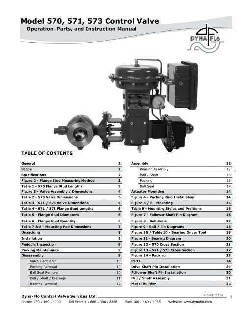
Model 570, 571, 573 Control Valve<br />
Operation, Parts, and Instruction Manual<br />
TABLE OF CONTENTS<br />
General 2 Assembly 12<br />
Scope 2 Bearing Assembly 12<br />
Specifications 2 Ball / Shaft 13<br />
Figure 2 - Flange Stud Measuring Method 3 Packing 13<br />
Table 1 - 570 Flange Stud Lengths 3 Ball Seal 14<br />
Figure 3 - Valve Assembly / Dimensions 4 Actuator Mounting 14<br />
Table 2 - 570 Valve Dimensions 5 Figure 4 - Packing Ring Installation 14<br />
Table 3 - 571 / 573 Valve Dimensions 5 Figure 5 / 6 - Mounting 15<br />
Table 4 - 571 / 573 Flange Stud Lengths 6 Table 9 - Mounting Styles and Positions 16<br />
Table 5 - Flange Stud Diameters 6 Figure 7 - Follower Shaft Pin Diagram 16<br />
Table 6 - Flange Stud Quantity 6 Figure 8 - Ball Seals 17<br />
Table 7 & 8 - Mounting Pad Dimensions 7 Figure 9 - Ball / Pin Diagrams 18<br />
Unpacking 8 Figure 10 / Table 10 - Bearing Driver Tool 19<br />
Installation 8 Figure 11 - Bearing Diagram 20<br />
Periodic Inspection 9 Figure 12 - 570 Cross Section 21<br />
Packing Maintenance 9 Figure 13 - 571 / 573 Cross Section 22<br />
Disassembly 9 Figure 14 - Packing 23<br />
Valve / Actuator 10 Parts 24<br />
Packing Removal 10 Drive Shaft Pin Installation 29<br />
Ball Seal Removal 10 Follower Shaft Pin Installation 30<br />
Ball / Shaft / Bearings 11 Ball / Shaft Assembly 31<br />
Bearing Removal 12 Model Builder 32<br />
Dyna-Flo Control Valve Services Ltd.<br />
Phone: 780 • 469 • 4000 Toll Free: 1 • 866 • 396 • 2356 Fax: 780 • 469 • 4035 Website: www.<strong>dyna</strong><strong>flo</strong>.com<br />
P-570M0115A<br />
1
Model 570, 571, 573 Control Valve<br />
Operation, Parts, and Instruction Manual<br />
NOTICE<br />
These <strong>instruction</strong>s are meant to be used with the Dyna-Flo 570 Series Technical Bulletin as they refer to<br />
Figures and Tables therein. If you do not have the Technical Bulletin, contact Dyna-Flo immediately,<br />
or visit www.<strong>dyna</strong><strong>flo</strong>.com<br />
Each <strong>control</strong> valve is factory checked. Check the calibration for the specific application, before a valve<br />
is put into service.<br />
It is the intention of this document to provide users with an accurate guide for safe installation and<br />
maintenance of the 570 Series Control Valves. Revisions and updates are available at above mentioned<br />
website.<br />
GENERAL<br />
The following <strong>instruction</strong>s are to be thoroughly re<strong>view</strong>ed and understood prior to installing, operating or performing<br />
maintenance on this equipment. Work on this equipment should be performed by experienced personnel. Throughout<br />
the <strong>manual</strong>, safety and caution notes appear and must be strictly followed, to prevent serious injury or equipment<br />
malfunction.<br />
SCOPE<br />
The <strong>control</strong> valve configuration and construction materials were selected to meet particular pressure, temperature, and process<br />
conditions. Some material combinations are limited in their pressure and temperature ranges. Do not apply any other conditions to<br />
the valve without first contacting your Dyna-Flo sales office.<br />
This <strong>manual</strong> is written to be a practical and useful guide maintaining the Dyna-Flo 570 Series Control Valve.<br />
CAUTION<br />
To avoid personal injury or installation damage as a result of the sudden release of process pressure or the breaking of<br />
parts, do not install the valve assembly where service conditions could exceed the limits stated in this <strong>manual</strong> or on<br />
the equipment nameplates. Use government codes, accepted industry standards and good piping practices to select<br />
pressure-relieving equipment for protection of your installation. It is also important to wear the proper<br />
protective equipment when performing any installation or maintenance activity.<br />
SPECIFICATIONS<br />
Maximum Pressure / Temperature Ratings<br />
Consistent with applicable pressure/temperature ratings per<br />
ASME B16.34-2004. See Table 14 & 15 of Sales Bulletin.<br />
Maximum Allowable Shutoff Pressure Drop<br />
See Table 15 of Sales Bulletin.<br />
750 psig (51.71 Bar) @ 100 o F (38 o C) (Standard Construction)<br />
Material Temperature Capabilities<br />
Standard: -50 o F to 450 o F (-46 o C to 232 o C) LCC.<br />
Optional: High Temp -20 o F to 800 o F (-29 o C to 427 o C) WCC.<br />
See Table 14 & 15 of Sales Bulletin.<br />
Construction Materials<br />
See Parts section for construction materials.<br />
Contact your Dyna-Flo sales office for more information and<br />
other options.<br />
Flow Direction<br />
Forward (through seal into ball).<br />
Actuator Mounting<br />
Right-hand, or Left-hand (as <strong>view</strong>ed from upstream side of<br />
valve). In one of 4 positions (12 (Std.), 3, 6, and 9 o’clock)<br />
with respect to the valve body in a horizontal pipe.<br />
See Figure 6.<br />
Dyna-Flo Control Valve Services Ltd.<br />
Phone: 780 • 469 • 4000 Toll Free: 1 • 866 • 396 • 2356 Fax: 780 • 469 • 4035 Website: www.<strong>dyna</strong><strong>flo</strong>.com<br />
P-570M0115A<br />
2
Model 570, 571, 573 Control Valve<br />
Operation, Parts, and Instruction Manual<br />
SPECIFICATIONS (Continued)<br />
Maximum Ball Rotation<br />
90 degrees.<br />
Shutoff Classification<br />
• Composition Ball Seal: Class VI<br />
• Metal Ball Seal: Class IV<br />
• Classes and testing per ASME/FCI 70-2<br />
Valve Dimensions<br />
See Figure 3 for valve diagram.<br />
See Tables 1 - 8 for valve dimensions.<br />
See Tables 1, 4, 5, and 6 for bolting dimensions.<br />
Actuator Sizing<br />
See Table 11 of Sales Bulletin.<br />
VALVE<br />
570<br />
(wafer*)<br />
ASME RATING<br />
CLASS<br />
150<br />
300<br />
600<br />
571 (flanged) 150<br />
573 (flanged) 300<br />
*NOTE - Wafer available in sizes 2 to 8 inch only.<br />
Valve and Actuator Assembly Weight<br />
See Table 13 of Sales Bulletin.<br />
Options<br />
Line Flange Bolting - Tables 1, 4, 5, and 6.<br />
Stainless Steel Construction.<br />
Internal Coatings.<br />
Shaft Connections.<br />
For more information and other options contact your Dyna-Flo<br />
sales office.<br />
Figure 2<br />
Flange Stud Measuring<br />
Method<br />
MEASURE FROM FIRST FULL THREAD TO<br />
FIRST FULL THREAD<br />
Model 570 Flange Stud Lengths - See Figure 2 & 3<br />
Table 1<br />
Valve Size<br />
(inches)<br />
I<br />
Class 150 Class 300 Class 600<br />
2 8.31 (211) 9.31 (237) 9.31 (237)<br />
3 10.00 (254) 11.00 (279) 11.25 (286)<br />
4 11.25 (286) 12.00 (305) 13.50 (343)<br />
6 13.50 (343) 14.25 (362) 16.25 (423)<br />
8 13.50 (343) 15.25 (387) 16.75 (426)<br />
Dyna-Flo Control Valve Services Ltd.<br />
Phone: 780 • 469 • 4000 Toll Free: 1 • 866 • 396 • 2356 Fax: 780 • 469 • 4035 Website: www.<strong>dyna</strong><strong>flo</strong>.com<br />
P-570M0115A<br />
3
Model 570, 571, 573 Control Valve<br />
Operation, Parts, and Instruction Manual<br />
G<br />
E<br />
Figure 3<br />
Typical Valve Assembly<br />
Diagram and Dimensions<br />
F<br />
C<br />
H<br />
D B A<br />
I<br />
MODEL 571 & 573<br />
Centering Studs<br />
MODEL 570<br />
K<br />
N<br />
A<br />
L<br />
O<br />
M<br />
M<br />
3” to<br />
12”<br />
VALVES<br />
2” VALVE<br />
N<br />
Dyna-Flo Control Valve Services Ltd.<br />
Phone: 780 • 469 • 4000 Toll Free: 1 • 866 • 396 • 2356 Fax: 780 • 469 • 4035 Website: www.<strong>dyna</strong><strong>flo</strong>.com<br />
P-570M0115A<br />
4
Model 570, 571, 573 Control Valve<br />
Operation, Parts, and Instruction Manual<br />
Model 570 Valve Dimensions Inch (mm)<br />
Table 2<br />
Valve /<br />
Actuator<br />
Size<br />
Dimensional Reference<br />
A B C D E F G H<br />
2” / DFR026 4.88 (124) 4.19 (106) 5.00 (127) 10.4 (264) 15.3 (389) 10.1 (257) 9.90 (251) 0.70 (17.8)<br />
3” / DFR047 6.50 (165) 4.62 (117) 5.12 (130) 11.4 (290) 17.1 (434) 13.3 (338) 11.4 (290) 1.31 (33.3)<br />
4” / DFR070 7.62 (194) 5.25 (133) 5.56 (141) 11.9 (302) 18.4 (467) 23.9 (607) 13.1 (333) 2.12 (53.8)<br />
6” / DFR156 9.00 (229) 6.25 (159) 7.06 (179) 13.4 (340) 21.8 (548) 34.5 (876) 18.6 (472) 2.50 (63.5)<br />
8” / DFR156 9.56 (243) 7.69 (195) 9.12 (232) 14.9 (378) 24.2 (615) 34.5 (876) 18.6 (472) 2.50 (63.5)<br />
8” / DFR220 9.56 (243) 7.69 (195) 9.12 (232) 14.9 (378) 25.5 (648) 33.4 (848) 21.1 (536) 2.50 (63.5)<br />
ASME Class: 150 / 300 / 600<br />
• Envelope Dimensions are + / - 0.25 in. (6.4 mm)<br />
• Face to Face Tolerance Per ASME<br />
Model 571 and 573 Valve Dimensions Inch (mm)<br />
Table 3<br />
Valve /<br />
Actuator<br />
Size<br />
Dimensional Reference<br />
A B C D E F G H<br />
2” / DFR026 4.88 (124) 4.19 (106) 5.00 (127) 10.4 (264) 15.3 (389) 10.1 (257) 9.90 (251) 0.70 (17.8)<br />
3” / DFR047 6.50 (165) 4.62 (117) 5.12 (130) 11.4 (290) 17.1 (434) 13.3 (338) 11.4 (290) 1.31 (33.3)<br />
4” / DFR070 7.62 (194) 5.25 (133) 5.56 (141) 11.9 (302) 18.4 (467) 23.9 (607) 13.1 (333) 2.12 (53.8)<br />
6” / DFR156 9.00 (229) 6.25 (159) 7.06 (179) 13.4 (340) 21.8 (548) 34.5 (876) 18.6 (472) 2.50 (63.5)<br />
8” / DFR156 9.56 (243) 7.69 (195) 9.12 (232) 14.9 (378) 24.2 (615) 34.5 (876) 18.6 (472) 2.50 (63.5)<br />
8” / DFR220 9.56 (243) 7.69 (195) 9.12 (232) 14.9 (378) 25.5 (648) 33.4 (848) 21.1 (536) 2.50 (63.5)<br />
10” / DFR220 11.69 (297) 8.75 (222) 10.25 (260) 16.1 (409) 26.7 (678) 33.4 (848) 21.1 (536) 2.50 (63.5)<br />
12” / DFR220 13.31 (338) 10.56 (268) 11.94 (303) 17.74 (451) 28.29 (719) 33.4 (848) 21.1 (536) 2.50 (63.5)<br />
ASME Class: 571 = 150, 573 = 300<br />
• Envelope Dimensions are + / - 0.25 in. (6.4 mm)<br />
• Face to Face Tolerance Per ASME<br />
Dyna-Flo Control Valve Services Ltd.<br />
Phone: 780 • 469 • 4000 Toll Free: 1 • 866 • 396 • 2356 Fax: 780 • 469 • 4035 Website: www.<strong>dyna</strong><strong>flo</strong>.com<br />
P-570M0115A<br />
5
Model 570, 571, 573 Control Valve<br />
Operation, Parts, and Instruction Manual<br />
Model 571 and 573 Flange Stud Lengths Inch (mm)<br />
See Figure 2 & 3<br />
Table 4<br />
Valve Size<br />
Inch<br />
571 573<br />
K L K L<br />
2 3.61 (92) 4.11 (104) 3.86 (98) 4.11 (104)<br />
3 3.86 (98) 4.11 (104) 4.65 (118) 5.15 (131)<br />
4 3.86 (98) 4.61 (117) 4.90 (124) 5.40 (137)<br />
6 4.40 (112) 4.90 (124) 5.40 (137) 5.90 (150)<br />
8 4.90 (124) 5.15 (131) 5.94 (151) 6.44 (164)<br />
10 5.19 (132) 5.69 (145) 6.75 (171) 7.25 (184)<br />
12 5.19 (132) 5.94 (151) 7.25 (184) 7.75 (197)<br />
Flange Stud Diameters and Threads Per Inch (TPI)<br />
Table 5<br />
Valve Size<br />
Inch<br />
Stud Diameter Inch (mm)<br />
Class 150 Class 300 Class 600 Class 150 Class 300 Class 600<br />
2 5/8 (15.7) 5/8 (15.7) 5/8 (15.7) 11 11 11<br />
3 5/8 (15.7) 3/4 (19.1) 3/4 (19.1) 11 10 10<br />
4 5/8 (15.7) 3/4 (19.1) 7/8 (22.2) 11 10 9<br />
6 3/4 (19.1) 3/4 (19.1) 1 (25.4) 10 10 8<br />
8 3/4 (19.1) 7/8 (22.2) 1-1/8 (28.6) 10 9 7<br />
10 7/8 (22.2) 1 (25.4) 1-1/4 (31.8) 9 8 7<br />
12 7/8 (22.2) 1-1/8 (28.6) 1-1/4 (31.8) 9 7 7<br />
TPI<br />
Flange Stud Quantity<br />
Table 6<br />
Valve Size<br />
Inch<br />
Number of Studs Required (Double for Models 571 & 573)<br />
Class 150 Class 300 Class 600<br />
2 4 8 8<br />
3 4 8 8<br />
4 8 8 8<br />
6 8 12 12<br />
8 8 12 12<br />
10 12 16 16<br />
12 12 16 20<br />
Dyna-Flo Control Valve Services Ltd.<br />
Phone: 780 • 469 • 4000 Toll Free: 1 • 866 • 396 • 2356 Fax: 780 • 469 • 4035 Website: www.<strong>dyna</strong><strong>flo</strong>.com<br />
P-570M0115A<br />
6
Model 570, 571, 573 Control Valve<br />
Operation, Parts, and Instruction Manual<br />
Model 570 Valve Mounting Pad Dimensions Inch (mm)<br />
Table 7<br />
Valve<br />
Inch<br />
Dimensional Reference<br />
N M O<br />
2 0.56 (14.2) 4.62 (117) —<br />
3 0.56 (14.2) 6.00 (152) 1.25 (31.8)<br />
4 0.56 (14.2) 6.00 (152) 1.25 (31.8)<br />
6 0.56 (14.2) 6.00 (152) 1.25 (31.8)<br />
8 0.69 (17.5) 9.25 (235) 1.81 (46.0)<br />
Model 571 & 573 Valve Mounting Pad Dimensions Inch (mm)<br />
Table 8<br />
Valve<br />
Inch<br />
Dimensional Reference<br />
N M O<br />
2 0.56 (14.2) 4.62 (117) —<br />
3 0.56 (14.2) 6.00 (152) 1.25 (31.8)<br />
4 0.56 (14.2) 6.00 (152) 1.25 (31.8)<br />
6 0.56 (14.2) 6.00 (152) 1.25 (31.8)<br />
8 0.69 (17.5) 9.25 (235) 1.81 (46.0)<br />
10 0.69 (17.5) 9.25 (235) 1.81 (46.0)<br />
12 0.69 (17.5) 9.25 (235) 1.81 (46.0)<br />
Our Commitment to Quality<br />
Dyna-Flo is committed to continuous improvement. While all efforts have been made to ensure the accuracy of the content in<br />
this document, modifications or improvements to the information, specifications, and designs may occur at any time without<br />
notice. This document was published for informational purposes only, and does not express or imply suitability, a warranty,<br />
or guarantee regarding the products or services described herein or their use or applicability.<br />
Neither Dyna-Flo Control Valve Services Ltd., nor any of their affiliated entities assumes responsibility for the selection, use<br />
and maintenance of any product. Responsibility for selection, use and maintenance of any product remains with the purchaser<br />
and end-user.<br />
Dyna-Flo Control Valve Services Ltd.<br />
Phone: 780 • 469 • 4000 Toll Free: 1 • 866 • 396 • 2356 Fax: 780 • 469 • 4035 Website: www.<strong>dyna</strong><strong>flo</strong>.com<br />
P-570M0115A<br />
7
Model 570, 571, 573 Control Valve<br />
Operation, Parts, and Instruction Manual<br />
UNPACKING VALVE FROM SHIPPING<br />
CONTAINER<br />
Check the packing list against materials received, while<br />
unpacking the valve. The Packing List describes valve and<br />
accessories in each shipping container.<br />
When preparing <strong>valves</strong> and actuators for lifting, be sure to use<br />
certified lifting equipment and proper rigging. Position any<br />
lifting straps to avoid damage to the tubing and mounted<br />
accessories.<br />
INSTALLATION<br />
WARNING<br />
Refer to the General and Scope sections of this<br />
Manual (See Page 2) prior to beginning Installation.<br />
Before installing these <strong>valves</strong>, be sure to inspect the flange<br />
mating surfaces on both the valve and the pipeline flanges.<br />
Clean dirt, welding chips, scale or other foreign material from<br />
the line and flange surfaces. Check the pipeline flanges for<br />
alignment and look for signs of gasket leakage through the line<br />
flanges, make repairs if necessary.<br />
The Model 570 requires the use of long studs that span the<br />
length of the valve and through both line flanges. The body<br />
casting is designed to utilize the long studs to assist in<br />
centering the valve in the line. Models 571 & 573 use shorter<br />
studs to connect the valve flanges with the line flanges,<br />
the studs do not center the valve in the pipeline.<br />
CAUTION<br />
Only well trained experienced technicians should<br />
perform these procedures. Be sure to use safe work<br />
practices and lockout procedures. Always be aware<br />
of the hazards of spring-loaded actuators. Be sure<br />
that they are in the failed (de-energized) position<br />
before performing any maintenance procedure.<br />
These <strong>valves</strong> have dangerous pinch points. Never<br />
put your hands inside the valve unless you are<br />
certain that the ball cannot rotate. Use safe work<br />
practices and lock out procedures when isolating<br />
<strong>valves</strong> and actuators. Always be aware of flammable<br />
instrument gas.<br />
1 Install the valve with <strong>flo</strong>w through the valve in the direction<br />
as indicated by the arrow on the valve body (standard <strong>flo</strong>w<br />
direction has the seal protector ring (Key 10) facing<br />
upstream). The valve assembly may be installed in any<br />
position unless limited by vibration considerations, See<br />
Figure 6. NOTE: excessive wear to the valve may be<br />
caused if the valve is installed with the drive shaft<br />
(Key 16) in a vertical orientation.<br />
WARNING<br />
Keep hands, hair and clothing away from all moving<br />
parts when operating the valve. Serious injury can<br />
result from failure to do so.<br />
Model 570 Installation<br />
(Refer to Figures 2 and 3, and Tables 1, 4, 5, and 6 for<br />
flange stud (Key 32) dimensions)<br />
1 Coat the threads of two flange studs with anti-seize<br />
lubricant and install them into the flanges before<br />
placing the valve body. The two studs should be placed<br />
appropriately to help center the bottom of the valve<br />
body, See Figure 3.<br />
2 Set the appropriate line gaskets in place.<br />
3 Insert the valve into line centering the bottom of the<br />
valve body between the two studs installed in Step 1.<br />
Lubricate the remaining studs with anti-seize<br />
compound and install them. Make sure the valve<br />
is properly centered between the pipeline flanges and<br />
then tighten the flange studs evenly in a criss-cross<br />
pattern to the correct torque specifications.<br />
Models 571 & 573 Installation<br />
(Refer to Figures 2 and 3, and Tables 1, 4, 5, and 6 for<br />
flange stud (Key 32) dimensions)<br />
NOTE<br />
Longer flange studs are needed for the seal<br />
protector ring (Key 10) side of the valve. DO NOT<br />
use standard length studs for the seal protector<br />
side of the valve, see Table 4.<br />
1 Lubricate the flange studs with anti-seize compound<br />
and have them ready to hold the valve in line.<br />
2 Set the appropriate line gaskets in place.<br />
Dyna-Flo Control Valve Services Ltd.<br />
Phone: 780 • 469 • 4000 Toll Free: 1 • 866 • 396 • 2356 Fax: 780 • 469 • 4035 Website: www.<strong>dyna</strong><strong>flo</strong>.com<br />
P-570M0115A<br />
8
Model 570, 571, 573 Control Valve<br />
Operation, Parts, and Instruction Manual<br />
INSTALLATION (Continued)<br />
Models 571 & 573 Installation (Continued)<br />
3 Insert the valve in line and make sure the valve is<br />
properly centered between the pipeline flanges.<br />
Tighten all the flange studs and nuts evenly in a crisscross<br />
pattern to the correct torque specifications.<br />
Air Piping<br />
Standard actuators are designed to accept a 1/4” (6 mm) NPT<br />
connection. Use 3/8” OD tubing (or equivalent) for all air<br />
lines. Always follow good piping practices when installing<br />
piping or tubing, install all required line vents, <strong>valves</strong>,<br />
drains, seals, and filters. For more information refer to the<br />
appropriate actuator <strong>instruction</strong> <strong>manual</strong> for your product.<br />
WARNING<br />
Property damage, environmental harm, and<br />
personal injury can result from the use of supply<br />
gas other than clean, non-corrosive, oil and<br />
moisture free air. Do not exceed the supply<br />
pressure indicated on the serial plate located on<br />
the yoke of the actuator.<br />
PERIODIC INSPECTION<br />
CAUTION<br />
Use safe work practices and lock out procedures<br />
when isolating <strong>valves</strong> and actuators! Always be<br />
aware of flammable instrument gas!<br />
1 Avoid personal injury from sudden release of process<br />
pressure! Before performing any maintenance operation:<br />
A<br />
Disconnect any power supply media lines providing<br />
air / gas pressure, electric power, or a <strong>control</strong> signal<br />
to the actuator. Ensure the actuator cannot suddenly<br />
operate the valve.<br />
2 Check for process fluid leakage to the atmosphere through<br />
the packing and (if equipped) any NPT connection.<br />
3 Examine the valve for damage caused by corrosive fumes<br />
or process drippings.<br />
4 Clean the valve and repaint areas of severe oxidation.<br />
6 Ensure all accessories, mounting brackets and fasteners<br />
are secure.<br />
7 Clean any dirt and foreign material from the stem.<br />
PACKING MAINTENANCE<br />
If the packing is leaking, and tightening the packing flange<br />
does not stop the leak, then it is recommended that you<br />
remove the valve from the line. Refer to Valve Disassembly /<br />
Packing Removal for maintenance <strong>instruction</strong>s. For live loaded<br />
packing, refer to the live loaded packing <strong>instruction</strong>s for proper<br />
adjustment procedures.<br />
DISASSEMBLY<br />
CAUTION<br />
Only well trained experienced technicians should<br />
perform these procedures. Be sure to use safe work<br />
practices and lockout procedures. Always be aware<br />
of the hazards of spring-loaded actuators. Be sure<br />
that they are in the failed (de-energized) position<br />
before performing any maintenance procedure.<br />
These <strong>valves</strong> have dangerous pinch points.<br />
Never put your hands inside the valve unless<br />
you are certain that the ball cannot rotate.<br />
1 Isolate the valve from the process by completely<br />
shutting off the process pressure or use bypass <strong>valves</strong> if<br />
necessary. Drain the process fluid from upstream and<br />
downstream of the valve.<br />
B<br />
C<br />
D<br />
Isolate the valve from process pressure with bypass<br />
<strong>valves</strong> or completely shut off the process. Relieve<br />
process pressure, and drain the process fluid from<br />
the up and down stream of the valve.<br />
Vent the pneumatic actuator loading pressure and<br />
relieve any actuator spring preload.<br />
Use Safety lock-out procedures to be sure that the<br />
above provisions stay in effect while you complete<br />
the work on your equipment.<br />
2 Disconnect any power supply media lines providing air /<br />
gas pressure, electric power, or a <strong>control</strong> signal to the<br />
actuator. Isolate and bleed off any instrument gas from<br />
the actuator and instruments. Ensure the actuator cannot<br />
suddenly operate the valve.<br />
CAUTION<br />
Use safe work practices and lock out procedures<br />
when isolating <strong>valves</strong> and actuators! Always be<br />
aware of flammable instrument gas!<br />
Dyna-Flo Control Valve Services Ltd.<br />
Phone: 780 • 469 • 4000 Toll Free: 1 • 866 • 396 • 2356 Fax: 780 • 469 • 4035 Website: www.<strong>dyna</strong><strong>flo</strong>.com<br />
P-570M0115A<br />
9
Model 570, 571, 573 Control Valve<br />
Operation, Parts, and Instruction Manual<br />
DISASSEMBLY (Continued)<br />
3 Secure the valve and actuator assembly and remove them<br />
from the pipeline by removing the flange studs (Key 32).<br />
Valve / Actuator Disassembly<br />
1 Replacing the ball seal can be accomplished without<br />
removing the actuator. Place the valve assembly on a<br />
flat work surface that can support the assembly<br />
weight, the valve seal protector ring (Key 10) should<br />
be facing up. Relieve any actuator spring preload and<br />
refer to the appropriate actuator <strong>instruction</strong> <strong>manual</strong><br />
for actuator disassembly <strong>instruction</strong>s.<br />
2 Take note of the ball position relative to the<br />
actuator lever where the spline of the shaft goes<br />
through. This will assure proper ball position during<br />
reassembly. A digital camera works well for this. You<br />
can remove the travel indicator arrow, (DFR 026 and<br />
DFR 047) or the cover plate, (DFR 070, DFR 156 and<br />
DFR 220) from the actuator and mark the shaft and<br />
lever with a punch or take a digital picture showing<br />
the ball position and the lever position. For Dyna-Flo<br />
Model DFR 026 actuators there is no clamp on the<br />
lever. For the DFR 047, DFR 070, DFR 156 and the DFR<br />
220 you will have to remove the cover and loosen the<br />
clamp on the lever.<br />
3 Remove the actuator mounting bolt (Key 30) and slide<br />
the valve body assembly from the actuator. This may<br />
require the use of a pry bar between the body and the<br />
actuator mounting pad. The lever on the DFR 070, DFR<br />
156 and DFR 220 will sometimes bind when trying to<br />
remove the valve body assembly. A wedge driven into<br />
the slot in the lever will help to loosen the clamp on<br />
the lever. CAUTION: Using a hammer to drive the<br />
actuator off of the valve shaft can seriously damage<br />
the valve.<br />
1 Remove the packing nuts (Key 27), note any corrosion<br />
or roughness in the threads. Remove the packing<br />
follower (Key 23) by sliding it over the drive shaft<br />
(Key 16). NOTE: packing followers can be 1 piece or<br />
two piece design depending on construction material.<br />
NOTE<br />
Valve shaft packing (Key 22) may be removed<br />
without removing the drive shaft (Key 16) from<br />
the valve however it is easier to remove the<br />
packing and inspect the valve shaft and packing<br />
bore when the drive shaft is removed. Refer to<br />
Ball / Shaft Removal for drive shaft disassembly<br />
<strong>instruction</strong>s.<br />
2 Using a mechanics pick set or wire hook, remove the<br />
packing (Keys 21 & 22) from the packing bore. Be<br />
extremely cautious not to damage the drive shaft<br />
or the packing bore while removing packing as this will<br />
cause new packing to leak.<br />
3 Inspect all packing parts, drive shaft, and packing bore<br />
for damage, polish or replace as necessary. Refer to<br />
Assembly / Packing for packing assembly <strong>instruction</strong>s.<br />
Ball Seal Removal<br />
NOTE<br />
During seal removal, the valve actuator may<br />
remain mounted to the valve body.<br />
1 Rotate the valve ball (Key 3) to the open position.<br />
For PTFE Composition Ball Seals<br />
A Remove the seal protector ring screws (Key 12)<br />
and seal protector clips (Key 11). Carefully<br />
remove the seal protector ring (Key 10) and<br />
gasket (Key 9).<br />
WARNING<br />
To Avoid personal injury and property damage<br />
use caution when separating the actuator from<br />
the valve body, during removal the valve ball<br />
may rotate in the body.<br />
Packing Removal<br />
For live loaded packing, refer to the Live Loaded Packing<br />
<strong>instruction</strong> <strong>manual</strong> (P-LLPR) for assembly <strong>instruction</strong>s.<br />
B<br />
C<br />
Remove the seal (Key 5) from the valve body.<br />
For 2 inch <strong>valves</strong> remove the back-up ring<br />
(Key 4) as well.<br />
Clean and inspect all seating, sealing, and gasket<br />
surfaces for damage. If there is excessive wear<br />
or damage to the seal ring, check the valve ball<br />
(Key 3) for damage in corresponding areas. It is<br />
also a good opportunity to inspect the flange<br />
gasket surfaces for damage while the valve is<br />
out of line.<br />
Dyna-Flo Control Valve Services Ltd.<br />
Phone: 780 • 469 • 4000 Toll Free: 1 • 866 • 396 • 2356 Fax: 780 • 469 • 4035 Website: www.<strong>dyna</strong><strong>flo</strong>.com<br />
P-570M0115A<br />
10
Model 570, 571, 573 Control Valve<br />
Operation, Parts, and Instruction Manual<br />
DISASSEMBLY (Continued)<br />
Ball Seal Removal (Continued)<br />
For Metal Ball Seals<br />
A Remove the seal protector ring screws (Key 12)<br />
and seal protector clips (Key 11). Carefully<br />
remove the seal protector ring (Key 10) and<br />
gasket (Key 9). NOTE: Caution when<br />
removing the seal protector ring the metal ball<br />
seal can fall out and damage itself or the ball.<br />
B<br />
C<br />
D<br />
Carefully remove the metal ball seal (Key 6) by<br />
pushing it away from the flange gasket side of the<br />
seal protector ring.<br />
Remove the wave spring (Key 8) and the radial<br />
seal (Key 7) from the seal protector ring.<br />
Clean and inspect all seating, sealing, and gasket<br />
surfaces for damage. It is also a good<br />
opportunity to inspect the flange gasket surfaces<br />
for damage while the valve is out of line.<br />
Ball / Shaft and Bearing Removal<br />
CAUTION<br />
If the bearings (Key 20) require removal special<br />
tooling may be required. In most cases the bearings<br />
can be removed with a standard punch, a standard<br />
punch may also damage the bearings. If the bearings<br />
are to be reused, see Table 7 for drawings and<br />
information on bearing removal tools that will not<br />
damage the bearings.<br />
NOTE<br />
Before the bearings can be removed from the valve<br />
both the drive shaft (Key 16) and follower shaft<br />
(Key 13) must be removed from the valve body<br />
(Key 1). The ball seals must be removed prior to<br />
removing the valve ball and valve shafts.<br />
The follower shaft to ball connection uses a follower shaft pin<br />
(key 14) in a stepped hole and can only be installed and<br />
removed in one direction. (See Figure 9)<br />
For 3 through 12 inch <strong>valves</strong> the valve shaft / valve ball<br />
connection is made using a shaft key (Key 18), see Figure 8.<br />
The shaft / ball connection is factory set, but if the shaft or key<br />
needs to be replaced or if the connection is loose it will need to<br />
be reset. Refer to the Assembly <strong>instruction</strong>s.<br />
Always use caution and protect the flange gasket surfaces from<br />
damage during disassembly.<br />
For 2 Inch Valves<br />
1 Mark the shaft to show the orientation of the ball<br />
before beginning disassembly, this will help to<br />
re-install the shaft properly on reassembly. It is<br />
possible to install the valve shaft 180 degrees out of<br />
alignment which will make it difficult to mount the<br />
actuator.<br />
2 Rotate the ball to the ‘open’ position and locate the<br />
smaller of the pin holes on the ball (see Figure 8).<br />
To keep the ball and shaft in proper position it may<br />
be necessary to support the ball using a wood or soft<br />
block during disassembly. Using a 3/16” pin punch,<br />
drive the shaft pin (Key 15) out of the ball / drive shaft<br />
(Key 16) connection by driving the shaft pin out the<br />
larger side of the pin hole.<br />
3 Using the same 3/16” pin punch, remove the follower<br />
shaft pin (Key 14) from the valve ball / follower shaft<br />
(Key 13) connection.<br />
4 Remove the pipe plug (Key 28) and drive the follower<br />
shaft into the ball towards the drive shaft. If the drive<br />
shaft cannot be pulled out by hand, continue to drive<br />
the follower shaft into the drive shaft until it loosens.<br />
Being careful not to allow the ball to drop, pull the<br />
drive shaft from the valve body through the actuator<br />
mounting end of the valve.<br />
5 Remove and inspect the valve ball for damage. Inspect<br />
the valve shafts and valve body for damage as well.<br />
For 3 through 12 Inch Valves<br />
1 Mark the shaft to show the orientation of the ball<br />
before beginning disassembly, this will help to<br />
re-install the shaft properly on reassembly. It is<br />
possible to install the valve shaft 180 degrees out of<br />
alignment which will make it difficult to mount the<br />
actuator.<br />
2 Rotate the ball to the ‘open’ position and locate the<br />
smaller end of the keyhole on the valve ball / drive<br />
shaft (Key 16) connection. To keep the ball and shaft<br />
in proper position it may be necessary to support the<br />
ball using a wood or soft block during disassembly.<br />
Dyna-Flo Control Valve Services Ltd.<br />
Phone: 780 • 469 • 4000 Toll Free: 1 • 866 • 396 • 2356 Fax: 780 • 469 • 4035 Website: www.<strong>dyna</strong><strong>flo</strong>.com<br />
P-570M0115A<br />
11
Model 570, 571, 573 Control Valve<br />
Operation, Parts, and Instruction Manual<br />
DISASSEMBLY (Continued)<br />
Ball / Shaft and Bearing Removal (Continued)<br />
For 3 through 12 Inch Valves (Continued)<br />
3 Using an appropriately sized pin punch, drive the key<br />
(Key 18) out of the ball / drive shaft connection by<br />
driving through the smaller of the keyholes pushing<br />
the key away. See Figure 8.<br />
4 Using the a 3/16” pin punch, remove the follower shaft<br />
pin (Key 14) from the valve ball / follower shaft (Key<br />
13) connection. Be sure to check the ball / follower<br />
shaft connection for a stepped hole, always drive the<br />
follower shaft pin from the smaller hole out the larger.<br />
5 Remove the pipe plug (Key 28) and drive the follower<br />
shaft inward towards the drive shaft. If the drive<br />
shaft cannot be pulled out by hand, continue to drive<br />
the follower shaft into the drive shaft until it loosens.<br />
Be very careful not to allow the ball to drop<br />
especially with larger <strong>valves</strong>! Pull the drive shaft<br />
from the valve body through the actuator mounting<br />
end of the valve.<br />
6 Remove and inspect the valve ball for damage. Inspect<br />
the valve shafts and valve body for damage as well.<br />
Bearing Removal<br />
NOTE<br />
If the bearings (Key 20) need to be replaced, please<br />
note that Dyna-Flo bearing configurations have<br />
changed for 570 series <strong>control</strong> <strong>valves</strong> and new<br />
replacement bearing kits will reflect this change.<br />
2 Remove the bearings by hand. If the bearings are<br />
unable to be removed by hand refer to Table 7 for<br />
bearing removal tool dimensions and <strong>instruction</strong>s.<br />
CAUTION: If the bearings require removal special<br />
tooling may be required. In most cases the bearings<br />
can be removed with a standard punch, a standard<br />
punch may also damage the bearings.<br />
3 Remove and replace the thrust washer (Key 19) if<br />
required.<br />
4 Inspect internal surfaces for evidence of wear and<br />
repair if required.<br />
ASSEMBLY<br />
Ensure that all parts have been thoroughly cleaned and<br />
inspected as per disassembly section prior to assembly.<br />
Replace damaged parts and always replace packing and<br />
gaskets.<br />
Bearing Assembly<br />
NOTE<br />
If the bearings (Key 20) need to be replaced, please<br />
note that Dyna-Flo bearing configurations have<br />
changed for 570 series <strong>control</strong> <strong>valves</strong> and new<br />
replacement bearing kits will reflect this change.<br />
Valve sizes 6, 8, 10, and 12 inch use specific inboard<br />
and outboard bearings. Pay close attention when<br />
ordering parts and assembling these sizes. All other<br />
sizes use identical inboard /outboard bearings.<br />
Inboard and outboard bearings are only present for valve sizes<br />
6” through 12” with S17400 bearing material. All other bearing<br />
combinations and sizes utilize two identical bearings.<br />
Thrust washers (Key 19) are only required for <strong>valves</strong> sizes 6”<br />
through 12” with S17400 bearing material. All other bearing<br />
combinations and sizes no longer require a thrust washer.<br />
1 Inspect the bearings, remove the bearings only if they<br />
are damaged and require removal.<br />
Thrust washers (Key 19) are only required for <strong>valves</strong> sizes 6”<br />
through 12” with S17400 bearing material. All other bearing<br />
combinations and sizes no longer require a thrust washer.<br />
1 See Figure 11 to determine placement of inboard and<br />
outboard bearings if they are used. Install the bearings<br />
appropriately by hand or by using the appropriate bearing<br />
tool as indicated in Table 7. The flange of the bearing<br />
should be in contact with the valve body.<br />
Dyna-Flo Control Valve Services Ltd.<br />
Phone: 780 • 469 • 4000 Toll Free: 1 • 866 • 396 • 2356 Fax: 780 • 469 • 4035 Website: www.<strong>dyna</strong><strong>flo</strong>.com<br />
P-570M0115A<br />
12
Model 570, 571, 573 Control Valve<br />
Operation, Parts, and Instruction Manual<br />
ASSEMBLY (Continued)<br />
Ball / Shaft Assembly<br />
CAUTION<br />
To avoid dropping and damaging the valve ball<br />
(Key 3) when inserting the ball into the valve body<br />
(Key 1) it may be necessary to support the ball<br />
using a wood or soft block during assembly.<br />
NOTE<br />
For 3 through 12 inch <strong>valves</strong> the valve shaft / valve<br />
ball connection is made using a flat key (Key 18)<br />
and set screws (Key 17), see Figure 8. The shaft<br />
/ ball connection is factory set, but if the shaft or key<br />
needs to be replaced or if the connection is loose it<br />
will need to be reset prior to assembly. See Page 28.<br />
1 For valve sizes 3 through 12, set the drive shaft to ball<br />
connection prior to assembly. Refer to Page 28 for<br />
<strong>instruction</strong>s to set the shaft / ball connection.<br />
2 Carefully insert the valve ball into the valve body.<br />
Insert the follower shaft (Key 13) through the valve<br />
body and into the valve ball.<br />
3 Align the pin hole of the follower shaft with the follower<br />
shaft pin hole on the valve ball. Insert the groove pin<br />
(Key 14) into the ball / follower shaft assembly.<br />
4 Install the drive shaft (Key 16) through the bearing<br />
and into the valve ball. Set the valve shaft to the<br />
original orientation as per Step 1 of Ball / Shaft and<br />
Bearing Removal. Install the shaft key (Key 18) or<br />
shaft pin (Key 15) for 2” <strong>valves</strong>, and refer to Pages<br />
28, 29, and 30 for shaft pin and shaft key installation<br />
<strong>instruction</strong>s.<br />
5 With the follower shaft pins and flat key installed<br />
beneath the hole on the surface of the ball ear, stake<br />
the pins and/or flat key on both the drive shaft and<br />
follower shaft using a center punch. See Pages 28 - 30<br />
for further <strong>instruction</strong>s.<br />
Packing Installation<br />
1 Ensure all parts have been cleaned and inspected prior<br />
to replacing the packing. Refer to the Disassembly<br />
section for inspection procedures. For Live Loaded<br />
packing refer to the Live Loaded Packing <strong>instruction</strong><br />
<strong>manual</strong> for rotary <strong>valves</strong> (P-LLPR).<br />
NOTE<br />
To prevent trapping air when installing packing<br />
rings it is recommended that packing rings be<br />
installed one at a time. Do not force packing<br />
rings below the chamfer of the packing bore<br />
before adding another ring. See Figure 4.<br />
2 Install the packing parts as shown in Figure 14. For<br />
PTFE packing, lubricate the packing with a siliconebased<br />
lubricant.<br />
3 Install the packing follower (Key 23). NOTE: Packing<br />
followers constructed using special material may be a<br />
2 piece design.<br />
4 Thread the packing nuts (Key 27) onto the packing<br />
studs (Key 26) and tighten them in an alternating<br />
pattern until the packing follower is secured. The<br />
packing nuts should be tightened enough to stop<br />
leakage under operating conditions.<br />
Ball Seal Assembly<br />
1 Have all parts and seal surfaces cleaned and inspected<br />
prior to assembly. Refer to Disassembly section for<br />
inspection procedures.<br />
2 Rotate the ball (Key 3) to the closed position. Inspect<br />
the position of the ball along the axis of the shaft<br />
(Key 16). TThe ball should be no more than 0.005<br />
inches (0.13 mm) off the center line. It may be<br />
necessary to use a feeler gauge between the<br />
clearance angles just below where the ball seal sits,<br />
using a feeler gage the maximum difference would be<br />
0.010 inches (0.254 mm). For 2 inch <strong>valves</strong> the<br />
back-up ring (Key 4) will need to be installed to check<br />
the position of the ball. If the ball is not centered it<br />
may be due to some wear on the ears of the ball or<br />
the thrust face of the bearings, re-inspect all surfaces<br />
for damage.<br />
For PTFE Composition Ball Seals<br />
A<br />
B<br />
Install the ball seal (Key 5), gasket (Key 9) and<br />
seal protector ring (Key 10).<br />
Install the seal protector clips (Key 11) and seal<br />
protector ring screws (Key 12), tighten them<br />
completely in an alternating pattern.<br />
Dyna-Flo Control Valve Services Ltd.<br />
Phone: 780 • 469 • 4000 Toll Free: 1 • 866 • 396 • 2356 Fax: 780 • 469 • 4035 Website: www.<strong>dyna</strong><strong>flo</strong>.com<br />
P-570M0115A<br />
13
Model 570, 571, 573 Control Valve<br />
Operation, Parts, and Instruction Manual<br />
ASSEMBLY (Continued)<br />
Ball Seal Assembly (Continued)<br />
5 Re-install the actuator cover plate and travel indicator<br />
arrow.<br />
For Metal Ball Seals<br />
A<br />
B<br />
C<br />
D<br />
Lubricate the radial seal (Key 7) with white<br />
petroleum grease and install it into the groove in<br />
the seal protector ring (Key 10).<br />
Install the wave spring (Key 8) into the seal<br />
protector ring.<br />
Insert the metal seal (Key 6) into the seal<br />
protector ring, take extra care not to damage the<br />
radial seal when inserting the metal seal. Try to<br />
keep the metal seal ring from binding as you insert<br />
it by keeping it even and parallel.<br />
Install the gasket (Key 9), then install the metal<br />
seal / protector ring assembly over the gasket.<br />
Figure 4 Packing Ring Installation<br />
E<br />
Install the seal protector clips (Key 11) and seal<br />
protector ring screws (Key 12), tighten them<br />
completely in an alternating pattern.<br />
16<br />
ACTUATOR MOUNTING<br />
Refer to the appropriate actuator <strong>instruction</strong> <strong>manual</strong> for<br />
additional mounting <strong>instruction</strong>s. For mounting and fail position<br />
orientations see Figures 5 & 6.<br />
1 Set the valve to the desired fail position.<br />
23<br />
top of packing ring<br />
pushed down to be<br />
even with bottom of<br />
packing bore chamfer<br />
2 Clean the splines of the drive shaft and using the marks<br />
made in Step 2 of Valve / Actuator Disassembly insert<br />
the drive shaft (Key 16) into the actuator lever.<br />
1<br />
installing first<br />
packing ring<br />
3 Adjust the position of the valve, lever, and actuator so<br />
that the lever is centered and the actuator shaft is<br />
vertically parallel within the actuator housing. The lever<br />
should be able to move within the housing freely and<br />
unobstructed. Tighten the lever clamp to the drive shaft.<br />
4 Insert the actuator mounting bolt (Key 30) and bolt<br />
the valve and actuator together using the actuator<br />
mounting nuts (Key 31). Once the mounting bolts are<br />
tight, the valve may need to be readjusted in order<br />
to center the valve ball. Refer to the appropriate<br />
actuator <strong>instruction</strong> <strong>manual</strong> for information on<br />
adjusting the actuator turnbuckle to re-center<br />
the ball.<br />
top of packing ring<br />
pushed down to be<br />
even with bottom of<br />
packing bore chamfer<br />
installing second<br />
packing ring<br />
Dyna-Flo Control Valve Services Ltd.<br />
Phone: 780 • 469 • 4000 Toll Free: 1 • 866 • 396 • 2356 Fax: 780 • 469 • 4035 Website: www.<strong>dyna</strong><strong>flo</strong>.com<br />
P-570M0115A<br />
14
Model 570, 571, 573 Control Valve<br />
Operation, Parts, and Instruction Manual<br />
C<br />
D<br />
Left Hand Mount<br />
Figure 5 Mounting Orientation Diagram<br />
A<br />
B<br />
Right Hand Mount<br />
Figure 6 Actuator/Valve Position Chart<br />
ACTUATOR<br />
(diagrams shown using DFR model actuators)<br />
VALVE OPEN<br />
RIGHT-HAND MOUNTED ACTUATOR<br />
STYLE A<br />
PUSH DOWN TO CLOSE<br />
(PDTC)<br />
STYLE B<br />
PUSH DOWN TO OPEN<br />
(PDTO)<br />
ACTUATOR POSITIONS<br />
ACTUATOR POSITIONS<br />
CLOSE<br />
4<br />
CLOSE<br />
CLOSE<br />
CLOSE<br />
4<br />
3<br />
3<br />
CLOSE<br />
2<br />
CLOSE<br />
2<br />
CLOSE CLOSE<br />
FLOW<br />
FLOW<br />
LEFT-HAND MOUNTED ACTUATOR<br />
STYLE C<br />
PUSH DOWN TO CLOSE<br />
(PDTC)<br />
STYLE D<br />
PUSH DOWN TO OPEN<br />
(PDTO)<br />
ACTUATOR POSITIONS<br />
ACTUATOR POSITIONS<br />
CLOSE<br />
CLOSE<br />
CLOSE<br />
CLOSE<br />
4<br />
4<br />
3<br />
3<br />
2<br />
CLOSE<br />
CLOSE<br />
2<br />
CLOSE CLOSE<br />
FLOW<br />
FLOW<br />
Dyna-Flo Control Valve Services Ltd.<br />
Phone: 780 • 469 • 4000 Toll Free: 1 • 866 • 396 • 2356 Fax: 780 • 469 • 4035 Website: www.<strong>dyna</strong><strong>flo</strong>.com<br />
P-570M0115A<br />
15
Model 570, 571, 573 Control Valve<br />
Operation, Parts, and Instruction Manual<br />
Mounting Styles and Positions<br />
Table 9<br />
Mounting<br />
Action<br />
Position<br />
(See Figure 5)<br />
Right Hand Mount Fail Open Style A<br />
Right Hand Mount Fail Close Style B<br />
Left Hand Mount Fail Open Style C<br />
Left Hand Mount Fail Close Style D<br />
Figure 7 Proper Follower Shaft Pin Removal Diagram<br />
BALL ( Key 3 )<br />
FOLLOWER SHAFT<br />
PIN ( Key 14 )<br />
SHAFT ( Key 13 )<br />
Drive the follower shaft<br />
pin out of the ball/shaft<br />
from the direction of the<br />
smaller shaft pin hole.<br />
Follower Shaft Pin Removal Diagram<br />
Dyna-Flo Control Valve Services Ltd.<br />
Phone: 780 • 469 • 4000 Toll Free: 1 • 866 • 396 • 2356 Fax: 780 • 469 • 4035 Website: www.<strong>dyna</strong><strong>flo</strong>.com<br />
P-570M0115A<br />
16
Model 570, 571, 573 Control Valve<br />
Operation, Parts, and Instruction Manual<br />
Figure 8 Ball Seal Assembly Diagrams for Valve Sizes 2 Through 12 Inch<br />
SEAL PROTECTOR<br />
RING (Key 10)<br />
VALVE BODY<br />
(Key 1)<br />
SEAL PROTECTOR<br />
RING (Key 10)<br />
VALVE BODY<br />
(Key 1)<br />
GASKET<br />
(Key 9)<br />
GASKET<br />
(Key 9)<br />
BALL SEAL<br />
(Key 5)<br />
BACKUP RING<br />
(Key 4)<br />
BALL<br />
(Key 3)<br />
RADIAL SEAL<br />
(Key 7)<br />
METAL BALL<br />
SEAL (Key 6)<br />
APPLY<br />
LUBRICANT*<br />
WAVE SPRING<br />
(Key 8)<br />
BALL<br />
(Key 3)<br />
2 INCH TCM BALL SEAL<br />
& BACKUP RING<br />
2 INCH METAL BALL SEAL<br />
SEAL PROTECTOR<br />
RING (Key 10)<br />
VALVE BODY<br />
(Key 1)<br />
SEAL PROTECTOR<br />
RING (Key 10)<br />
VALVE BODY<br />
(Key 1)<br />
GASKET<br />
(Key 9)<br />
GASKET<br />
WAVE SPRING<br />
(Key 9) (Key 8)<br />
SEAL<br />
(Key 5)<br />
BALL<br />
(Key 3)<br />
METAL BALL<br />
SEAL (Key 6)<br />
RADIAL SEAL<br />
(Key 7)<br />
BALL<br />
(Key 3)<br />
APPLY LUBRICANT*<br />
SIZE 3 - 12 INCH<br />
TCM BALL SEAL<br />
SIZE 3 - 8 INCH<br />
METAL BALL SEAL<br />
SEAL PROTECTOR<br />
RING (Key 10)<br />
VALVE BODY<br />
(Key 1)<br />
GASKET<br />
(Key 9)<br />
RADIAL SEAL(Key 7)<br />
METAL BALL<br />
SEAL (Key 6)<br />
WAVE SPRING<br />
(Key 8)<br />
BALL<br />
(Key 3)<br />
SIZE 10 - 12 INCH<br />
METAL BALL SEAL<br />
* Lubricate with white petroleum grease.<br />
Dyna-Flo Control Valve Services Ltd.<br />
Phone: 780 • 469 • 4000 Toll Free: 1 • 866 • 396 • 2356 Fax: 780 • 469 • 4035 Website: www.<strong>dyna</strong><strong>flo</strong>.com<br />
P-570M0115A<br />
17
Model 570, 571, 573 Control Valve<br />
Operation, Parts, and Instruction Manual<br />
Figure 9 Ball / Pin Assembly Diagrams for Valve Sizes 2 Through 12 Inch<br />
BALL ( Key 3)<br />
BALL ( Key 2)<br />
SHAFT PIN<br />
SHAFT KEY<br />
( Key 18 )<br />
SHAFT ( Key 2)<br />
( Key 15 ) SHAFT<br />
( Key 16)<br />
SET SCREW<br />
( Key 17 )<br />
2 INCH BALL/PIN ASSEMBLY 3 THRU 4 INCH BALL/PIN ASSEMBLY<br />
BALL ( Key 3 )<br />
SHAFT KEY ( Key 18)<br />
SHAFT KEY ( Key 18)<br />
SHAFT ( Key 16)<br />
SET SCREW ( Key 17 )<br />
SHAFT ( Key 16)<br />
6 THRU 12 INCH BALL/PIN ASSEMBLY<br />
3 THRU 12 INCH BALL/PIN<br />
ASSEMBLY (SIDE VIEW)<br />
Dyna-Flo Control Valve Services Ltd.<br />
Phone: 780 • 469 • 4000 Toll Free: 1 • 866 • 396 • 2356 Fax: 780 • 469 • 4035 Website: www.<strong>dyna</strong><strong>flo</strong>.com<br />
P-570M0115A<br />
18
Model 570, 571, 573 Control Valve<br />
Operation, Parts, and Instruction Manual<br />
C<br />
D<br />
Chamfer 0.015” all Corners<br />
BØ<br />
AØ<br />
Figure 10 Bearing Driver Diagram<br />
0.015” Radius Max (or Under Cut)<br />
* Note: for removal this driver will only work if the outboard bearing has a large enough pipe plug to allow access.<br />
Bearing Driver Construction Dimensions<br />
Table 10<br />
Valve Size<br />
(Inch)<br />
AØ<br />
Inch (mm)<br />
BØ<br />
Inch (mm)<br />
C<br />
Inch (mm)<br />
D<br />
Inch (mm)<br />
2 0.620 (15.7) 0.740 (18.8) 0.750 (19.1) 1.500 (38.1)<br />
3 0.740 (18.8) 0.900 (22.9) 0.750 (19.1) 1.500 (38.1)<br />
4 0.740 (18.8) 0.900 (22.9) 0.750 (19.1) 1.500 (38.1)<br />
6 0.990 (25.0) unavailable 1.000 (25.4) 2.000 (50.8)<br />
8 1.240 (31.5) 1.485 (37.7) 1.000 (25.4) 2.000 (50.8)<br />
Dyna-Flo Control Valve Services Ltd.<br />
Phone: 780 • 469 • 4000 Toll Free: 1 • 866 • 396 • 2356 Fax: 780 • 469 • 4035 Website: www.<strong>dyna</strong><strong>flo</strong>.com<br />
P-570M0115A<br />
19
Model 570, 571, 573 Control Valve<br />
Operation, Parts, and Instruction Manual<br />
Figure 11 Old Style Inboard and Outboard Bearing Diagram<br />
INBOARD BEARING<br />
INBOARD BEARING ( Key 20 )<br />
THRUST WASHER ( Key 19)<br />
SMALLER BEARING RIDGE<br />
THRUST WASHER<br />
SHAFT ( Key 16)<br />
SETSCREW ( Key 17 )<br />
SHAFT KEY ( Key 18 )<br />
OUTBOARD BEARING<br />
BALL ( Key 3 )<br />
LARGER BEARING RIDGE<br />
FOLLOWER SHAFT ( Key 13 )<br />
FOLLOWER SHAFT PIN ( Key 14)<br />
OUTBOARD BEARING ( Key 20)<br />
VALVE BODY ( Key 1 )<br />
NOTE: DIFFERENTIATION BETWEEN THE INBOARD AND OUTBOARD BEARINGS<br />
CAN BE PERFORMED THROUGH VISUAL INSPECTION. THE INBOARD BEARING HAS<br />
A SMALLER RIDGE (SHOWN ABOVE) THAT ALLOWS FOR THE PRESSENCE OF THE<br />
THRUST WASHER (KEY 18) BETWEEN THE INBOARD BEARING (KEY 19) AND THE BALL (KEY 3).<br />
Dyna-Flo Control Valve Services Ltd.<br />
Phone: 780 • 469 • 4000 Toll Free: 1 • 866 • 396 • 2356 Fax: 780 • 469 • 4035 Website: www.<strong>dyna</strong><strong>flo</strong>.com<br />
P-570M0115A<br />
20
Model 570, 571, 573 Control Valve<br />
Operation, Parts, and Instruction Manual<br />
Figure 12 570 Cross Section<br />
24<br />
25<br />
26<br />
27<br />
23<br />
2<br />
30<br />
NOTE: Optional two piece<br />
packing flange (Key 24) and follower (Key 25)<br />
for special alloy assembly.<br />
16<br />
18<br />
31<br />
o<br />
View rotated 90 for clarity<br />
22<br />
9<br />
2<br />
5<br />
4<br />
10<br />
12<br />
A<br />
21<br />
20<br />
15<br />
14<br />
20<br />
1<br />
13<br />
Detail A - Typical 3 & 4 Inch<br />
Valve Construction<br />
16<br />
19<br />
18<br />
11<br />
2 INCH 570 VALVE DIAGRAM<br />
28<br />
Detail A - Typical 6 & 8 Inch<br />
Valve Construction<br />
Dyna-Flo Control Valve Services Ltd.<br />
Phone: 780 • 469 • 4000 Toll Free: 1 • 866 • 396 • 2356 Fax: 780 • 469 • 4035 Website: www.<strong>dyna</strong><strong>flo</strong>.com<br />
P-570M0115A<br />
21
Model 570, 571, 573 Control Valve<br />
Operation, Parts, and Instruction Manual<br />
Figure 13 571 & 573 Cross Section<br />
24<br />
25<br />
27<br />
26<br />
28<br />
2<br />
NOTE: Optional two piece<br />
packing flange (Key 24) and follower (Key 25)<br />
for special alloy assembly.<br />
30<br />
31<br />
16<br />
22<br />
18<br />
o<br />
View rotated 90 for clarity<br />
9<br />
8<br />
2<br />
6<br />
7<br />
10<br />
12A<br />
A<br />
21<br />
20<br />
15<br />
14<br />
20<br />
1<br />
13<br />
Detail A - Typical 3 & 4 Inch<br />
Valve Construction<br />
16<br />
19<br />
18<br />
11A<br />
28<br />
2 INCH 571 & 573 VALVE DIAGRAM<br />
Detail A - Typical 6 - 12 Inch<br />
Valve Construction<br />
Dyna-Flo Control Valve Services Ltd.<br />
Phone: 780 • 469 • 4000 Toll Free: 1 • 866 • 396 • 2356 Fax: 780 • 469 • 4035 Website: www.<strong>dyna</strong><strong>flo</strong>.com<br />
P-570M0115A<br />
22
Model 570, 571, 573 Control Valve<br />
Operation, Parts, and Instruction Manual<br />
SHAFT (KEY 16) SHAFT (KEY 16)<br />
PACKING NUT (KEY 27)<br />
PACKING<br />
FOLLOWER<br />
(KEY 23)<br />
PACKING NUT (KEY 27)<br />
PACKING<br />
FOLLOWER<br />
(KEY 23)<br />
PACKING STUD (KEY 26) BODY (KEY 1)<br />
PACKING STUD (KEY 26)<br />
BODY (KEY 1)<br />
PACKING SET<br />
(KEY 22)<br />
PTFE PACKING<br />
PACKING BOX<br />
RING (KEY 21)<br />
GRAPHITE<br />
PACKING SET<br />
(KEY 22)<br />
PACKING BOX<br />
RING (KEY 21)<br />
GRAPHITE PACKING<br />
O-RING (KEY 38)<br />
PACKING NUT (KEY 27)<br />
SHAFT (KEY 16)<br />
PACKING FLANGE<br />
(KEY 24)<br />
PACKING STUD (KEY 37)<br />
LIVE LOADED<br />
PACKING FOLLOWER<br />
(KEY 35)<br />
SPRING<br />
WASHERS (KEY 36)<br />
BODY (KEY 1 )<br />
PACKING SET<br />
(KEY 22)<br />
ANTI-EXTRUSION<br />
PACKING BOX<br />
RINGS (KEY 39)<br />
RING (KEY 21)<br />
LIVE LOADED PTFE PACKING<br />
Figure 14 Packing Configuration Diagrams<br />
Parts Ordering<br />
Whenever corresponding with Dyna-Flo about a 570 Series Control Valves, refer to the nameplate<br />
(Key 33) for the serial number of the unit. Please order by the complete part number (as given in<br />
the following part lists) of each part required.<br />
Dyna-Flo Control Valve Services Ltd.<br />
Phone: 780 • 469 • 4000 Toll Free: 1 • 866 • 396 • 2356 Fax: 780 • 469 • 4035 Website: www.<strong>dyna</strong><strong>flo</strong>.com<br />
P-570M0115A<br />
23
Model 570, 571, 573 Control Valve<br />
Operation, Parts, and Instruction Manual<br />
Parts<br />
Key Description Part Number<br />
1 Body<br />
if you need a body as a replacement part, order by<br />
valve size and stem diameter, serial number and<br />
desired material.<br />
2 2” Ball/Shaft Assembly<br />
CG8M/S17400 Shaft<br />
CG8M/CRPL Nitronic 50 Shaft<br />
3 Ball, CG8M chrome plated<br />
33B7014X12D<br />
33B7014XNTD<br />
3 Inch 31B0727X01D<br />
4 Inch 31B0667X01D<br />
6 Inch 41B0731X01D<br />
8 Inch 41B0737X01D<br />
10 Inch 570X109X15D<br />
12 Inch 570X129X15D<br />
4 Backup Ring (2” valve only)<br />
S31600/S31603 Dual Grade<br />
5 Ball Seal, PTFE Seal<br />
13B6677X01D<br />
2 Inch 13B6686X01D<br />
3 Inch 13A2565X01D<br />
4 Inch 13A2585X01D<br />
6 Inch 13A2619X01D<br />
8 Inch 13A2645X01D<br />
10 Inch 13A2662X01D<br />
12 Inch 13A2677X01D<br />
6 Metal Ball Seal<br />
Alloy 6<br />
2 Inch 33B6676X03D<br />
3 Inch 34B4766X03D<br />
4 Inch 34B4767X03D<br />
6 Inch 34B4768X03D<br />
8 Inch 34B4769X03D<br />
10 Inch 34B3365X03D<br />
12 Inch 34B3366X03D<br />
S21800<br />
2 Inch 33B6676X01D<br />
3 Inch 34B4766X01D<br />
4 Inch 34B4767X01D<br />
6 Inch 34B4768X01D<br />
8 Inch 34B4769X01D<br />
10 Inch 34B3365X01D<br />
12 Inch 34B3366X01D<br />
Key Description Part Number<br />
7 Radial Seal, PTFE / Elgiloy<br />
2 Inch 18B0263X01D<br />
3 Inch 18B0264X01D<br />
4 Inch 28B0265X01D<br />
6 Inch 28B0266X01D<br />
8 Inch 28B0267X01D<br />
10 Inch 28B0268X01D<br />
12 Inch 28B0269X01D<br />
8 Wave Spring, N07750<br />
2 Inch 23B6689X01D<br />
3 Inch 24B4760X01D<br />
4 Inch 24B4761X01D<br />
6 Inch 24B4762X01D<br />
8 Inch 24B4763X01D<br />
10 Inch 22B4509X01D<br />
12 Inch 22B4514X01D<br />
9 Gasket (Seal Protector Ring)<br />
Graphite Laminate<br />
2 Inch 13B6687X01D<br />
3 Inch 11B0660X01D<br />
4 Inch 11B0672X01D<br />
6 Inch 11B0681X01D<br />
8 Inch 11B0693X01D<br />
10 Inch 11B0720X01D<br />
12 Inch 11B4682X02D<br />
10 Seal Protector Ring<br />
TCM Composition PTFE Seal<br />
LCC<br />
2 Inch 33B0992X01D<br />
3 Inch 21B0658X01D<br />
4 Inch 21B0665X01D<br />
6 Inch 21B0678X01D<br />
8 Inch 31B0686X01D<br />
10 Inch 31B0713X01D<br />
12 Inch 31B4675X01D<br />
CG8M<br />
2 Inch 33B0992X02D<br />
3 Inch 21B0658X02D<br />
4 Inch 21B0665X02D<br />
6 Inch 21B0678X02D<br />
8 Inch 31B0686X02D<br />
10 Inch 31B0713X02D<br />
12 Inch 31B4675X02D<br />
Dyna-Flo Control Valve Services Ltd.<br />
Phone: 780 • 469 • 4000 Toll Free: 1 • 866 • 396 • 2356 Fax: 780 • 469 • 4035 Website: www.<strong>dyna</strong><strong>flo</strong>.com<br />
P-570M0115A<br />
24
Model 570, 571, 573 Control Valve<br />
Operation, Parts, and Instruction Manual<br />
Parts (Continued)<br />
Key Description Part Number<br />
10 Seal Protector Ring<br />
HD Metal Seal<br />
LCC<br />
2 Inch 33B0993X01D<br />
3 Inch 32B3776X01D<br />
4 Inch 32B3780X01D<br />
6 Inch 32B3784X01D<br />
8 Inch 32B4378X01D<br />
10 Inch 32B4507X01D<br />
12 Inch 32B4512X01D<br />
CG8M<br />
2 Inch 33B0993X02D<br />
3 Inch 32B3776X02D<br />
4 Inch 32B3780X02D<br />
6 Inch 32B3784X02D<br />
8 Inch 32B4378X02D<br />
10 Inch 32B4507X02D<br />
12 Inch 32B4512X02D<br />
WCC<br />
2 Inch 33B0993X04D<br />
3 Inch 32B3776X04D<br />
4 Inch 32B3780X04D<br />
6 Inch 32B3784X04D<br />
8 Inch 32B4378X04D<br />
10 Inch 32B4507X04D<br />
12 Inch 32B4512X04D<br />
11 Seal Protector Clip, SST<br />
11A<br />
2 Required<br />
2 - 4 Inch 24B3040X01D<br />
6 - 8 Inch 22B4975X01D<br />
Seal Protector Washer, S31600<br />
2 - 3 Inch (2 Required) 1A8518X001D<br />
4 Inch (2 Required) 11B4671X01D<br />
6 - 12 Inch (2 for 6 - 8 Inch,<br />
4 for 10 - 12 Inch)<br />
12 Seal Protector Retaining Screw,<br />
18-8, 2 Required<br />
1A3756X001D<br />
2 Inch 1A8991X003D<br />
3 & 4 Inch SBR18.8516.100<br />
6 Inch 11B0682X02D<br />
8 Inch<br />
12A<br />
Seal Protector Washer Screw, SST<br />
2 & 3 Inch SBR18.814.012<br />
4 Inch 1R1938X001D<br />
6 - 12 Inch (2 for 6 - 8 Inch,<br />
4 for 10 - 12 Inch)<br />
13 Follower Shaft<br />
S20910<br />
11B0682X02D<br />
2 Inch 13B6678X01D<br />
3 & 4 Inch 11B0728X01D<br />
S20910<br />
6 Inch 11B0733X01D<br />
8 & 10 Inch 11B0717X01D<br />
12 Inch 11B4679X01D<br />
S17400<br />
2 Inch 13B6678X03D<br />
3 & 4 Inch 11B0728X03D<br />
6 Inch 11B0733X03D<br />
8 Inch 11B0717X03D<br />
14 Follower Shaft Pin<br />
S30400<br />
2 Inch 1V32603507D<br />
3 & 4 Inch 1V32603507D<br />
6 Inch 18A6138X01D<br />
8 & 10 Inch 11B0738X01D<br />
12 Inch 11B8596X01D<br />
15 2 Inch Shaft Pin, S31600/S31603 570X200001D<br />
16 Drive Shaft, S20910<br />
3 & 4 Inch DFVX000NT2D<br />
6 Inch 570X601X01D<br />
8 & 10 Inch 570X801X01D<br />
12 Inch 570X121X01D<br />
S17400<br />
3 & 4 Inch DFVX000002D<br />
6 Inch 570X601X03D<br />
8 & 10 Inch 570X801X03D<br />
12 Inch 570X121X03D<br />
17 Socket Set Screw,<br />
S20910<br />
6-12 Inch require 2<br />
3 - 6 Inch 3DFVSETSCREW<br />
8 - 12 Inch 570X803X01D<br />
18 Shaft Key, S20910<br />
3 & 4 Inch DFVX000001D<br />
6 Inch 560X000004D<br />
8 Inch 570X802X01D<br />
Dyna-Flo Control Valve Services Ltd.<br />
Phone: 780 • 469 • 4000 Toll Free: 1 • 866 • 396 • 2356 Fax: 780 • 469 • 4035 Website: www.<strong>dyna</strong><strong>flo</strong>.com<br />
P-570M0115A<br />
25
Model 570, 571, 573 Control Valve<br />
Operation, Parts, and Instruction Manual<br />
Parts (Continued)<br />
Key Description Part Number<br />
18 Shaft Key (Continued)<br />
10 Inch 570X802X01D<br />
12 Inch 570X123X01D<br />
19 Thrust Washer, Carbon PTFE<br />
6 Inch 570X608X01D<br />
8 Inch 570X808X01D<br />
10 Inch 570X108X01D<br />
12 Inch 570X128X01D<br />
20 Bearing<br />
S17400 DH1150 / CPTFE<br />
2 Inch 570X204X01D<br />
3 & 4 Inch 570X304X01D<br />
Inboard<br />
6 Inch 570X604X01D<br />
8 Inch 570X804X01D<br />
10 Inch 570X104X01D<br />
12 Inch 570X124X01D<br />
Outboard<br />
6 Inch 570X607X01D<br />
8 Inch 570X807X01D<br />
10 Inch 570X107X01D<br />
12 Inch 570X127X01D<br />
Alloy 6<br />
2 Inch 570X204X03D<br />
3 Inch 570X304X03D<br />
4 Inch 570X304X03D<br />
6 Inch 570X604X03D<br />
8 Inch 570X804x03D<br />
10 Inch 570X104X03D<br />
12 Inch 570X124X03D<br />
S44004<br />
2 Inch 570X204X04D<br />
3 Inch 570X304X04D<br />
4 Inch 570X304X04D<br />
6 Inch 570X604X04D<br />
8 Inch 570X804X04D<br />
10 Inch 570X104X04D<br />
12 Inch 570X124X04D<br />
21 Packing Box Ring,<br />
S31600/S31603 Dual Grade<br />
2 Inch 16A6083X01D<br />
Key Description Part Number<br />
3 & 4 Inch 16A6084X01D<br />
6 Inch 16A6085X01D<br />
8 & 10 Inch 16A6086X01D<br />
12 Inch 16A6087X01D<br />
22 Packing Set (See Page 28 for Live Loaded Kits)<br />
PTFE<br />
2 Inch 1R5795X001D<br />
3 & 4 Inch 12A8995X02D<br />
6 Inch 12A8832X02D<br />
PTFE<br />
8 & 10 Inch 12A8951X01D<br />
12 Inch 12A8935X02D<br />
Graphite (4 Required)<br />
2 Inch 12A9135X01D<br />
3 & 4 Inch 12A9136X01D<br />
6 Inch 12A9137X01D<br />
8 Inch 12A9138X01D<br />
10 Inch 12A9138X01D<br />
12 Inch 12A9139X01D<br />
23 Packing Follower (1 Piece)<br />
CG8M<br />
2 Inch 16A6079X01D<br />
3 & 4 Inch 26A6080X01D<br />
6 Inch 26A6077X01D<br />
8 & 10 Inch 26A6081X01D<br />
12 Inch 12A8925X01D<br />
24 Packing Flange<br />
ZNPL Steel (Special Alloy Flange)<br />
2 Inch 12B9440X01D<br />
3 & 4 Inch 12A8983X04D<br />
6 Inch 12A8822X04D<br />
8 & 10 Inch 12A8955X01D<br />
12 Inch 12A9830X01D<br />
25 Special Alloy Packing Follower<br />
S31600/S31603 Dual Grade (Special Alloy Follower)<br />
2 Inch 12A8906X03D<br />
3 & 4 Inch 12A8982X03D<br />
6 Inch 12A8821X01D<br />
8 & 10 Inch 12A8964X01D<br />
12 Inch 12A8925X01D<br />
Dyna-Flo Control Valve Services Ltd.<br />
Phone: 780 • 469 • 4000 Toll Free: 1 • 866 • 396 • 2356 Fax: 780 • 469 • 4035 Website: www.<strong>dyna</strong><strong>flo</strong>.com<br />
P-570M0115A<br />
26
Model 570, 571, 573 Control Valve<br />
Operation, Parts, and Instruction Manual<br />
Parts (Continued)<br />
Key Description Part Number<br />
26 Packing Stud, 2 Required<br />
B7<br />
2 - 4 Inch 1E94413103D<br />
6 Inch 12A8835X01D<br />
8 Inch 1K2429X056D<br />
10 Inch 1K2429X056D<br />
12 Inch 12A8926X01D<br />
8M (for CG8M valve bodies)<br />
2 - 4 Inch 1E94413522D<br />
6 Inch 12A8835X02D<br />
8 & 10 Inch 1K24293522D<br />
12 Inch 12A8926X02D<br />
27 Packing Nut, 2 Required<br />
2H<br />
2 - 4 Inch 1E94402411D<br />
6 Inch 1A37532411D<br />
8 Inch 1A3772X066D<br />
10 & 12 Inch 1A3772X066D<br />
8M (for CG8M valve bodies)<br />
2 - 4 Inch 1E94403525D<br />
6 Inch 1A37533525D<br />
8 - 12 Inch 1A3772X023D<br />
28 Pipe Plug<br />
A105 Steel (For WCC Bodies)<br />
2 - 4 Inch DFVX000003D<br />
6 & 8 Inch 1A76752466D<br />
10 Inch 570X101X01D<br />
12 Inch 570X122X01D<br />
S31600/S31603 Dual Grade (For CF8M Bodies)<br />
2 - 4 Inch DFVX000004D<br />
6 & 8 Inch 1A76753507D<br />
10 Inch 570X101X02D<br />
12 Inch 570X122X02D<br />
A350 (For LCC Bodies)<br />
2 - 4 Inch DFVX000006D<br />
6 & 8 Inch 1A7675A350D<br />
10 Inch 570X101X03D<br />
12 Inch 570X122X03D<br />
Key Description Part Number<br />
29 Lock Washer, Zinc Plated<br />
2 - 6 Inch LWZ12<br />
8 - 12 Inch LWZ58<br />
30 Actuator Mounting Bolt<br />
Gr. 5 Pl Steel<br />
2 Inch (2 Required) H5CZ12.134<br />
3 Inch (4 Required) H5CZ12.200<br />
4 & 6 Inch (4 Required) H5CZ12.214<br />
8 - 12 Inch (4 Required) H5CZ58.212<br />
31 Actuator Mounting Nut<br />
Gr. 5 Pl Steel<br />
2 - 6 Inch NHCZ12<br />
8 - 12 Inch NHCZ58<br />
32 Flange Stud See Table<br />
33 Name Plate, Steel NAME11ROTAD<br />
34 NACE Tag, Steel NAME7NACEZD<br />
Dyna-Flo Control Valve Services Ltd.<br />
Phone: 780 • 469 • 4000 Toll Free: 1 • 866 • 396 • 2356 Fax: 780 • 469 • 4035 Website: www.<strong>dyna</strong><strong>flo</strong>.com<br />
P-570M0115A<br />
27
Model 570, 571, 573 Control Valve<br />
Operation, Parts, and Instruction Manual<br />
Packing Repair Kits<br />
Live Loaded PTFE Packing<br />
Valve Size<br />
Shaft Diameter<br />
inches (mm)<br />
Kit Numbers<br />
2 Inch 5/8 (15.9) RRTYX00002D<br />
3 & 4 Inch 3/4 (19.1) RRTYX00003D<br />
6 Inch 1 (25.4) RRTYX00005D<br />
8 Inch 1-1/4 (31.8) RRTYX00006D<br />
10 Inch 1-1/4 (31.8) RRTYX00006D<br />
12 Inch 1-1/2 (38.1) RRTYX00007D<br />
Live Loaded Graphite Packing<br />
Valve Size<br />
Shaft Diameter<br />
inches (mm)<br />
Kit Numbers<br />
2 Inch 5/8 (15.9) 13B8816X03D<br />
3 & 4 Inch 3/4 (19.1) 13B8816X05D<br />
6 Inch 1 (25.4) 13B8816X09D<br />
8 Inch 1-1/4 (31.8) 13B8816X11D<br />
10 Inch 1-1/4 (31.8) 13B8816X11D<br />
12 Inch 1-1/2 (38.1) 13B8816X14D<br />
Kit Contents - PTFE<br />
Key Part Description Quantity<br />
22 Packing Set 1<br />
39 Anti-Extrusion Ring 2<br />
Kit Contents - Graphite<br />
Key Part Description Quantity<br />
22 Packing Set 1<br />
Note: Anti-Extrusion Rings (Key 39) are included with the Packing Set.<br />
Dyna-Flo Control Valve Services Ltd.<br />
Phone: 780 • 469 • 4000 Toll Free: 1 • 866 • 396 • 2356 Fax: 780 • 469 • 4035 Website: www.<strong>dyna</strong><strong>flo</strong>.com<br />
P-570M0115A<br />
28
Model 570, 571, 573 Control Valve<br />
Operation, Parts, and Instruction Manual<br />
DRIVE SHAFT PIN<br />
The 2 inch model 570 uses a 1/4” diameter shaft pin (Key 15) to connect the drive shaft to the ball that is precisely fitted to<br />
easily insert into the ball/shaft by hand or with light tapping by a hammer and punch. New ball/shaft assemblies will have the<br />
pins inserted loose for easy removal prior to installing into the valve. Use a 1/8 pin punch to remove the pin.<br />
CAUTION<br />
Because the drive shaft pin hole is stepped, the pin can only be removed from one direction. Once the new Ball,<br />
Shaft and Pin is installed, the pin hole must be staked to prevent the pin from coming out during operation.<br />
Because the pin can only be inserted from one direction, staking the side that the pin is inserted from will prevent<br />
the pin from falling out.<br />
NOTE<br />
Deforming the edges of the hole without properly supporting the ball could result in damage. It is advisable to<br />
install the follower shaft into the valve and to carefully suppost the ball before staking the edge of the hole on the<br />
drive shaft to prevent damage from occuring to the ball / shaft assembly. See next page for Follower Shaft Pin<br />
assembly.<br />
NOTE<br />
The 2 inch 570 ball/shaft is sold only as an assembled<br />
matched set and must be replaced as an assembly.<br />
Figure 15 Use a pointed center<br />
punch to stake the edge of the hole<br />
as illustrated to the left. In the<br />
illustration to the left a shop rag is<br />
used to hold the ball in the proper<br />
position for staking. Be careful not<br />
to damage the machined surfaces of<br />
the ball or body.<br />
Staked Pin Photo and<br />
Follower Shaft Pin Instructions<br />
available on Page 29.<br />
NOTE<br />
The ball to shaft connection is set prior to assembly. For <strong>instruction</strong>s on removal of the ball,shaft and key refer to<br />
Page 11.<br />
Dyna-Flo Control Valve Services Ltd.<br />
Phone: 780 • 469 • 4000 Toll Free: 1 • 866 • 396 • 2356 Fax: 780 • 469 • 4035 Website: www.<strong>dyna</strong><strong>flo</strong>.com<br />
P-570M0115A<br />
29
Model 570, 571, 573 Control Valve<br />
Operation, Parts, and Instruction Manual<br />
Figure 16 Properly Staked<br />
Pin<br />
FOLLOWER SHAFT PIN<br />
The 2 inch 570 follower shaft (Key 13) also uses a straight pin to retain the follower shaft in position. Early designs used a<br />
non-stepped 3/16” diameter hole in the ball and a longer (1-1/4”) pin which is deformed to allow the pin to tighten in the hole.<br />
Later designs use stepped pin hole similar to the drive end. When using a longer (1-1/4” long) pin, you must assure the pin is<br />
deformed to allow the pin to tighten in the hole when installed. When using the shorter (1-1/16” long) pin, the pin hole must be<br />
staked, as illustrated below, to prevent the pin from coming out during use. Install the follower shaft. For non-stepped holes you<br />
will need to stake both sides. Stake the first side, then insert the pin, then stake the second side. For stepped holes insert the pin<br />
and stake the large side only.<br />
Figure 18 Follower Shaft<br />
Pin Designs<br />
Non-Stepped Pin Design<br />
with Deformation<br />
Figure 17 Pre-Staked Pin Hole<br />
Stepped Pin Design<br />
Dyna-Flo Control Valve Services Ltd.<br />
Phone: 780 • 469 • 4000 Toll Free: 1 • 866 • 396 • 2356 Fax: 780 • 469 • 4035 Website: www.<strong>dyna</strong><strong>flo</strong>.com<br />
P-570M0115A<br />
30
Model 570, 571, 573 Control Valve<br />
Operation, Parts, and Instruction Manual<br />
3 THROUGHT 12 INCH BALL TO SHAFT ASSEMBLY INSTRUCTIONS<br />
These <strong>instruction</strong>s outline the recommended procedure for assembly and setting of the ball to shaft connection. Use these<br />
<strong>instruction</strong>s when setting or re-setting the ball to shaft connection or when replacing either the ball or shaft. The ball to shaft<br />
connection is set prior to assembly. For <strong>instruction</strong>s on removal of the ball, shaft and key refer to Page 11. The connection design<br />
allows for adjustment of a shaft key using setscrews. As the set screws are adjusted clockwise the shaft key is forced against a<br />
taper which allows for easy field rotation play in the ball to shaft connection, and when set properly allows for easy field removal.<br />
1 2 3<br />
Using protective covers on the<br />
vise jaws to protect against<br />
damage to the shaft. Place the<br />
shaft in a vise with flat facing up<br />
as shown.<br />
Slide the ball onto the shaft<br />
and insert the flat key (flat<br />
down) into place. Note the side<br />
the shaft key goes in from as<br />
shown above.<br />
Rotate the ball and shaft as shown<br />
and tighten the setscrews until all<br />
rotational play is removed. Do not<br />
over tighten or removal wil be<br />
difficult.<br />
4 5 6<br />
7<br />
Using the pin punch remove the<br />
shaft key.<br />
12 o-clock<br />
Re-Grip the shaft firmly in the<br />
vise. Using a center punch stake<br />
the threads of the setscrews at<br />
12 o-clock, 3 o-clock, and<br />
9 o-clock positions.<br />
3 o-clock<br />
Re-Grip the shaft firmly in the<br />
vise. Using a center punch stake<br />
the threads of the setscrews at<br />
12 o-clock, 3 o-clock, and<br />
9 o-clock positions.<br />
9 o-clock<br />
Re-Grip the shaft firmly in the<br />
vise. Using a center punch stake<br />
the threads of the setscrews at<br />
12 o-clock, 3 o-clock, and<br />
9 o-clock positions.<br />
NOTE<br />
After staking check the setscrew to make sure it is<br />
tight. It should not move freely. If it moves re-stake it!<br />
Dyna-Flo Control Valve Services Ltd.<br />
Phone: 780 • 469 • 4000 Toll Free: 1 • 866 • 396 • 2356 Fax: 780 • 469 • 4035 Website: www.<strong>dyna</strong><strong>flo</strong>.com<br />
P-570M0115A<br />
31
Model 570, 571, 573 Control Valve<br />
MODEL NUMBERING SYSTEM<br />
S A M P L E PA R T N U M B E R : 570- 2 - C L C - P N T<br />
MODEL<br />
570 570 571 571 573 573<br />
VALVE SIZE<br />
2 2 INCH 3 3 INCH 4 4 INCH 6 6 INCH<br />
8 8 INCH 10 10 INCH 12 12 INCH<br />
BALL MATERIAL<br />
- CG8M / CRPL (STANDARD) S CG8M / CoCr-A LEADING EDGE / CRPL<br />
N CG8M / CoCr-A LEADING EDGE B CG8M<br />
ASME RATING (SEE PAGE 2)<br />
A 150 B 300 / 600 C 150 / 300 / 600 E 300<br />
BODY MATERIAL<br />
L LCC W WCC C CG8M<br />
BALL SEAL MATERIAL<br />
C PTFE COMPOSITION H S21800 A ALLOY 6<br />
PAINT<br />
- DFPS-01 (STANDARD) 2 DFPS-02 (SEVERE SERVICE)<br />
3 DFPS-03 (HIGH TEMPERATURE)<br />
PACKING STYLE<br />
P SINGLE PTFE V-RING L LIVE LOADED PTFE<br />
V SINGLE PTFE V-RING (VACUUM) T LIVE LOADED GRAPHITE<br />
G SINGLE GRAPHITE<br />
SHAFT MATERIAL / STYLE<br />
N S20910 / SPLINED K S20910 / KEYED (VALVE SIZES 8” - 12” ONLY)<br />
P S20910 / SQUARE END (VALVE SIZES 2” - 6” ONLY)<br />
BEARINGS<br />
T S17400 / CPTFE A ALLOY 6<br />
F S44004<br />
570<br />
2<br />
-<br />
C<br />
L<br />
C<br />
-<br />
P<br />
N<br />
T<br />
Dyna-Flo Control Valve Services Ltd.<br />
Phone: 780 • 469 • 4000 Toll Free: 1 • 866 • 396 • 2356 Fax: 780 • 469 • 4035 Website: www.<strong>dyna</strong><strong>flo</strong>.com<br />
P-570M0115A<br />
32