view instruction manual - dyna-flo control valves
view instruction manual - dyna-flo control valves
view instruction manual - dyna-flo control valves

You also want an ePaper? Increase the reach of your titles
YUMPU automatically turns print PDFs into web optimized ePapers that Google loves.
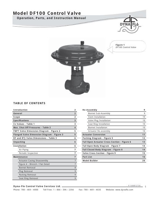
Model DF100 Control ValveOperation, Parts, and Instruction ManualFigure 1DF100 Control ValveTABLE OF CONTENTSIntroduction 2 Re-Assembly 9General 2 Bonnet Sub-Assembly 9Scope 2 Stem Installation 10Specifications 3 Valve Plug Installation 10Cv Values - Table 1 3 Seat Ring Installation 10Max. Shut Off Pressures - Table 2 4 Bonnet Installation 10FNPT Valve Dimension Diagram - Figure 2 5 Actuator Re-assembly 10Flanged Valve Dimension Diagram - Figure 3 5 Actuator Conversion 11RF and RTJ Valve Dimensions - Table 3 6 Packing Diagram - Figure 5 12Unpacking 6 Fail Open Actuator Cross-Section - Figure 6 13Installation 6 Fail Open Body Diagram - Figure 7 14Air Piping 7 Fail Closed Body Diagram - Figure 8 14Periodic Inspection 7 Valve Cross-Section - Figure 9 15Maintenance 7 Part List 16Actuator Casing Disassembly 7 Model Builder 20Figure 4 - Wrench / Flat Detail 7Bonnet Removal 8Plug Removal 9Packing Removal 9Seat Ring Removal 9Dyna-Flo Control Valve Services Ltd.Phone: 780 • 469 • 4000 Toll Free: 1 • 866 • 396 • 2356 Fax: 780 • 469 • 4035 Website: www.<strong>dyna</strong><strong>flo</strong>.comP-100M1213A1
Model DF100 Control ValveOperation, Parts, and Instruction ManualSPECIFICATIONSPort Diameters1/4”, 3/8”, 1/2”, 3/4”Valve Pressure Class / End Connection• 1” FNPT ASME B16.34 Class 900 (standard)• ASME 150 - 900 RF or RTJ (options)Maximum Pressure Drop2,250 Psig (155 Bar)Maximum Inlet Temperature and Pressures2,250 Psig (155 Bar) from -46 to 93 o C (-50 to 200 o F)2,185 Psig (155 Bar) at 149 o C (300 o F)Standard Shut-off ClassificationANSI Class IV ANSI / FCI 70-2DimensionsSee Figure 2Flow CharacteristicsQuick OpeningFlow DirectionUp or Down• Flow Down recommended for Quick Open application• Flow Up recommended for Throttling applicationsApproximate Weight20 lb (9 kg)Maximum Travel3/8 inch (10 mm)Material Temperature CapabilitiesBody Assembly-46 to 149 o C (-50 to 300 o F)Actuator Assembly-46 to 82 o C (-50 to 180 o F)Body StyleAvailable in Globe or Tee body styleBonnet/Body ConnectionThreadedActuator ConfigurationThe DF100 utilizes a on/off style spring and diaphragmactuator. Fail closed is field-reversible.Maximum Actuator Casing Pressure50 Psig (3.45 Bar)Effective Actuator Diaphragm Area33 inches 2 (213 cm 2 )Actuator Pressure Connections1/4 inch FNPTFor more information and other options contact your Dyna-Flosales office.DF100 C v ValuesTable 1Body Port Size Inch (mm) C v Value (100%)1/4 (6.4) 1.7Flow Up3/8 (9.5) 3.21/2 (12.7) 4.83/4 (19.1) 8.01/4 (6.4) 1.8Flow Down3/8 (9.5) 3.71/2 (12.7) 5.23/4 (19.1) 8.32Dyna-Flo Control Valve Services Ltd.Phone: 780 • 469 • 4000 Toll Free: 1 • 866 • 396 • 2356 Fax: 780 • 469 • 4035 Website: www.<strong>dyna</strong><strong>flo</strong>.comP-100M1213A3
Model DF100 Control ValveOperation, Parts, and Instruction ManualMaximum Allowable Shutoff Pressure DropsTable 2Number of SpringsNumber of SpringsActuator ActionFlow Direction(pressure tends to)Port DiameterInch0 - 20 Psig Operating Signal 0 - 35 Psig Operating Signal2 6 2 6Psi / Bar Psi / Bar Psi / Bar Psi / Bar1/4 1578 /109 2250 / 155 1578 / 109 2250 / 155Flow Up(open valve)3/8 657 / 45.3 1972 / 136 657 / 45.3 1972 / 1361/2 341 / 23.5 1025 / 70.7 341 / 23.5 1025 / 70.7Fail Closed3/4 60 / 4.14 180 / 12.4 60 / 4.14 180 / 12.41/4 523 / 36.1 1578 / 109 523 / 36.1 1578 / 109Flow Down(close valve)3/8 837 / 57.7 2250 / 155 837 / 57.7 2250 / 1551/2 * 2250 / 155 * 2250 / 1553/4 * 1603 / 111 * 2250 / 1551/4 2250 / 155 * 2250 / 155 2250 / 155Flow Up(open valve)3/8 2250 / 155 * 2250 / 155 2250 / 1551/2 1867 / 129 * 2250 / 155 2235 / 154Fail Open3/4 759 / 52.3 * 1882 / 130 834 / 57.71/4 2250 / 155 * 2250 / 155 2250 / 155Flow Down(close valve)3/8 2250 / 155 * 2250 / 155 2250 / 1551/2 2250 / 155 * 2250 / 155 2250 / 1553/4 1367 / 94.3 * 2250 / 155 1502 / 104* - Valve will not shut off.Dyna-Flo Control Valve Services Ltd.Phone: 780 • 469 • 4000 Toll Free: 1 • 866 • 396 • 2356 Fax: 780 • 469 • 4035 Website: www.<strong>dyna</strong><strong>flo</strong>.comP-100M1213A4
Model DF100 Control ValveOperation, Parts, and Instruction ManualØ9.90(Ø251)1/4 INCHNPT CONNECTION7.90(201)1/4 INCHNPT CONNECTION1.7(43)002.34(59)00Ø2.00(Ø51)2.34(59) 4.02(102)GLOBEBODY4.65(118)4.65(118)FRONT VIEW(GLOBE BODY)FRONT VIEW(TEE BODY)Ø2.00(Ø51)SIDE VIEW(TEE/GLOBE BODY)Ø9.90(Ø251)Figure 2 FNPT Style ValveDimensions (900 Cl. only)DFigure 3 Flanged Style ValveDimensions (table 3)00CBADyna-Flo Control Valve Services Ltd.Phone: 780 • 469 • 4000 Toll Free: 1 • 866 • 396 • 2356 Fax: 780 • 469 • 4035 Website: www.<strong>dyna</strong><strong>flo</strong>.comP-100M1213A5
Model DF100 Control ValveOperation, Parts, and Instruction ManualDF100 RF and RTJ Valve Dimensions (Refer to Figure 3)Inches (mm)Table 3Connection Class A BASME 150 6.75 (171) 3.38 (86)RFASME 300 7.25 (184) 3.63 (92)ASME 600 7.75 (197) 3.88 (99)ASME 900 8.63 (219) 4.32 (110)ASME 150 — —RTJASME 300 7.63 (194) 3.82 (97)ASME 600 7.75 (197) 3.88 (99)NOTE: FNPT <strong>valves</strong> dimensions are available in Figure 3.ASME 900 8.63 (219) 4.32 (110)UNPACKING VALVE FROM SHIPPING CONTAINERCheck the packing list against materials received, while unpacking the valve. The Packing List describes valve and accessories ineach shipping container.When lifting the valve from shipping container, it is advisable to grasp the valve by the bonnet and body to remove from package.Use caution, the approximate weight of the valve is 20 lbs. (9 kg); the actuator assembly may make lifting and carrying the valveawkward.INSTALLATIONFlowThe DF100 <strong>control</strong> valve is a bi-directional valve, although it is recommended that the DF100 be installed in <strong>flo</strong>w up position.The arrow on the front of the valve body (Key 1) indicates recommended <strong>flo</strong>w direction (<strong>flo</strong>w up) (See Figure 9 on Page 15).Before installing the valve, clean dirt, welding chips, scale or other foreign material from the line. Look for signs of gasketleakage through the line flanges. Make repairs, if required.WARNINGThe DF100 contol valve is sold standard in fail closed configuration. Do not tighten bonnet to body joint withoutfirst eliminating plug to seat contact! Tightening the bonnet / body joint with plug to seat contact will damage theseat and plug! Reference steps 1 of Bonnet Removal / Disassembly on Page 9.Dyna-Flo Control Valve Services Ltd.Phone: 780 • 469 • 4000 Toll Free: 1 • 866 • 396 • 2356 Fax: 780 • 469 • 4035 Website: www.<strong>dyna</strong><strong>flo</strong>.comP-100M1213A6
Model DF100 Control ValveOperation, Parts, and Instruction ManualINSTALLATION (Continued)1 When operating conditions allow, install the valve for thepreferred <strong>flo</strong>w direction. Refer to Table 2 for guide lines onshutoff pressure drops.NOTEThe normal method of installation is with theactuator in vertical position above the valve body.WARNINGKeep hands, hair and clothing away from all movingparts when operating the valve! Serious injury canresult from failure to do so!2 When possible, stroke the valve and check for smoothoperation through the full-stroke. Unsteady valve stemmovement could be an indication of an internal problem.Air PipingThe actuators are designed to accept 1/4” NPT connection. Use3/8” OD tubing (or equivalent) for all air lines. All connectionsmust be free of leaks.CAUTIONDo not exceed supply pressure indicated on serialplate located on the upper casing of the actuator.Periodic Inspection4 Clean the valve and repaint areas of severe oxidation.5 Ensure all accessories, mounting brackets and fastenersare secure.MAINTENANCEActuator Casing DisassemblyWARNINGWhen disassembling a Fail Closed DF100, it isnecessary to retain the valve stem and plug in theslightly open position. This is done by inserting a3/8” open end wrench as shown in Figure 4. Failureto retain the stem and plug will result in damage tothe seating surfaces!The following steps outline a Fail Closedactuator disassembly1 If the machined flats of the valve stem are not visiblethrough the bonnet window, it will be necessary to applysupply pressure to the valve in order to unseat the plugand expose the stem flats.2 Insert a 3/8” open end wrench onto the machined flats ofthe valve stem (See Figure 4). Remove the supply pressureso that the wrench rests flat on the face of the bonnet(Key 2), keeping the valve stem (key 5) flats fromretreating back into the bonnet and also keeping the plug(Key 4) from seating.CAUTIONUse safe work practices and lock out procedureswhen isolating <strong>valves</strong> and actuators! Always beaware of flammable instrument gas!1 Before performing any maintenance operation and to avoidinjury from sudden release of process pressure:AUse Safety lock-out procedures to be sure that theabove provisions stay in effect while you complete thework on your equipment.2 Check for process fluid leakage to the atmosphere throughthe body to bonnet joint and (if equipped) any NPTconnection.3 Examine the valve for damage caused by corrosive fumesor process drippings.Figure 4 Wrench / Stem Flat DetailDyna-Flo Control Valve Services Ltd.Phone: 780 • 469 • 4000 Toll Free: 1 • 866 • 396 • 2356 Fax: 780 • 469 • 4035 Website: www.<strong>dyna</strong><strong>flo</strong>.comP-100M1213A7
Model DF100 Control ValveOperation, Parts, and Instruction ManualMAINTENANCE (Continued)Actuator Casing Disassembly (Continued)3 Vent the pneumatic actuator loading pressure. Make surethe 3/8” wrench is securely in place and keeping the <strong>valves</strong>tem from moving.NOTEThe valve body can be serviced in-line (and withoutnecessarily disassembling the actuator, refer tostep 1 of Bonnet Removal / Disassembly on Page 9for <strong>instruction</strong>s). Release, or remove, all processpressure and fluid before servicing. If the valve is tobe serviced out of line, it is important that the body(Key 1) be firmly held in a clamping device. Seriousinjury can result from failure to do so!4 Begin by removing the 10 short (1”) cap screws (Key 26)from the actuator casings (Key 15 & 24) using two 9/16”wrenches or an impact wrench with a 9/16” socket.Be sure to leave the 2 long cap screws.CAUTIONThe springs inside the actuator casings are stillunder compression. It is necessary to take propersafety precautions and to follow proper procedures.5 Once the 10 short cap screws have been completelyremoved, begin loosening the two long (1-1/4”) cap screwsin an alternating pattern. During removal, try to keep theupper casing (Key 24) level until the springs are no longerunder compression, then completely remove the long capscrews and upper casing.NOTEFor a Fail Open actuator configuration, the actuatorsprings will not be immediately visible. The sequenceof steps for disassembly of a Fail Open actuator areas follows: steps 7, 11, 10, 9, 8 & 6.6 Remove the 6 actuator springs (Key 23) from thediaphragm plate (Key 20). To avoid plug and seat ringdamage, be sure to <strong>manual</strong>ly pull the diaphragm plate up(for fail closed configuration) so the plug is off the seatring. (See Maintenance WARNING on Page 7)7 A 5/8” wrench is required to remove the travel stop (Key22). Be sure to hold the 3/8” wrench (applied to the stemflats) with your other hand so that the stem does notrotate during travel stop removal.8 Remove the diaphragm plate spacer (Key 21) andinspect the spacer for damage.9 Remove the diaphragm plate (Key 20). Inspect thediaphragm plate for corrosion and damage.10 Remove the diaphragm and inspect surface for wear,stretching and tears. Replace if necessary.11 Remove the diaphragm plate washer (Key 18).See steps 1-10 of Actuator Conversion for <strong>instruction</strong>s onhow to re-assemble the actuator for a Fail Openconfiguration.12 To replace o-ring under lower casing use a 1-1/2” deepsocket or wrench to remove the bonnet lock nut (Key 17).13 Remove the flat washer (Key 16) and lower diaphragmcasing (Key 15). Take note of the position of the lowercasing for reassembly purposes.14 Remove the casing o-ring (Key 13) and inspect fordamage and disfigurement. Replace.Bonnet Removal / DisassemblyWARNINGBefore attempting to remove the bonnet takeextreme caution to assure that process pressureshave been removed and relieved. During the first fullcounter clockwise turn of the bonnet, the threadsshould begin to feel loose and the bonnet shouldrattle on the threads. If this does not occur, processpressure may still be present. Stop disassembly andinvestigate further. On Tee style bodies, a plug maybe removed to assure drainage.NOTETo remove the bonnet (Key 2) from the valve body(Key 1), it is not necessary to disassembly theactuator or even remove the body from the line.Service the body only after all process pressure andfluid are released or removed. If the valve is to beserviced out of line, it is important that the body befirmly held in a clamping device. Serious injury canresult from failure to do so!Dyna-Flo Control Valve Services Ltd.Phone: 780 • 469 • 4000 Toll Free: 1 • 866 • 396 • 2356 Fax: 780 • 469 • 4035 Website: www.<strong>dyna</strong><strong>flo</strong>.comP-100M1213A8
Model DF100 Control ValveOperation, Parts, and Instruction ManualMAINTENANCE (Continued)Bonnet Removal / Disassembly (Continued)1 With the 3/8” wrench still applied to the valve stem flats,use another wrench and remove the bonnet from the body.(See Maintenance WARNING on Page 7)Plug Removal2 Hold the 3/8” wrench (applied to the stem flats) in onehand, apply a 5/8” open end wrench to the flats of thevalve plug (Key 4) and remove the plug from the stem(Key 5). Inspect the plug and stem for thread damage,scratches or galling and replace plug if necessary.(See page 10 for Plug Installation steps)Packing Removal3 Place the bonnet in a clamping device and remove thebushing (Key 6) by sliding it off the valve stem (Key 5).Remove the bushing o-ring (Key 29) from the bushing andinspect the bushing for damage. Once the bushing (Key 6)is removed the disc springs (Key 8) may slide out, it maybe easier to remove them at this point before removing thevalve stem (Key 5) (Step 4).4 Remove the travel indicator (Key 12). Remove the <strong>valves</strong>tem (Key 5) by sliding it out towards the diaphragm endof the bonnet, away from the packing retainer end. Replaceany damaged parts.5 Remove the disc springs if not already removed (Key 8),packing follower (Key 9), packing rings (Key 11). Inspectentire packing box content for damage, corrosion,deformation and replace if necessary.Flip the Bonnet5 Using a standard mechanic’s “pick set” or a small flat headscrewdriver, remove the stem o-ring (Key 14), try not toscratch or damage the bonnet walls. Inspect and replaceo-ring if necessary.6 Remove and inspect the stem bushing (Key 7), replace ifnecessary. For <strong>instruction</strong>s on stem bushing insertion, seeBonnet Installation steps on page 11.Seat Ring Removal1 Remove the body o-ring (Key 29) and replace.2 Using a 1-1/16” socket remove the valve seat ring (Key 3)from the body. Inspect the seat for galling, scratches,corrosion and thread damage. Replace seat if necessary.3 Using a mechanic’s “pick set” or small flat head screwdriver, carefully remove the seat gasket (Key 28) from thebody. Be careful not to scratch the seat surface.4 Once the seat and gasket are removed from the body,thoroughly inspect the inside of the valve body forscratches, erosion, and damage. Replace body if necessary.NOTEIf there may be a delay before valve re-assembly, itmay be a good idea to cover the valve body.REASSEMBLYBonnet Sub-assembly (Reference Figure 5)1 With the bonnet (Key 2) sitting actuator side up, install thestem bushing (Key 7) through the bonnet window and upinto the stem bore. Make sure that the “keeper lips” (ridge)of the bushing is inserted up into the bonnet. It may benecessary to depress the “tabs” of the bushing in order toinsert it. Push the bushing into the bonnet until thebushing “snaps” into place.2 Lubricate the stem o-ring (Key 14) with o-ring lubricant andinstall the o-ring into the o-ring groove in the top of thebonnet. Use a flat head screwdriver to help work the o-ringcarefully into the groove so as not to cut the o-ring ordamage the bonnet.Flip the bonnet3 Lubricate the packing rings (Key 11) and install the packingrings into the packing bore as per Figure 5. Make sure therings touch the spacer.4 Install the packing follower (Key 9) over the packing ringswith the flat face towards the packing rings.5 Install the 4 disc springs(Key 8), see Figure 5 for the orderof installation.6 Lubricate the bushing o-ring (Key 29) and slide it onto thebushing (Key 6) as shown in Figure 5. Insert the bushingwith the bushing o-ring facing the Belleville washers (Key 8)into the bonnet (Key 2) so that the bushing (Key 6) has anapproximate 0.80” gap between it and the bonnet (Key 2).See Figure 5 for detail.7 Install the bushing washer (Key 32) on to the bushing seatinside of the valve body. See Figure 5 and 9 for detail.Flip the bonnetDyna-Flo Control Valve Services Ltd.Phone: 780 • 469 • 4000 Toll Free: 1 • 866 • 396 • 2356 Fax: 780 • 469 • 4035 Website: www.<strong>dyna</strong><strong>flo</strong>.comP-100M1213A9
Model DF100 Control ValveOperation, Parts, and Instruction ManualREASSEMBLY (Continued)Stem Installation (Continued)8 It is important to insert the valve stem (Key 5) into thebonnet starting from the actuator end (opposite from thepacking retainer) with the plug threads first. Be carefulwhen inserting the stem so that the stem flats do notdamage the stem o-ring. The plug end on the <strong>valves</strong>tem should protrude slightly past the bushing so that thestem flats are still visible in the bonnet window. Align thestem flats to run parallel to the bonnet window.Valve Plug Installation9 Apply medium strength liquid thread locker to the threadsof the valve plug (Key 4).10 Apply a 3/8” open end wrench to the machined stemflats. Thread the plug (Key 4) and using a 5/8” wrench(applied to the flats of the plug) fully tighten the pluginto the stem (approximately 24 ft-lb). NOTE: To avoiddamage, it may be necessary to <strong>manual</strong>ly pull up on thevalve stem until the valve plug makes contact with thebushing (Key 6) during bonnet installation. Packing boxparts are loose inside until bonnet is tightened.Seat Ring InstallationWith the body secured in a clamping device (do not overtighten device on valve body)1 Clean and inspect the inside of the valve body (Key 1),make sure there is no debris or damage. Coat both sides ofthe seat ring gasket (Key 28) with nickel based anti-seizecompound. Place the seat ring gasket inside the body, usea small flat head screwdriver to help carefully align thegasket to be concentric with the bore.2 Apply the nickel based anti-seize compound to the threadsof the seat ring (Key 3). Carefully place the seat ring insidethe body (hex head up) and thread the seat ring into thebody. Torque seat ring to 150 ft-lb.NOTEAny significant resistance to seat ring installationshould be investigated. Dry threads could preventproper seating of the seat ring against the gasket,allowing leakage.3 Lubricate the body o-ring (Key 30) with o-ring lubricant.Install the o-ring on the top gasket face of the body.4 Lubricate the internal threads of the body with nickel basedanti-seize compound.Bonnet InstallationNOTEIt is important to make sure that the valve plug willnot make contact with the seat ring during bonnetinstallation. Apply a 3/8” wrench to the stem flats ifnecessary. (See NOTE in Step 10 of Valve PlugInstallation on Page 10)5 Thread the bonnet sub-assembly into the body until handtight. Use a wrench to tighten the bonnet into the bodyapproximately 300 ft-lb. (Make sure the bushing washer(Key 32) is properly seated on the bushing seat inside thevalve body. See Step 7, page 10.)6 Lubricate the casing o-ring (Key 13) with o-ring lubricantand insert it into the top o-ring groove of the bonnet.Actuator Reassembly (Fail Closed)WARNINGWhen disassembling a Fail Closed DF100, it isnecessary to retain the valve stem and plug in theslightly open position. This is done by inserting a3/8” open end wrench as shown in Figure 4. Failureto retain the stem and plug will result in damage tothe seating surfaces!1 If maintenance has occurred and the valve has beendisassembled, after the bonnet has been installed into thevalve body leave the body in the clamping device.2 Place the lower diaphragm casing (Key 15) over the <strong>valves</strong>tem so that it rests on the casing o-ring (Key 13).Orientate the NPT connection of the casing so that it iscentered within the bonnet window (Key 2). ReferenceFigures 2 and 9 for correct NPT orientation.3 Install the flat washer (Key 16) over the valve stem so thatit rests on the lower casing.4 Apply nickel based anti-seize compound to the exposedbonnet threads.5 While holding the lower casing in place, thread the bonnetlocknut (Key 17) onto the bonnet using a 1-1/2” deepsocket tighten to 200 ft-lb.Dyna-Flo Control Valve Services Ltd.Phone: 780 • 469 • 4000 Toll Free: 1 • 866 • 396 • 2356 Fax: 780 • 469 • 4035 Website: www.<strong>dyna</strong><strong>flo</strong>.comP-100M1213A10
Model DF100 Control ValveOperation, Parts, and Instruction Manual6 Install the diaphragm plate washer (Key 18) over the <strong>valves</strong>tem (Key 5).7 Place the diaphragm (Key 19) over the stem so that it is incontact with the diaphragm plate washer. Be sure to alignthe holes of the diaphragm with the bolt holes on the lowercasing (Key 15).8 Slide the diaphragm plate (Key 20) over the stem so that itrests with the flat face against the diaphragm. ReferenceFigure 8 for correct diaphragm plate placement.9 Install the diaphragm plate spacer (Key 21) over the stemso that it rests on top of the diaphragm plate.10 Apply medium strength liquid thread locker to the threadsof the travel stop (Key 22) and thread it onto the <strong>valves</strong>tem. Be sure to hold the 3/8” wrench applied to thestem flats to keep the stem from rotating whiletightening the travel stop. Using a 5/8” socket, torquedown the travel stop to 20 ft-lb.11 Place the springs (Key 23) on the diaphragm plate in acircular pattern, with each spring centered on the plateprotrusions.NOTEA conversion from fail open to fail closed (or viseversa) may not be possible without 4 extra springs(dependant on shutoff pressure needed see Table 2).12 Place the upper casing (Key 24) over the springs, be surethat the NPT connection of the upper casing is aligned withthe NPT connection of the lower casing. Also, be sure thatthe bolt holes of the upper casing are aligned with the boltholes of the lower casing.13 Install both of the long (1-1/4”) cap screws (Key 25)opposite from each other and in line with the valve body.Partially thread a nut (Key 27) onto one of the long capscrews.14 It may be necessary to compress the springs by pushingslightly on the upper casing to thread a nut onto thesecond long cap screw. Using two 9/16” wrenches orsocket set, tighten the two long cap screws using analternating pattern. Until the 10 short cap screws can beinstalled and the nuts threaded on. Try to keep the upperdiaphragm casing level during this process.15 Completely tighten the 12 nuts.16 Install the vent cap (Key 31) to the NPT connection on theupper casing.17 It will be necessary to apply supply pressure to theactuator in order to remove the 3/8” wrench on the stemflats.ACTUATOR CONVERSIONFail Open AssemblyNOTEIf actuator conversion is all that is required ando-ring and bonnet maintenance is unnecessary,complete disassembly of the lower casing will not berequired. Follow steps 1-11 of actuator disassemblyon page 6. Actuator assembly and maintenanceshould only be performed by trained individualsadhering to proper procedures and safetyprecautions.Reference Figure 6 on Page 13 for diagram.NOTEA conversion from fail open to fail closed (or viseversa) may not be possible without 4 extra springs(dependant on shutoff pressure needed see Table 2).1 If the actuator has not yet been disassembled, refer toActuator Casing Disassembly on Page 7. It may beunnecessary to disassemble the actuator passed step 11.2 Install the diaphragm plate spacer (Key 22) over the stem.3 Set the required springs (Key 24) onto the inside of thelower casing, spacing them equally in a circular pattern.Position the springs so that they will line up with the raisedbumps of the diaphragm plate (Key 21).4 Place the diaphragm plate over the valve stem so that theconcave face touches the springs and the protrusionlocates inside the spring.5 Place the diaphragm (Key 20) over the stem so that it is incontact with the diaphragm plate. Make sure the holes onthe diaphragm are aligned with the bolt holes on thecasing.6 Install the diaphragm plate washer (Key 19) over the <strong>valves</strong>tem so that it rests on top of the diaphragm.Dyna-Flo Control Valve Services Ltd.Phone: 780 • 469 • 4000 Toll Free: 1 • 866 • 396 • 2356 Fax: 780 • 469 • 4035 Website: www.<strong>dyna</strong><strong>flo</strong>.comP-100M1213A11
Model DF100 Control ValveOperation, Parts, and Instruction ManualACTUATOR CONVERSION (Continued)Fail Open Assembly (Continued)7 Apply medium strength liquid thread locker to the threadsof the travel stop (Key 23) and thread it onto the stem.8 Apply a 3/8” wrench to the machined flats of the <strong>valves</strong>tem (Key 5) to prevent stem movement during travelstop installation. Using a 5/8” socket, torque down thetravel stop to 20 ft-lb.9 Install the two long (1-1/4”) cap screws (Key 26)opposite each other making sure they are in line with thewith the valve body (this is to prevent futurecomplications). Install the 10 short (1”) cap screws (Key27) and thread a nut (Key 28) onto all 12 cap screws.Using two 9/16” wrenches or socket set, completelytighten all the nuts and cap screws.10 Install the vent cap (Key 31) to the NPT connection on thelower casing. Remove the 3/8” wrench from the stemflats.STEM O-RING (KEY 14)STEM BUSHING (KEY 7)TRAVEL INDICATOR (KEY 12)BONNET (KEY 2)STEM (KEY 5)PACKING RINGS (KEY 11)PACKING FOLLOWER (KEY 9)DISC SPRINGS (KEY 8)(4 SHOWN)BUSHING O-RING (KEY 29)BODY O-RING (KEY 30) BUSHING WASHER (KEY 32)VALVE PLUG (KEY 4)BUSHING (KEY 6)Figure 5 Packing Installation DiagramDyna-Flo Control Valve Services Ltd.Phone: 780 • 469 • 4000 Toll Free: 1 • 866 • 396 • 2356 Fax: 780 • 469 • 4035 Website: www.<strong>dyna</strong><strong>flo</strong>.comP-100M1213A12
Model DF100 Control ValveOperation, Parts, and Instruction Manual19 24 2322 18202625211431lower casing shownrotated 90 o for clarity2751316151727NOTE: Refer toTable 2 for the requirednumber of springs (Key 24) for actuatorshut off.Figure 6 Fail Open Cross SectionDyna-Flo Control Valve Services Ltd.Phone: 780 • 469 • 4000 Toll Free: 1 • 866 • 396 • 2356 Fax: 780 • 469 • 4035 Website: www.<strong>dyna</strong><strong>flo</strong>.comP-100M1213A13
Model DF100 Control ValveOperation, Parts, and Instruction ManualFigure 7Fail Open Globe BodyCross SectionFigure 8Fail Closed Tee BodyCross SectionDyna-Flo Control Valve Services Ltd.Phone: 780 • 469 • 4000 Toll Free: 1 • 866 • 396 • 2356 Fax: 780 • 469 • 4035 Website: www.<strong>dyna</strong><strong>flo</strong>.comP-100M1213A14
Model DF100 Control ValveOperation, Parts, and Instruction Manual19 24 233122 2120262518271413721611515171289293064321328Figure 9 Fail Closed Cross Section FNPTDyna-Flo Control Valve Services Ltd.Phone: 780 • 469 • 4000 Toll Free: 1 • 866 • 396 • 2356 Fax: 780 • 469 • 4035 Website: www.<strong>dyna</strong><strong>flo</strong>.comP-100M1213A15
Model DF100 Control ValveOperation, Parts, and Instruction ManualPARTS LISTKey Description Material Part Number1 Body LCCGlobeDF10301X01DTeeDF10307X01D2 Bonnet LCC DF10201X21D3 Seat Ring1/4 Inch Port S17400 DH1150 DF10514X01D3/8 Inch Port S17400 DH1150 DF10538X01D1/2 Inch Port S17400 DH1150 DF10512X01D3/4 Inch Port S17400 DH1150 DF10502X01D1/4 Inch Port S17400 DH1150 Nitrided DF10514X01D-N3/8 Inch Port S17400 DH1150 Nitrided DF10538X01D-N1/2 Inch Port S17400 DH1150 Nitrided DF10512X01D-N3/4 Inch Port S17400 DH1150 Nitrided DF10534X01D-N1/4 Inch Port S17400 DH1150 - Alloy 6 DF10514X04D3/8 Inch Port S17400 DH1150 - Alloy 6 DF10538X04D1/2 Inch Port S17400 DH1150 - Alloy 6 DF10512X04D3/4 Inch Port S17400 DH1150 - Alloy 6 DF10534X04D1/4 Inch Port S17400 DH1150 Tungsten Carbide DF10514X07D3/8 Inch Port S17400 DH1150 Tungsten Carbide DF10538X07D1/2 Inch Port S17400 DH1150 Tungsten Carbide DF10512X07D3/4 Inch Port S17400 DH1150 Tungsten Carbide DF10534X07D4 Valve Plug1/4 — 1/2 Inch (1/4 & 3/8 Inch Port) S17400 DH1150 DF10501X01D3/4 Inch S17400 DH1150 DF10502X01D1/4 — 1/2 Inch (1/4 & 3/8 Inch Port) S17400 DH1150 Nitrided DF10501X01D-N3/4 Inch S17400 DH1150 Nitrided DF10502X01D-N1/4 Inch S17400 DH1150 - Alloy 6 DF10614X04D3/8 Inch S17400 DH1150 - Alloy 6 DF10638X04D1/2 Inch S17400 DH1150 - Alloy 6 DF10612X04D3/4 Inch S17400 DH1150 - Alloy 6 DF10634X04D1/4 — 1/2 Inch (1/4 & 3/8 Inch Port) S17400 DH1150 Tungsten Carbide DF10501X07D3/4 Inch S17400 DH1150 Tungsten Carbide DF10502X07D5 Valve Stem S31600/S31603 Dual Grade DF10302X01D6 Bushing S17400 DH1150 DF10216X01D7 Stem Bushing Ryton (PPS) DF10205X01D8 Disc Springs (4 Required) N07718 Part of Spring Pack9 Packing Follower S31600 Part of Spring Pack11 Packing Rings PTFE / Carbon PTFE DF10206X01D12 Travel Indicator Zinc Plated Steel DF10310X01D13 Casing O-Ring Hydrogenated Nitrile (HNBR) DF10209X01D14 Stem O-Ring Hydrogenated Nitrile (HNBR) DF10210X01DDyna-Flo Control Valve Services Ltd.Phone: 780 • 469 • 4000 Toll Free: 1 • 866 • 396 • 2356 Fax: 780 • 469 • 4035 Website: www.<strong>dyna</strong><strong>flo</strong>.comP-100M1213A16
Model DF100 Control ValveOperation, Parts, and Instruction ManualOur Commitment to QualityDyna-Flo is committed to continuous improvement. While all efforts have been made to ensure the accuracy of the content inthis document, modifications or improvements to the information, specifications, and designs may occur at any time withoutnotice. This document was published for informational purposes only, and does not express or imply suitability, a warranty,or guarantee regarding the products or services described herein or their use or applicability.Neither Dyna-Flo Control Valve Services Ltd., nor any of their affiliated entities assumes responsibility for the selection, useand maintenance of any product. Responsibility for selection, use and maintenance of any product remains with the purchaserand end-user.Dyna-Flo Control Valve Services Ltd.Phone: 780 • 469 • 4000 Toll Free: 1 • 866 • 396 • 2356 Fax: 780 • 469 • 4035 Website: www.<strong>dyna</strong><strong>flo</strong>.comP-100M1213A19
Model DF100 Control ValveOperation, Parts, and Instruction ManualOrdering GuideDyna-Flo DF100 Control Valve | Model Numbering SystemSample Part NumberDF100-GC3-6BF-14S-XXSCodeXDescriptionSpecialTrim MaterialS S17400 DH 1150T Tungsten CarbideN S17400 NitridedA S17400 / Alloy 614FB6Trim Size14 1/4” 38 3/8”12 1/2” 34 3/4”Connection StyleF RF J RTJN NPTASME RatingA 150 B 300C 600 D 900 (Standard for FNPT)Number of Springs2 2 Springs6 6 Springs3Spring Range3 Size 25 Actuator with 3-15 Spring6 Size 25 Actuator with 6-30 SpringCCOActuator StyleFail ClosedFail OpenGBody StyleG Globe Style T Tee StyleDyna-Flo Control Valve Services Ltd.Phone: 780 • 469 • 4000 Toll Free: 1 • 866 • 396 • 2356 Fax: 780 • 469 • 4035 Website: www.<strong>dyna</strong><strong>flo</strong>.comP-100M1213A20