Haas lifting instruction_lathe and mill
Haas lifting instruction_lathe and mill
Haas lifting instruction_lathe and mill

Create successful ePaper yourself
Turn your PDF publications into a flip-book with our unique Google optimized e-Paper software.
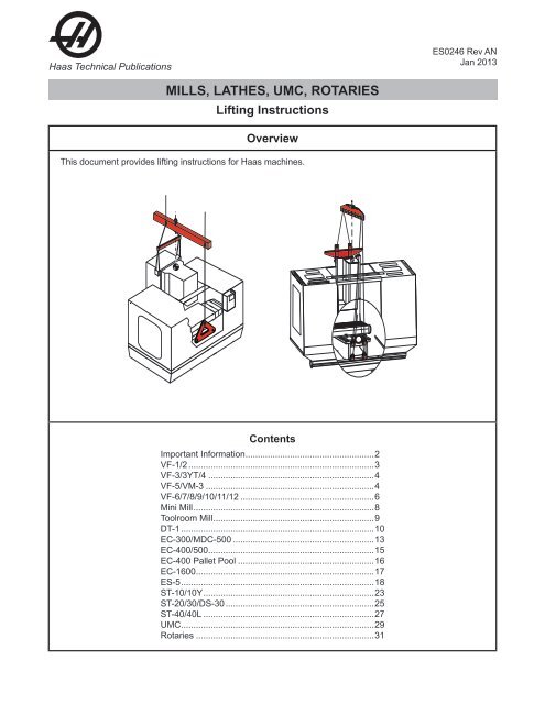
<strong>Haas</strong> Technical Publications<br />
ES0246 Rev AN<br />
Jan 2013<br />
MILLS, <strong>lathe</strong>s, UMC, rotaries<br />
Lifting Instructions<br />
Overview<br />
This document provides <strong>lifting</strong> <strong>instruction</strong>s for <strong>Haas</strong> machines.<br />
Contents<br />
Important Information.....................................................2<br />
VF-1/2............................................................................3<br />
VF-3/3YT/4....................................................................4<br />
VF-5/VM-3.....................................................................4<br />
VF-6/7/8/9/10/11/12.......................................................6<br />
Mini Mill..........................................................................8<br />
Toolroom Mill..................................................................9<br />
DT-1...............................................................................10<br />
EC-300/MDC-500..........................................................13<br />
EC-400/500....................................................................15<br />
EC-400 Pallet Pool........................................................16<br />
EC-1600.........................................................................17<br />
ES-5...............................................................................18<br />
ST-10/10Y......................................................................23<br />
ST-20/30/DS-30.............................................................25<br />
ST-40/40L......................................................................27<br />
UMC...............................................................................29<br />
Rotaries.........................................................................31
<strong>Haas</strong> Technical Publications<br />
Lifting Instructions<br />
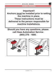
Important Information<br />
Please read these <strong>instruction</strong>s in their entirety before attempting to lift the <strong>mill</strong>.<br />
WARNING<br />
It is imperative that preparation <strong>and</strong> <strong>lifting</strong> of the machine be<br />
performed by PROFESSIONAL RIGGERS. These <strong>instruction</strong>s are to be<br />
used as a reference guide only.<br />
Specialized equipment is necessary to ensure that the machine is secure <strong>and</strong> level while being raised.<br />
IMPORTANT: VF-Series - The top column attachment points are the main <strong>lifting</strong> points <strong>and</strong> should remain<br />
vertically oriented to the floor throughout the entire lift.<br />
The front chains attached to the base are to help stabilize the machine <strong>and</strong> should not carry the main<br />
load.<br />
When <strong>lifting</strong> the machine, slowly lift until all chains are taut, then lift the machine ensuring it remains<br />
balanced.<br />
Lifting brackets <strong>and</strong> hardware must be removed before machine operation, unless otherwise noted.<br />
Lifting kits are available for most machines. Kits include <strong>lifting</strong> brackets <strong>and</strong> mounting hardware. It is<br />
the customer's responsibility to supply all chains <strong>and</strong> spreader bars required to properly lift the machine.<br />
Contact a local <strong>Haas</strong> Factory Outlet (HFO) for more information.<br />
Store <strong>lifting</strong> brackets <strong>and</strong> hardware in a safe place. They must be used if the machine is to be moved. Only<br />
<strong>Haas</strong> supplied replacement hardware is authorized for use. If <strong>lifting</strong> hardware is lost or damaged, contact<br />
your HFO.<br />
Refer to the <strong>lifting</strong> placard located on the rear of the machine for model specific <strong>lifting</strong> information.<br />
For <strong>lifting</strong> of machines built before Oct 2012, refer to ES0246 Rev AL available from <strong>Haas</strong> Automation.<br />
ES0246 Rev AN Jan 2013 Page 2 of 31
<strong>Haas</strong> Technical Publications<br />
Lifting Instructions<br />
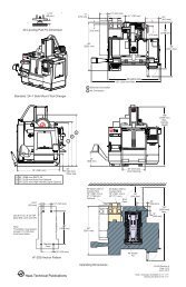
Vertical Machining Centers<br />
VF-1 Series, VF-2 Series, VM-2 Lift Placard<br />
Refer to the <strong>lifting</strong> placard for small VMCs. Attach the <strong>lifting</strong> bracket <strong>and</strong> chains as shown. Ensure that the<br />
chains do not contact the sheet metal enclosure or electrical cables. Note the use of spreader bars.<br />
90°<br />
13"<br />
(330 mm)<br />
14"<br />
(356 mm)<br />
VF-1<br />
VF-2<br />
45"<br />
(1143 mm)<br />
VF-2YT<br />
VM-2<br />
51"<br />
(1295 mm)<br />
90°<br />
24"<br />
(607 mm)<br />
6' 10" (2083 mm)<br />
19" (483 mm)<br />
29-0881A Rev A<br />
© 2012 <strong>Haas</strong> Automation, Inc.<br />
ES0246 Rev AN Jan 2013 Page 3 of 31
<strong>Haas</strong> Technical Publications<br />
Lifting Instructions<br />
Medium VMC Lift Placard<br />
Refer to the <strong>lifting</strong> placard for medium VMCs. Attach chains to the <strong>lifting</strong> points as shown. Ensure that the<br />
chains do not contact the sheet metal enclosure or electrical cables. Note the use of spreader bars.<br />
13" (330 mm)<br />
16" (406 mm)<br />
Medium VMC<br />
51" (1295 mm)<br />
29" (737 mm)<br />
VF-3<br />
VF-4<br />
9' 6"<br />
(2896 mm)<br />
29" (737 mm)<br />
90°<br />
90°<br />
18" (457 mm)<br />
65" (1651 mm)<br />
16" (406 mm)<br />
9' 6"<br />
(2896 mm)<br />
29" (737 mm)<br />
VF-3YT<br />
VF-5<br />
VM-3<br />
29-0882A Rev A<br />
© 2012 <strong>Haas</strong> Automation, Inc.<br />
ES0246 Rev AN Jan 2013 Page 4 of 31
<strong>Haas</strong> Technical Publications<br />
Lifting Instructions<br />
VF-3/4 Lifting Hardware Details<br />
1. Install two <strong>lifting</strong> brackets with 1/2"-13 SHCS<br />
<strong>and</strong> 1/2" hard washers. Use one washer above<br />
the bracket <strong>and</strong> two below. H<strong>and</strong> tighten only.<br />
VF-3YT/5, VM-3 Lifting Hardware Details<br />
1. Install two 5/8"-11 eyebolts into the base<br />
casting near the Y-axis way cover. H<strong>and</strong><br />
tighten the eyebolt with the eye facing the front<br />
of the machine.<br />
ES0246 Rev AN Jan 2013 Page 5 of 31
<strong>Haas</strong> Technical Publications<br />
Lifting Instructions<br />
Large VMC Lift Placard<br />
Refer to the <strong>lifting</strong> placard for large VMCs. Attach chains to the <strong>lifting</strong> points as shown. Ensure that the<br />
chains do not contact the sheet metal enclosure or electrical cables. Note the use of spreader bars <strong>and</strong><br />
spacers.<br />
VF-6/7/10/12: 83" (2108 mm)<br />
VF-8/9/11: 106" (2692 mm)<br />
VF-6/7/10/12, VM-6: 39" (991 mm)<br />
VF-8/9/11, VR-8/11: 46" (1168 mm)<br />
106"<br />
(2692 mm)<br />
117"<br />
(2972 mm)<br />
VF-8/9/11: 46" (1168 mm)<br />
VF-6/7/10/12: 47" (1194 mm)<br />
40"<br />
(1020 mm)<br />
90°<br />
90°<br />
29-0883A Rev A<br />
© 2012 <strong>Haas</strong> Automation, Inc.<br />
ES0246 Rev AN Jan 2013 Page 6 of 31
<strong>Haas</strong> Technical Publications<br />
Lifting Instructions<br />
VF-6 to 12, VM-6, VR-8/11 Lifting Hardware Details<br />
1. The <strong>lifting</strong> bracket can be found beneath<br />
the step enclosure. Remove the two steps<br />
located on the sides of the Y-axis way cover.<br />
1. Remove<br />
screws<br />
2. Slide step<br />
out<br />
2. The bracket will remain in place after <strong>lifting</strong><br />
operation is complete. Replace the steps<br />
over the <strong>lifting</strong> brackets.<br />
Remove the step from the inside-front enclosure<br />
The <strong>lifting</strong> brac<br />
Lifting<br />
Bracket<br />
ES0246 Rev AN Jan 2013 Page 7 of 31
<strong>Haas</strong> Technical Publications<br />
Lifting Instructions<br />
Mini Mill Lift Placard<br />
<strong>Haas</strong> Automation does not provide a <strong>lifting</strong> kit for the Mini Mill. It is the machine rigger’s responsibility to<br />
provide the means to lift <strong>and</strong> position the Mini Mill. The customer must supply all hardware required for<br />
<strong>lifting</strong>.<br />
Attach chains to the <strong>lifting</strong> points as shown. Ensure that the chains do not contact the sheet metal enclosure<br />
or electrical cables. Note the use of spreader bars.<br />
ES0246 Rev AN Jan 2013 Page 8 of 31
<strong>Haas</strong> Technical Publications<br />
Lifting Instructions<br />
TM-1/1P to TM-3/3P Lift Placard<br />
<strong>Haas</strong> Automation does not provide a <strong>lifting</strong> kit for the Toolroom Mill. It is the machine rigger’s responsibility<br />
to provide the means to lift <strong>and</strong> position the Toolroom Mill. The customer must supply all hardware required<br />
for <strong>lifting</strong>. Attach chains to the <strong>lifting</strong> points as shown. Ensure that the chains do not contact the sheet metal<br />
enclosure or electrical cables.<br />
TM-1/1P <strong>and</strong> TM-2/2P: The front <strong>lifting</strong> points are 1/2"-13 tapped holes.<br />
TM-3/3P: Remove the pendant arm shipping bracket before installing hardware. Move the pendant arm to<br />
the operating position <strong>and</strong> secure in place to avoid damage from <strong>lifting</strong> chains. The front <strong>lifting</strong> points are<br />
1/2" (13 mm) through holes which will accept 1/2" (13 mm) eyebolts, washers, <strong>and</strong> nuts.<br />
*<br />
45" (1140 mm) TM-1/1P/2/2P<br />
57" (1450 mm) TM-3/3P<br />
TM-1/1P<br />
TM-2/2P<br />
TM-3/3P<br />
4500 lb<br />
(2050 kg)<br />
5000 lb<br />
(2300 kg)<br />
6500 lb<br />
(2950 kg)<br />
41"<br />
(1041 mm)<br />
TM-3/3P<br />
97"<br />
(2460 mm)<br />
TM-1/1P<br />
TM-2/2P<br />
110"<br />
(2790 mm)<br />
TM-1/1P: 18" (432 mm)<br />
TM-2/2P: 20" (483 mm)<br />
TM-3/3P: 30" (762 mm)<br />
TM-3/3P<br />
ø1/2" (13mm) Through Hole<br />
TM-1/1P/2/2P<br />
ø1/2"-13 Threaded Hole<br />
29-0888A Rev A<br />
© 2012 <strong>Haas</strong> Automation, Inc.<br />
ES0246 Rev AN Jan 2013 Page 9 of 31
<strong>Haas</strong> Technical Publications<br />
Lifting Instructions<br />
DT-1 Lift Placard<br />
Refer to the <strong>lifting</strong> placard for the DT-1. Attach <strong>lifting</strong> chains <strong>and</strong> hooks to the <strong>lifting</strong> points as shown. Ensure<br />
that the chains do not contact the sheet metal enclosure or electrical cables.<br />
2 x 156"<br />
(3962 mm)<br />
2 x 100"<br />
(2540 mm)<br />
34"<br />
(864 mm)<br />
12"<br />
(305 mm)<br />
ES0246 Rev AN Jan 2013 Page 10 of 31
<strong>Haas</strong> Technical Publications<br />
Lifting Instructions<br />
DT-1 Lifting Hardware Details<br />
1. Loosen, but do not remove the top row of<br />
screws for the Y-axis way cover.<br />
Loosen<br />
2. Remove the two lower screws.<br />
Remove<br />
3. Remove the two bolts on the front sides of the<br />
Y-axis way cover.<br />
Remove<br />
ES0246 Rev AN Jan 2013 Page 11 of 31
<strong>Haas</strong> Technical Publications<br />
Lifting Instructions<br />
4. Lift up the Y-axis way cover over the linear<br />
guides <strong>and</strong> push the cover toward the table.<br />
5. Install the eyebolts <strong>and</strong> necessary shackles.<br />
6. Remove the screws to open the roof access<br />
panel for <strong>lifting</strong> strap access.<br />
ES0246 Rev AN Jan 2013 Page 12 of 31
<strong>Haas</strong> Technical Publications<br />
Lifting Instructions<br />
Horizontal Machining Centers<br />
EC-300/MDC-500 Lift Placard<br />
Refer to the <strong>lifting</strong> placard for EC-300/MDC-500. Attach chains to the <strong>lifting</strong> points as shown. Ensure that<br />
the chains do not contact the sheet metal enclosure or electrical cables.<br />
ES0246 Rev AN Jan 2013 Page 13 of 31
<strong>Haas</strong> Technical Publications<br />
Lifting Instructions<br />
EC-300/MDC-500 Lifting Hardware Details<br />
1. Before <strong>lifting</strong> the machine, remove the hole<br />
plugs <strong>and</strong> install four 1"-8 TPI forged steel<br />
shoulder eyebolts, 1" steel washers <strong>and</strong><br />
spacers.<br />
EC-300 Only<br />
Top Panels<br />
EC-300 only - Remove the two top panels.<br />
C<br />
42” (107 cm)<br />
16” (41 cm)<br />
2. Once the machine is in position, remove the<br />
eyebolts from the <strong>lifting</strong> holes <strong>and</strong> replace with<br />
bolts <strong>and</strong> washers<br />
3. After installation, re-install the chip screen with<br />
bolts <strong>and</strong> washers.<br />
This dimension is<br />
critical to prevent the<br />
lift chain from<br />
contacting the<br />
spindle head cover.<br />
*<br />
*<br />
25”<br />
(64 cm)<br />
MDC<br />
Chip Screen<br />
DUAL PA LET<br />
INLINE<br />
SPINDLE<br />
*<br />
*<br />
4X Lifting Eyebolt<br />
Spacer<br />
4X Forged Steel Shoulder Eyebolt<br />
1”- 8 TPI <strong>and</strong> 1” Steel Washer<br />
Min 9000 lb Working Load<br />
Limit (WLL) at Vertical Pull (08)<br />
ES0246 Rev AN Jan 2013 Page 14 of 31
<strong>Haas</strong> Technical Publications<br />
Lifting Instructions<br />
EC-400/500 Lift Placard<br />
Refer to the <strong>lifting</strong> placard for EC-400/500. Attach chains to the <strong>lifting</strong> points as shown. Ensure that the<br />
chains do not contact the sheet metal enclosure or electrical cables.<br />
ES0246 Rev AN Jan 2013 Page 15 of 31
<strong>Haas</strong> Technical Publications<br />
Lifting Instructions<br />
EC-400/500 Lifting Hardware Details<br />
1. Remove the top front panels of the machine.<br />
2. Before <strong>lifting</strong> the machine, remove the hole<br />
plugs <strong>and</strong> install four 1"-8 TPI forged steel<br />
shoulder eyebolts, 1" steel washers, <strong>and</strong><br />
spacers.<br />
Top Front Panels<br />
3. Once the machine is in position, remove the<br />
eyebolts from the <strong>lifting</strong> holes <strong>and</strong> replace with<br />
bolts <strong>and</strong> washers.<br />
EC<br />
400<br />
EC<br />
400<br />
ES0246 Rev AN Jan 2013 Page 16 of 31
<strong>Haas</strong> Technical Publications<br />
Lifting Instructions<br />
EC-400 Pallet Pool Lift Placard<br />
Refer to the <strong>lifting</strong> placard for the EC-400 pallet pool. Attach chains to the <strong>lifting</strong> points as shown. Ensure<br />
that the chains do not contact the sheet metal enclosure or electrical cables.<br />
ES0246 Rev AN Jan 2013 Page 17 of 31
<strong>Haas</strong> Technical Publications<br />
Lifting Instructions<br />
EC-400 Pallet Pool Lifting Hardware Details<br />
1. Before <strong>lifting</strong> the machine, install four (4) 5/8"<br />
x 1-1/16" eyebolts <strong>and</strong> four 5/8" flat washers.<br />
Note: The two left eyebolts are installed into<br />
blocks bolted to the base plate.<br />
2. Once the machine is in position, remove the<br />
eyebolts from the <strong>lifting</strong> holes <strong>and</strong> replace with<br />
bolts <strong>and</strong> washers.<br />
ES0246 Rev AN Jan 2013 Page 18 of 31
<strong>Haas</strong> Technical Publications<br />
Lifting Instructions<br />
EC-1600 Lift Placard<br />
Refer to the <strong>lifting</strong> placard for EC-1600. Attach chains to the <strong>lifting</strong> points as shown. Ensure that the chains<br />
do not contact the sheet metal enclosure or electrical cables.<br />
ES0246 Rev AN Jan 2013 Page 19 of 31
<strong>Haas</strong> Technical Publications<br />
Lifting Instructions<br />
EC-1600 Lifting Hardware Details<br />
1. Wheels can be used to help position the <strong>lifting</strong><br />
beams beneath the EC-1600. The <strong>lifting</strong> kit<br />
(LK1600) is available from <strong>Haas</strong> Automation.<br />
2. Position the <strong>lifting</strong> beams under the machine so<br />
that the EC-1600 is located in the <strong>lifting</strong> beam<br />
recesses.<br />
EC-1600<br />
ES0246 Rev AN Jan 2013 Page 20 of 31
<strong>Haas</strong> Technical Publications<br />
Lifting Instructions<br />
ES-5 Lift Placard<br />
Refer to the <strong>lifting</strong> placard for the ES-5. Attach chains to the <strong>lifting</strong> points as shown. Ensure that the chains<br />
do not contact the sheet metal enclosure or electrical cables.<br />
23" (590 mm)<br />
39"<br />
(980 mm)<br />
ES-5<br />
16000 lb<br />
(7300 kg)<br />
18"<br />
(457 mm)<br />
12"<br />
(304 mm)<br />
101"<br />
(2565 mm)<br />
119"<br />
(3022 mm)<br />
84"<br />
(213 mm)<br />
4X Lifting<br />
Eyebolt Spacer<br />
29-0875 Rev A<br />
© 2012 <strong>Haas</strong> Automation, Inc.<br />
ES0246 Rev AN Jan 2013 Page 21 of 31
<strong>Haas</strong> Technical Publications<br />
Lifting Instructions<br />
ES-5 Lifting Hardware Details<br />
1. Before <strong>lifting</strong> the machine, remove the hole<br />
plugs <strong>and</strong> install four 1"-8 TPI forged steel<br />
shoulder eyebolts, 1" steel washers, <strong>and</strong><br />
spacers.<br />
2. Once the machine is in position, remove the<br />
eyebolts from the <strong>lifting</strong> holes <strong>and</strong> replace with<br />
bolts <strong>and</strong> washers.<br />
ES0246 Rev AN Jan 2013 Page 22 of 31
<strong>Haas</strong> Technical Publications<br />
Lifting Instructions<br />
Turning Centers<br />
ST-10/10Y<br />
Refer to the <strong>lifting</strong> placard for the ST-10/10Y. Attach chains to the <strong>lifting</strong> points as shown. Ensure that the<br />
chains do not contact the sheet metal enclosure or electrical cables.<br />
<br />
<br />
<br />
ES0246 Rev AN Jan 2013 Page 23 of 31
<strong>Haas</strong> Technical Publications<br />
Lifting Instructions<br />
ST-10/10Y<br />
1. To install the lift kit, remove the top air duct<br />
panel <strong>and</strong> top right rear panel.<br />
ES0246 Rev AN Jan 2013 Page 24 of 31
<strong>Haas</strong> Technical Publications<br />
Lifting Instructions<br />
ST-20 Series, ST-30 Series, DS-30 Series<br />
Refer to the <strong>lifting</strong> placard for the ST-20/30 <strong>and</strong> DS-30 series. Attach chains to the <strong>lifting</strong> points as shown.<br />
Ensure that the chains do not contact the sheet metal enclosure or electrical cables.<br />
ES0246 Rev AN Jan 2013 Page 25 of 31
<strong>Haas</strong> Technical Publications<br />
Lifting Instructions<br />
ST-20/30/DS-30<br />
1. To install the lift kit, remove the left side <strong>and</strong> two<br />
back panels.<br />
ES0246 Rev AN Jan 2013 Page 26 of 31
<strong>Haas</strong> Technical Publications<br />
Lifting Instructions<br />
ST-40/40L Lift Placard<br />
Refer to the <strong>lifting</strong> placard for the ST-40/40L. Attach chains to the <strong>lifting</strong> points as shown. The <strong>lifting</strong> points<br />
are cast into the machine, not in a lift kit. Ensure that the chains do not contact the sheet metal enclosure or<br />
electrical cables.<br />
ST-40 25500 lb<br />
(11600 kg)<br />
ST-40L 29500 lb<br />
(13400 kg)<br />
ST-40/40L<br />
138"<br />
(3505 mm)<br />
57"<br />
(1448 mm)<br />
3<br />
1<br />
4<br />
2<br />
1<br />
3<br />
2<br />
29-0878 Rev A<br />
© 2012 <strong>Haas</strong> Automation, Inc.<br />
65" (1651 mm)<br />
61" (1549 mm )<br />
4<br />
ES0246 Rev AN Jan 2013 Page 27 of 31
<strong>Haas</strong> Technical Publications<br />
Lifting Instructions<br />
ST-40/40L<br />
1. To access the <strong>lifting</strong> points, remove the top<br />
access panels.<br />
ES0246 Rev AN Jan 2013 Page 28 of 31
<strong>Haas</strong> Technical Publications<br />
Lifting Instructions<br />
UMC-750 Placard<br />
Refer to the <strong>lifting</strong> placard for the UMC-750. Attach chains to the <strong>lifting</strong> points as shown. Ensure that the<br />
chains do not contact the sheet metal enclosure or electrical cables.<br />
UMC-750<br />
72"<br />
(1830 mm) Min. 144" ea.<br />
(3700 mm)<br />
Min. 192"<br />
(4900 mm)<br />
Each bracket<br />
4x 3/4" SHCS<br />
320 ft-lb (435 Nm)<br />
UMC-750<br />
18000 lb<br />
(8200 kg)<br />
29-0929 Rev A<br />
© 2012 <strong>Haas</strong> Automation, Inc.<br />
Remove this bracket before<br />
operating the machine.<br />
ES0246 Rev AN Jan 2013 Page 29 of 31
<strong>Haas</strong> Technical Publications<br />
Lifting Instructions<br />
UMC-750 Lifting Hardware Details<br />
1. Remove the front <strong>lifting</strong> bracket before<br />
operating the machine.<br />
ES0246 Rev AN Jan 2013 Page 30 of 31
<strong>Haas</strong> Technical Publications<br />
Lifting Instructions<br />
Rotaries<br />
Lift the rotary table with the lift rings as shown to prevent damage to the gear set. Attach air supply to unit<br />
prior to <strong>lifting</strong>.<br />
TR-160<br />
HAAS AUTOMATION INC.<br />
TR-210<br />
HAAS AUTOMATION INC.<br />
HAAS AUTOMATION INC.<br />
TR-310<br />
ES0246 Rev AN Jan 2013 Page 31 of 31