TraceTek TTSIM System Integration using the Modbus Protocol
TraceTek TTSIM System Integration using the Modbus Protocol
TraceTek TTSIM System Integration using the Modbus Protocol
You also want an ePaper? Increase the reach of your titles
YUMPU automatically turns print PDFs into web optimized ePapers that Google loves.
R<br />
<strong>TTSIM</strong> <strong>System</strong> <strong>Integration</strong><br />
<strong>using</strong> <strong>the</strong> <strong>Modbus</strong> <strong>Protocol</strong><br />
<strong>TraceTek</strong> ® <strong>TTSIM</strong> <strong>System</strong> <strong>Integration</strong> <strong>using</strong> <strong>the</strong> <strong>Modbus</strong> <strong>Protocol</strong><br />
The <strong>TraceTek</strong> <strong>TTSIM</strong>-1, <strong>TTSIM</strong>-1A and <strong>TTSIM</strong>-2 Sensor Interface Modules provide<br />
communication capability to a host system (personal computer, building management system or<br />
o<strong>the</strong>r automation system) <strong>using</strong> <strong>the</strong> MODBUS 1 protocol over an RS-485 serial connection. This<br />
document describes briefly <strong>the</strong> most common system integration method used with a <strong>TTSIM</strong><br />
based leak detection system. There are many possible leak detection network arrangements<br />
<strong>using</strong> one or more <strong>TraceTek</strong> TTDM and/or <strong>TTSIM</strong> modules; <strong>the</strong> TTDM-128 User Manual<br />
illustrates most of <strong>the</strong>se possibilities. This document assumes that you will be communicating<br />
only with a network of <strong>TTSIM</strong>s.<br />
We assume <strong>the</strong> reader is an experienced <strong>System</strong>s Integrator who already understands <strong>the</strong><br />
MODBUS protocol itself, and that <strong>the</strong> physical connection (RS-485) between <strong>the</strong> host system and<br />
<strong>the</strong> <strong>TTSIM</strong> has already been made. Refer to <strong>the</strong> <strong>TTSIM</strong> installation instructions for information on<br />
making <strong>the</strong> host communication connections.<br />
For most system integration applications <strong>using</strong> <strong>TTSIM</strong>s, it is only necessary for <strong>the</strong> host system to<br />
scan each leak detection circuit for status and leak location information. Each <strong>TTSIM</strong> stores all of<br />
its data in an array of <strong>Modbus</strong> registers. <strong>Modbus</strong> register 30001 contains <strong>the</strong> status bits for <strong>the</strong><br />
<strong>TTSIM</strong>. <strong>Modbus</strong> register 30002 contains <strong>the</strong> location of <strong>the</strong> leak in sensor cable resistance units.<br />
Additional information can be read if desired – <strong>the</strong> <strong>TTSIM</strong> Register Summary table provides a list<br />
of all registers intended for normal use.<br />
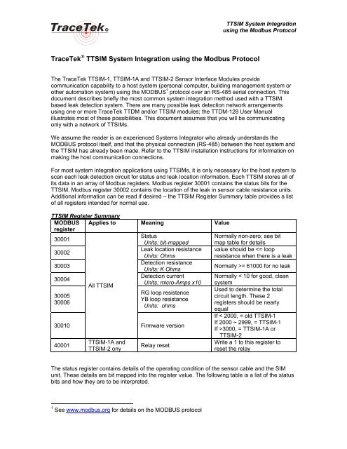
<strong>TTSIM</strong> Register Summary<br />
MODBUS Applies to Meaning Value<br />
register<br />
30001<br />
Status<br />
Normally non-zero; see bit<br />
Units: bit-mapped map table for details<br />
30002<br />
Leak location resistance value should be = 61000 for no leak<br />
Detection current<br />
Normally < 10 for good, clean<br />
30004<br />
Units: micro-Amps x10 system<br />
All <strong>TTSIM</strong><br />
Used to determine <strong>the</strong> total<br />
RG loop resistance<br />
30005<br />
circuit length. These 2<br />
YB loop resistance<br />
30006<br />
registers should be nearly<br />
Units: ohms<br />
equal<br />
If < 2000, = old <strong>TTSIM</strong>-1<br />
30010<br />
Firmware version<br />
If 2000 ~ 2999, = <strong>TTSIM</strong>-1<br />
If >3000, = <strong>TTSIM</strong>-1A or<br />
<strong>TTSIM</strong>-2<br />
40001<br />
<strong>TTSIM</strong>-1A and<br />
<strong>TTSIM</strong>-2 ony<br />
Relay reset<br />
Write a 1 to this register to<br />
reset <strong>the</strong> relay<br />
The status register contains details of <strong>the</strong> operating condition of <strong>the</strong> sensor cable and <strong>the</strong> SIM<br />
unit. These details are bit mapped into <strong>the</strong> register value. The following table is a list of <strong>the</strong> status<br />
bits and how <strong>the</strong>y are to be interpreted.<br />
1 See www.modbus.org for details on <strong>the</strong> MODBUS protocol
R<br />
<strong>TTSIM</strong> <strong>System</strong> <strong>Integration</strong><br />
<strong>using</strong> <strong>the</strong> <strong>Modbus</strong> <strong>Protocol</strong><br />
Status Register (30001) Bit Mapping<br />
Bit # Meaning<br />
Interpretation<br />
(bit value)<br />
1 (1) Leak indication<br />
0 = no leak, 1 = leak<br />
(detection resistance < leak sensitivity)<br />
2 (2)<br />
Sensor contamination<br />
(detection current > service required<br />
sensitivity)<br />
0 = cable is clean,<br />
1 = contamination (if no leak<br />
indication) or leak<br />
3 (4) Sensor loop integrity 0 = sensor OK, 1 = sensor cable break<br />
4 (8)<br />
Sensor loop balance<br />
0 = sensor OK,<br />
(RG loop YB loop)<br />
1 = cable loop imbalance<br />
5 (16)<br />
6 (32)<br />
7 (64)<br />
SIM unit program status<br />
If any of <strong>the</strong>se bits = 1, <strong>the</strong>re is a<br />
problem with <strong>the</strong> SIM unit itself.<br />
The higher order bits (bits 8 to 16) provide o<strong>the</strong>r information about <strong>the</strong> SIM itself, however <strong>the</strong>se<br />
first seven are all that is required to determine <strong>the</strong> integrity of <strong>the</strong> leak detection circuit.<br />
When a leak occurs, <strong>the</strong> location can be determined by reading <strong>the</strong> location resistance (register<br />
30002) and dividing that value by 3.900 to obtain <strong>the</strong> location in feet, or dividing by 12.796 to<br />
obtain <strong>the</strong> location in meters. To determine <strong>the</strong> total length of <strong>the</strong> circuit, divide <strong>the</strong> loop<br />
resistance (ei<strong>the</strong>r register 30005 or 30006) by 3.900 for feet, or by 12.796 for meters.<br />
To reset <strong>the</strong> alarm relay on a <strong>TTSIM</strong>-1A or <strong>TTSIM</strong>-2, write a 1 to register 40001. <strong>TTSIM</strong>-1 has no<br />
reset function. To determine <strong>the</strong> <strong>TTSIM</strong> version, read register 30010; if <strong>the</strong> value is 3000 or<br />
higher, it is a <strong>TTSIM</strong>-1A or <strong>TTSIM</strong>-2; if <strong>the</strong> value is less than 3000, it is a <strong>TTSIM</strong>-1.<br />
Each <strong>TTSIM</strong> should be scanned and tested as follows:<br />
1. read <strong>the</strong> status register (STATUS)<br />
2. test STATUS value for leak indication:<br />
LEAK if (STATUS bitand 1)=1<br />
…i.e., bit 1 is set<br />
a. if LEAK, read <strong>the</strong> location register (RLOC) and calculate <strong>the</strong> leak location:<br />
LOCATION = RLOC / 3.900 … location in feet from start of sensor<br />
-or-<br />
LOCATION =RLOC / 12.796 … location in meters from start of sensor<br />
3. test STATUS value for cable and <strong>TTSIM</strong> integrity:<br />
FAULT if (STATUS bitand 124) 0 … i.e., any one of bits 3~7 is set<br />
If desired additional details can be displayed on <strong>the</strong> host system by testing <strong>the</strong> status bits<br />
individually and providing appropriate responses. It is usually sufficient for <strong>the</strong> host system to<br />
detect an alarm in <strong>the</strong> event of a leak or a system fault.


