RayClic Unpowered Installation Instructions - California Detection ...
RayClic Unpowered Installation Instructions - California Detection ...
RayClic Unpowered Installation Instructions - California Detection ...

You also want an ePaper? Increase the reach of your titles
YUMPU automatically turns print PDFs into web optimized ePapers that Google loves.
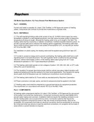
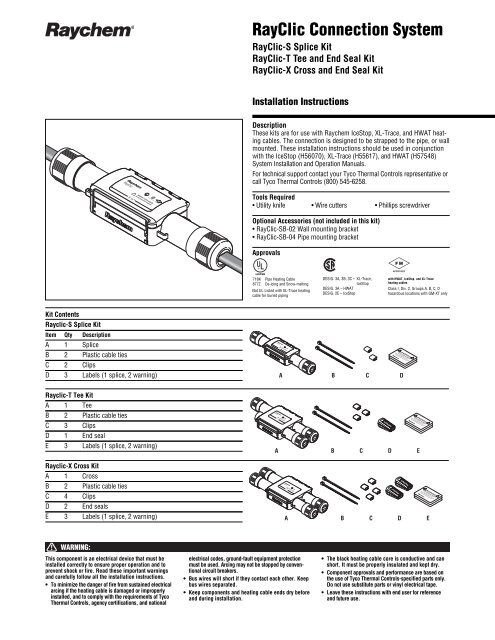
<strong>RayClic</strong> Connection System<strong>RayClic</strong>-S Splice Kit<strong>RayClic</strong>-T Tee and End Seal Kit<strong>RayClic</strong>-X Cross and End Seal Kit<strong>Installation</strong> <strong>Instructions</strong>DescriptionThese kits are for use with Raychem IceStop, XL-Trace, and HWAT heatingcables. The connection is designed to be strapped to the pipe, or wallmounted. These installation instructions should be used in conjunctionwith the IceStop (H56070), XL-Trace (H55617), and HWAT (H57548)System <strong>Installation</strong> and Operation Manuals.For technical support contact your Tyco Thermal Controls representative orcall Tyco Thermal Controls (800) 545-6258.Tools Required• Utility knife • Wire cutters • Phillips screwdriverOptional Accessories (not included in this kit)• <strong>RayClic</strong>-SB-02 Wall mounting bracket• <strong>RayClic</strong>-SB-04 Pipe mounting bracketApprovals718K Pipe Heating Cable877Z De-icing and Snow-meltingNot UL Listed with XL-Trace heatingcable for buried pipingDESIG. 3A, 3B, 3C – XL-Trace,IceStopDESIG. 3A – HWATDESIG. 2E – IceStopwith HWAT, IceStop, and XL-Traceheating cablesClass I, Div. 2, Groups A, B, C, Dhazardous locations with GM-XT onlyKit ContentsRayclic-S Splice KitItem Qty DescriptionA 1 SpliceB 2 Plastic cable tiesC 2 ClipsD 3 Labels (1 splice, 2 warning)A B C DRayclic-T Tee KitA 1 TeeB 2 Plastic cable tiesC 3 ClipsD 1 End sealE 3 Labels (1 splice, 2 warning)Rayclic-X Cross KitA 1 CrossB 2 Plastic cable tiesC 4 ClipsD 2 End sealsE 3 Labels (1 splice, 2 warning)A B C D EA B C D EWARNING:This component is an electrical device that must beinstalled correctly to ensure proper operation and toprevent shock or fire. Read these important warningsand carefully follow all the installation instructions.• To minimize the danger of fire from sustained electricalarcing if the heating cable is damaged or improperlyinstalled, and to comply with the requirements of TycoThermal Controls, agency certifications, and nationalelectrical codes, ground-fault equipment protectionmust be used. Arcing may not be stopped by conventionalcircuit breakers.• Bus wires will short if they contact each other. Keepbus wires separated.• Keep components and heating cable ends dry beforeand during installation.• The black heating cable core is conductive and canshort. It must be properly insulated and kept dry.• Component approvals and performance are based onthe use of Tyco Thermal Controls-specified parts only.Do not use substitute parts or vinyl electrical tape.• Leave these instructions with end user for referenceand future use.
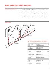
2<strong>RayClic</strong>-S, <strong>RayClic</strong>-T, <strong>RayClic</strong>-X <strong>Installation</strong> <strong>Instructions</strong>If you experience difficulty during installation, refer to the “Troubleshooting Guide” on page 7.Drip loopsFor pipe-mounted applications followsteps 1 through 10 (pages 2–4).For roof-mounted applications,follow steps 2 through 9 (pages 2–4),then turn to “Roof <strong>Installation</strong>” on page 5.Splice, Tee, and Cross <strong>Installation</strong>12• Place kit on pipe and attach with plastic cable ties.• Allow enough extra heating cable to make service loops as required.• Make sure end of heating cable is cut clean.34Do not cut throughmetal braid or innerjacket.• Score around and down the outer jacket of the heating cable3 1/8-inches from the end.• Remove the outer jacket.• Place metal clip over the base of exposed braid.3 1 /8"
<strong>RayClic</strong>-S, <strong>RayClic</strong>-T, <strong>RayClic</strong>-X <strong>Installation</strong> <strong>Instructions</strong>3IceStop and XL-TraceHWAT5AHWAT Only5BIceStop and XL-Trace Only1"• Using wire cutters, cut away 1-inch of the braid.• Pull exposed braid back over metal clip.• Pull exposed braid back over metal clip.• Using wire cutters, cut away aluminum wrap.6• Insert prepared heating cableend into connector. Push until heatingcable is fully inserted and end is visiblethrough opening in connection cover plate.
R®4<strong>RayClic</strong>-S, <strong>RayClic</strong>-T, <strong>RayClic</strong>-X <strong>Installation</strong> <strong>Instructions</strong>7 8Tighten thescrews untilthe metaltop surfaceis at thesame heightas the innerclear plasticmodule.• Securely tighten the two connection screws,alternating as they are being tightened.WARNING: Fire hazard. Loose screws can cause excessiveheating. Be sure screws are fully tightened.• Repeat steps 2 through 7 for allremaining heating cable entries.910ASplice• Close the lid and snap the lever shut.Do not force lid closed; If lid does not close, checkthe connection to ensure all screws are fully tightened.• Tighten the nuts on the heating cable entries untilgrommets are compressed.• Using glass cloth tape,attach heating cable to pipe.• Apply insulation, cladding, warninglabels and yellow splice identification label.10BTee (insulation not shown)10CCross (insulation not shown)• Using glass cloth tape,attach heating cable to pipe.• Apply insulation, cladding, warninglabels and yellow splice identification label.• Using glass cloth tape,attach heating cable to pipe.• Apply insulation, cladding, warninglabels and yellow splice identification label.
<strong>RayClic</strong>-S, <strong>RayClic</strong>-T, <strong>RayClic</strong>-X <strong>Installation</strong> <strong>Instructions</strong>5Roof <strong>Installation</strong>12<strong>RayClic</strong>-SB-02• Mount flat (wall-mounting) bracket byinstalling screws through the center holes.• Mount bracket above water line.Do not mount in gutter or where it maybe immersed in water.<strong>RayClic</strong>-S<strong>RayClic</strong>-Tand <strong>RayClic</strong>-X• Position attachment clips on mounting bracket based on typeconnector being installed.34ADrip loopsSplice• Prepare and attach heating cables as detailed insteps 2 through 9 (pages 2–4).• Attach connector to mounting bracketby pressing until it snaps into place.• Complete heating cable installation and installdrip loops as shown.• Protect heating cable from sharp edges.4BDrip loopsTee• Attach connector to mounting bracketby pressing until it snaps into place.• Complete heating cable installation andinstall drip loops as shown.• Protect heating cable from sharp edges.
6<strong>RayClic</strong>-S, <strong>RayClic</strong>-T, <strong>RayClic</strong>-X <strong>Installation</strong> <strong>Instructions</strong>End Seal <strong>Installation</strong>121"1"• Score around and down outerjacket 1-inch from the end.• Remove the outer jacket.• Do not cut or damage inner jacket.• Remove exposed braid.HWATIceStop and XL-Trace2A• Using wire cutters, cut away aluminum wrapclose to braid and outer jacket.3• Push end seal completely onto heating cable.Note: The end seal is designed to beinstalled only once; it cannot be removed from theheating cable once installed. Do not use until readyfor final installation.
<strong>RayClic</strong>-S, <strong>RayClic</strong>-T, <strong>RayClic</strong>-X <strong>Installation</strong> <strong>Instructions</strong>7Troubleshooting GuideProblemBraid clips are missing.Mounting bracket is missing.Connector does not snap onto bracket.Heating cable type not mentioned.Braid clip does not fit.Heating cable does not havealuminum wrap.Heating cable cannot beinserted into connector.Lid does not close.Heating cable cannot beinserted into end seal.Heating cable cannot be removed.SolutionThe braid clips are attached to the cardboard packing insert under the lid. The braid clips must beused to ensure a ground connection. If clips are missing or lost, call Tyco Thermal Controls at(800) 545-6258.A mounting bracket is not included in the splice, tee and cross kits. One can be ordered using one ofthe catalog numbers listed under “Optional Accessories” on the front page of these instructions whenyou place your order.The bracket has two sets of attachment clips. Fold up the four outer clips for the splice kit. Fold uponly the center clips for the tee and cross kits.<strong>RayClic</strong> components are approved for use only with Raychem HWAT, XL-Trace, and IceStop heatingcables. Do not use with other heating cables.Be sure the clip is installed on the metal braid, not on the outer jacket.Only HWAT heating cables have the aluminum wrap under the braid. Skip the aluminum wrapremoval step for XL-Trace and IceStop heating cables.Check for the following:• Outer jacket strip length is 3 1/8-inches.• Braid clip is installed on top of the metal braid, not on the outer jacket.• Braid is pulled back over braid clip.• For HWAT, 1-inch of braid is removed.• Sealing nut is loose (but not removed).• Connection screws are loose.Be sure all screws are fully tightened before closing the lid.The outer jacket must be removed from the heating cable before the end seal is installed (see the“End Seal <strong>Installation</strong>” instructions on page 6). Make sure 1-inch of outer jacket, braid, and aluminumwrap (HWAT only) are removed.The connection and end seal are designed to be installed only once; the heating cable cannot be removedonce installed. Additional <strong>RayClic</strong>-E end seals can be ordered from Tyco Thermal Controls.
8<strong>RayClic</strong>-S, <strong>RayClic</strong>-T, <strong>RayClic</strong>-X <strong>Installation</strong> <strong>Instructions</strong>Tyco, HWAT, IceStop, Raychem, <strong>RayClic</strong>, and XL-Trace are trademarks of TycoThermal Controls LLC or its affiliates.© 1995, 1998, 1999, 2003, 2004 Tyco Thermal Controls LLC INST-173 PN 473303-000 H55388 12/04Worldwide HeadquartersTyco Thermal Controls300 Constitution DriveMenlo Park, CA 94025-1164USATel (800) 545-6258Fax (800) 596-5004info@tycothermal.comwww.tycothermal.comCanadaTyco Thermal Controls250 West St.Trenton, OntarioCanada K8V 5S2Tel (800) 545-6258Fax (800) 527-5703Important: All information, including illustrations, is believed to be reliable. Users,however, should independently evaluate the suitability of each product for their particularapplication. Tyco Thermal Controls makes no warranties as to the accuracy or completenessof the information, and disclaims any liability regarding its use. Tyco ThermalControls' only obligations are those in the Tyco Thermal Controls Standard Terms andConditions of Sale for this product, and in no case will Tyco Thermal Controls or itsdistributors be liable for any incidental, indirect, or consequential damages arisingfrom the sale, resale, use, or misuse of the product. Specifications are subject tochange without notice. In addition, Tyco Thermal Controls reserves the right to makechanges—without notification to Buyer—to processing or materials that do not affectcompliance with any applicable specification.