AMC-1H Installation Instructions
AMC-1H Installation Instructions
AMC-1H Installation Instructions

Create successful ePaper yourself
Turn your PDF publications into a flip-book with our unique Google optimized e-Paper software.
R<br />
<strong>AMC</strong>-<strong>1H</strong><br />
Ambient-Sensing Thermostat<br />
for Hazardous Locations<br />
<strong>Installation</strong> <strong>Instructions</strong><br />
4.5 in. (114 mm) 4.0 in. (102 mm)<br />
4.0 in. (102 mm)<br />
Ø.28 in. (7 mm)<br />
mounting<br />
hole (4X)<br />
Terminal<br />
block<br />
1.2 in.<br />
(30 mm)<br />
DigiTrace<br />
8.0 in.<br />
(202 mm)<br />
4.0 in.<br />
(102 mm)<br />
4.5 in.<br />
(114 mm)<br />
2.0 in.<br />
(50 mm)<br />
6.6 in.<br />
(168 mm)<br />
3⁄4 in.<br />
NPT<br />
conduit<br />
entry<br />
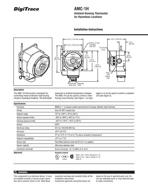
Description<br />
The <strong>AMC</strong>-<strong>1H</strong> thermostat is designed for<br />
controlling freeze-protection heat-tracing<br />
circuits in hazardous locations. The thermostat<br />
Removable<br />
knob cover<br />
Adjusting<br />
knob<br />
responds to ambient temperature changes.<br />
The <strong>AMC</strong>-<strong>1H</strong> can be used to control a heattracing<br />
circuit directly (see Figure 1 on back<br />
page) or it can be used to control a contactor<br />
coil (see Figure 2).<br />
Specifications<br />
Enclosure<br />
Entries<br />
Setpoint range<br />
Sensor exposure limits<br />
Housing exposure limits<br />
Switch<br />
Electrical rating<br />
Accuracy<br />
Deadband<br />
Setpoint repeatability<br />
Sensor type<br />
Sensor material<br />
NEMA 4, 7, 9, lacquer-coated cast-aluminum housing, stainless-steel hardware<br />
One 3/4" NPT conduit hub<br />
15°F to 140°F (–9°C to 60°C)<br />
–40°F to 160°F (–40°C to 71°C)<br />
–40°F to 140°F (–40°C to 60°C)<br />
SPDT<br />
22 A at 125/250/480 Vac<br />
±6°F (±3.3°C)<br />
2°F to 12°F (1.1°C to 6.7°C) above actuation temperature<br />
±3°F (±1.7°C)<br />
Fluid-filled (silicone) bulb and 9 ft (2.7 m) capillary<br />
300 series stainless steel<br />
Connection terminals Screw terminals, 10–14 AWG (2–5 mm 2 )<br />
Approvals<br />
Hazardous locations<br />
Class I, Div. 1 and 2, Groups B, C, D<br />
Class II, Div. 1 and 2, Groups E, F, G<br />
Class III<br />
WARNING:<br />
This component is an electrical device. It must<br />
be installed correctly to ensure proper operation<br />
and to prevent shock or fire. Read these<br />
important warnings and carefully follow all the<br />
installation instructions.<br />
Component approvals and performance are<br />
based on the use of specified parts only. Do<br />
not use substitute parts or vinyl electrical tape<br />
to make connections.
2<br />
<strong>AMC</strong>-<strong>1H</strong> <strong>Installation</strong> <strong>Instructions</strong><br />
Installing the Thermostat 1. Verify that the thermostat is suitable for<br />
the area where it is to be installed.<br />
Conduit<br />
drain<br />
2. Check the line voltage and the heat-tracing<br />
load to ensure that the thermostat<br />
ratings are not exceeded.<br />
3. Mount the unit in a position that prevents<br />
condensation from draining into<br />
the enclosure from the connecting conduit<br />
(see diagram at left).<br />
Positioning 4. Mount ambient-sensing units in the area<br />
exposed to the coldest temperature and<br />
the most wind. Do not mount on the<br />
side of a warm building or in a location<br />
that is exposed to warm air currents or<br />
direct sunlight.<br />
Setting and Adjusting 5. Set the thermostat dial to the desired<br />
temperature and finish wiring.<br />
Wiring<br />
GFEPD<br />
GFEPD<br />
G<br />
Ø Ø<br />
or<br />
N Ø<br />
208-V or 240-V supply – 240-V heater<br />
120-V supply – 120-V heater<br />
277-V supply – 240-V heater<br />
G N A N B N C<br />
Ø A<br />
Ø B<br />
Ø C<br />
120-V supply – 120-V heater or<br />
277-V supply – 240-V heater<br />
Braid<br />
G<br />
C NO NC<br />
Power<br />
connection<br />
Heating<br />
Cable<br />
Figure 1. Heat-tracing control<br />
Control<br />
thermostat<br />
Braid<br />
Heating<br />
cable A<br />
Heating<br />
cable B<br />
Heating<br />
cable C<br />
Figure 2. Controlling a contactor<br />
For switching heat-tracing loads greater than 22 A<br />
or switching multiple heat-tracing circuits.<br />
C<br />
120-V or<br />
277-V<br />
coil<br />
NC<br />
NC<br />
NO<br />
NO<br />
C<br />
C<br />
Control<br />
thermostat<br />
© 1995, 2001 Tyco Thermal Controls LLC Printed in USA PN 174517 H56911 10/01<br />
Worldwide Headquarters<br />
Tyco Thermal Controls<br />
300 Constitution Drive<br />
Menlo Park, CA 94025-1164<br />
USA<br />
Tel (800) 545-6258<br />
Fax (650) 474-7517<br />
Fax-on-Demand (800) 329-4494<br />
info@tycothermal.com<br />
www.tycothermal.com<br />
Important: All information, including illustrations, is believed to be reliable. Users, however, should<br />
independently evaluate the suitability of each product for their particular application. Tyco Thermal Controls<br />
makes no warranties as to the accuracy or completeness of the information, and disclaims any liability regarding<br />
its use. Tyco Thermal Controls' only obligations are those in the Tyco Thermal Controls Standard Terms and<br />
Conditions of Sale for this product, and in no case will Tyco Thermal Controls or its distributors be liable for<br />
any incidental, indirect, or consequential damages arising from the sale, resale, use, or misuse of the product.<br />
Specifications are subject to change without notice. In addition, Tyco Thermal Controls reserves the right to<br />
make changes—without notification to Buyer—to processing or materials that do not affect compliance with any<br />
applicable specification.