I.P.S. Pressure/Irrigation (P.I.P) Installation Guide - JM Eagle
I.P.S. Pressure/Irrigation (P.I.P) Installation Guide - JM Eagle
I.P.S. Pressure/Irrigation (P.I.P) Installation Guide - JM Eagle

You also want an ePaper? Increase the reach of your titles
YUMPU automatically turns print PDFs into web optimized ePapers that Google loves.
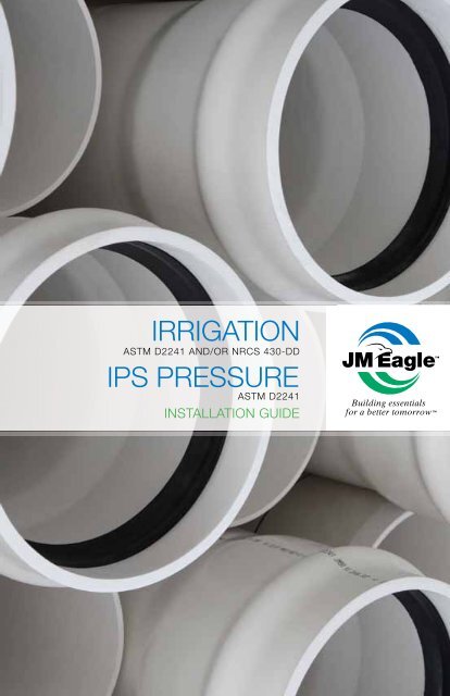
IRRIGATION<br />
ASTm D2241 AND/OR NRcS 430-DD<br />
IPS PRESSURE<br />
ASTm D2241<br />
INSTALLATION GUIDE<br />
Building essentials<br />
for a better tomorrow
WARNING<br />
RUPTURE HAZARD<br />
ImPROPER INSTALLATION OR mISUSE Of TAPPING TOOLS mAy cAUSE<br />
PIPES UNDER hIGh PRESSURE TO RUPTURE AND RESULT IN hIGh<br />
vELOcITy AIRbORNE fRAGmENTATION LEADING TO SERIOUS INJURIES<br />
AND/OR DEATh.<br />
• BEFOrE anD DUring inSTallaTiOn, alWaYS:<br />
• cONSULT AND fOLLOw ThE fULL vERSION Of ThE PRODUcT<br />
INSTALLATION GUIDE<br />
• cLOSELy fOLLOw JOb SPEcIfIcATIONS<br />
• USE PROTEcTIvE GEAR AND EQUIPmENT<br />
• BEFOrE anD DUring TaPPing, alWaYS:<br />
• cONSULT AND fOLLOw UNI-bELL ® PUbLIcATION UNI-PUb-08-07,<br />
“TAPPING GUIDE fOR Pvc PRESSURE PIPE.”<br />
• USE ThE cORREcT TAPPING TOOLS<br />
• bLEED AIR fROm PIPES AT hIGh SPOT bEfORE TAPPING<br />
• USE PROTEcTIvE GEAR AND EQUIPmENT<br />
PLEASE cONTAcT Jm EAGLE PRODUcT ASSURANcE AT (800) 621-4404<br />
TO ObTAIN fULL vERSION Of ThE APPROPRIATE INSTALLATION GUIDE<br />
OR fOR fURThER ASSISTANcE.
IRRIGATION &<br />
IPS PRESSURE<br />
cONTENTS<br />
1.0<br />
REcEIvING AND hANDLING PIPE ShIPmENTS . . . . . . . . . . . . . . . . . . . 8<br />
1.1 INSPEcTION . . . . . . . . . . . . . . . . . . . . . . . . . . . . . . . . . . . . . . . . . . . . 8<br />
1.2 UNLOADING . . . . . . . . . . . . . . . . . . . . . . . . . . . . . . . . . . . . . . . . . . . . 9<br />
1.3 cOLD-wEAThER hANDLING . . . . . . . . . . . . . . . . . . . . . . . . . . . . . . 11<br />
1.4 STOckPILES . . . . . . . . . . . . . . . . . . . . . . . . . . . . . . . . . . . . . . . . . . . 11<br />
1.5 GASkET cARE . . . . . . . . . . . . . . . . . . . . . . . . . . . . . . . . . . . . . . . . . 12<br />
1.6 LOADING TRANSfER TRUckS . . . . . . . . . . . . . . . . . . . . . . . . . . . . 12<br />
1.7 DISTRIbUTING ALONG ThE TRENch . . . . . . . . . . . . . . . . . . . . . . . . 13<br />
2.0<br />
TRENch cONSTRUcTION . . . . . . . . . . . . . . . . . . . . . . . . . . . . . . . . . . . 13<br />
2.1 wORkING AhEAD Of ThE PIPE LAyING cREw . . . . . . . . . . . . . . . 13<br />
2.2 cURvES IN ThE TRENch . . . . . . . . . . . . . . . . . . . . . . . . . . . . . . . . 14<br />
2.2.1 1.5 INch-12 INch IPS PRESSURE AND IRRIGATION . . . . . . 14<br />
2.2.2 14 INch AND LARGER PIPE . . . . . . . . . . . . . . . . . . . . . . . . . 15<br />
3.0<br />
2.3<br />
TRENch wIDThS . . . . . . . . . . . . . . . . . . . . . . . . . . . . . . . . . . . . . . . 16<br />
2.4 TRENch DEPThS . . . . . . . . . . . . . . . . . . . . . . . . . . . . . . . . . . . . . . . 17<br />
2.5 PLANNING fOR ThRUSTING . . . . . . . . . . . . . . . . . . . . . . . . . . . . . . 18<br />
2.6 PREPARATION Of TRENch bOTTOm . . . . . . . . . . . . . . . . . . . . . . . 18<br />
PIPELINE cONSTRUcTION . . . . . . . . . . . . . . . . . . . . . . . . . . . . . . . . . . 19<br />
3.1 INSPEcTION . . . . . . . . . . . . . . . . . . . . . . . . . . . . . . . . . . . . . . . . . . . 19<br />
3.2 LOwERING PIPE AND AccESSORIES INTO TRENch . . . . . . . . . . . 19<br />
3.3 ASSEmbLy Of Jm EAGLE<br />
Pvc PIPE . . . . . . . . . . . . . . . . . . . . . . . 19
3.4 ASSEmbLy INSTRUcTIONS . . . . . . . . . . . . . . . . . . . . . . . . . . . . . 20<br />
3.5 cUTTING . . . . . . . . . . . . . . . . . . . . . . . . . . . . . . . . . . . . . . . . . . . . 23<br />
3.6 bEvELING . . . . . . . . . . . . . . . . . . . . . . . . . . . . . . . . . . . . . . . . . . . 23<br />
3.7 LOcATING REfERENcE mARk . . . . . . . . . . . . . . . . . . . . . . . . . . . 23<br />
3.8 ASSEmbLy AT fITTINGS AND ADAPTORS . . . . . . . . . . . . . . . . . . 24<br />
3.9 ThRUST bLOckING AND ANchORAGE AT fITTINGS . . . . . . . . . 24<br />
3.9.1 DETERmINING SIzE AND TyPE Of ThRUST bLOckING . . . 25<br />
3.9.2 UPwARD ThRUSTS AT fITTINGS . . . . . . . . . . . . . . . . . . . . 28<br />
3.9.3 ANchORAGE Of PIPE ON SLOPES . . . . . . . . . . . . . . . . . . 28<br />
3.9.4 ANchORAGE Of vALvES IN ThE LINE . . . . . . . . . . . . . . . . 28<br />
3.9.5 cONSTRUcTION Of ThRUST bAckING . . . . . . . . . . . . . . . 29<br />
3.10 ThRUST-RESTRAINT JOINTS . . . . . . . . . . . . . . . . . . . . . . . . . . . 29<br />
3.11 SERvIcE cONNEcTIONS . . . . . . . . . . . . . . . . . . . . . . . . . . . . . . 30<br />
4.0<br />
3.11.1 SADDLES . . . . . . . . . . . . . . . . . . . . . . . . . . . . . . . . . . . . . . 30<br />
PIPE EmbEDmENT . . . . . . . . . . . . . . . . . . . . . . . . . . . . . . . . . . . . . . . . 30<br />
4.1 bEDDING . . . . . . . . . . . . . . . . . . . . . . . . . . . . . . . . . . . . . . . . . . . . 31<br />
4.2 bAckfILLING AND TAmPING . . . . . . . . . . . . . . . . . . . . . . . . . . . . 31<br />
4.2.1 hAUNchING AND INITIAL bAckfILL . . . . . . . . . . . . . . . . . 31<br />
4.3 cOmPLETING ThE bAckfILL . . . . . . . . . . . . . . . . . . . . . . . . . . . . 33<br />
4.3.1 fINAL bAckfILL . . . . . . . . . . . . . . . . . . . . . . . . . . . . . . . . . 33<br />
4.4 cOmPAcTION mEThODS . . . . . . . . . . . . . . . . . . . . . . . . . . . . . . 34<br />
4.4.1 TAmPING bARS . . . . . . . . . . . . . . . . . . . . . . . . . . . . . . . . . 34<br />
4.4.2 mEchANIcAL TAmPERS . . . . . . . . . . . . . . . . . . . . . . . . . . 35<br />
4.4.3 fLOOD OR wATER TAmPING . . . . . . . . . . . . . . . . . . . . . . . 35<br />
4.4.4 wATER-JETTING . . . . . . . . . . . . . . . . . . . . . . . . . . . . . . . . 35<br />
4.4.5 ShEETING AND TRENch bOXES . . . . . . . . . . . . . . . . . . . 36
5.0 PIPE TESTING AND REPAIR . . . . . . . . . . . . . . . . . . . . . . . . . . . . . . . . . 36<br />
5.1 PIPE DEfLEcTION . . . . . . . . . . . . . . . . . . . . . . . . . . . . . . . . . . . . . . 36<br />
5.1.1 DEfLEcTION TESTING . . . . . . . . . . . . . . . . . . . . . . . . . . . . . . 37<br />
5.2 TESTING wATER PIPE . . . . . . . . . . . . . . . . . . . . . . . . . . . . . . . . . . . 37<br />
5.2.1 fILLING ThE LINE . . . . . . . . . . . . . . . . . . . . . . . . . . . . . . . . . . 38<br />
5.2.2 RELIEvING AIR fROm ThE LINE . . . . . . . . . . . . . . . . . . . . . . 40<br />
5.3 PRESSURE-STRENGTh TESTS . . . . . . . . . . . . . . . . . . . . . . . . . . . . 40<br />
5.4 mAkING LEAkAGE TESTS . . . . . . . . . . . . . . . . . . . . . . . . . . . . . . . . 41<br />
5.5 mAkING REPAIRS TO DAmAGED PIPELINES . . . . . . . . . . . . . . . . . 42<br />
APPENDIX 1 . . . . . . . . . . . . . . . . . . . . . . . . . . . . . . . . . . . . . . . . 44
The physical (or chemical) properties of <strong>JM</strong> <strong>Eagle</strong> IPS <strong>Pressure</strong> and<br />
<strong>Irrigation</strong> Pipe presented in this booklet, represent typical values<br />
obtained in accordance with accepted test methods and are subject<br />
to normal manufacturing variations. They are supplied as a technical<br />
service and are subject to change without notice. Check with<br />
<strong>JM</strong> <strong>Eagle</strong> Product Assurance to ensure current information.<br />
How This <strong>Guide</strong> Can Help You<br />
This booklet was written especially for the installer and those who direct<br />
actual handling and installation of <strong>JM</strong> <strong>Eagle</strong> IPS <strong>Pressure</strong> and <strong>Irrigation</strong><br />
Pipe. This guide should be used in conjunction with the following industryaccepted<br />
installation and testing practices that are applicable. This document<br />
should not be considered a full guide or manual in lieu of:<br />
1. ASTM D2774-04 (or later) “Underground <strong>Installation</strong> of Thermoplastic<br />
<strong>Pressure</strong> Piping.”<br />
2. ASTM F690-86 (2003) (or later) “Underground <strong>Installation</strong> of Thermoplastic<br />
<strong>Pressure</strong> Piping <strong>Irrigation</strong> Systems.”<br />
3. ASTM F1668-96 (2002) (or later) “Construction of Buried Plastic Pipe.”<br />
4. ASTM F645-04 (or later) “Selection, Design, and <strong>Installation</strong> of Thermoplastic<br />
Water-<strong>Pressure</strong> Piping Systems.”<br />
5. ASTM D2321-05 (or later) “Underground <strong>Installation</strong> of Thermoplastic<br />
Pipe for Sewers and Other Gravity-Flow Applications.”<br />
6. AWWA C605 “Underground <strong>Installation</strong> of Polyvinyl Chloride (PVC)<br />
<strong>Pressure</strong> Pipe and Fittings for Water.”<br />
7. AWWA C651 “Disinfecting Water Mains.”<br />
8. AWWA M23 “PVC Pipe – Design and <strong>Installation</strong>.”<br />
9. Uni-Bell ® UNI-PUB-09 “<strong>Installation</strong> <strong>Guide</strong> for PVC <strong>Pressure</strong> Pipe.”<br />
4 IRRIGATION & I.P.S. PRESSURE INSTALLATION GUIDE
10. Uni-Bell ® UNI-TR-6 “PVC Force Main Design.”<br />
11. Uni-Bell ® UNI-TR-7 “Thermoplastic <strong>Pressure</strong> Pipe Design and Selection.”<br />
This guide is meant as an explanatory supplement to the materials above<br />
on how to install <strong>JM</strong> <strong>Eagle</strong> IPS <strong>Pressure</strong> and <strong>Irrigation</strong> Pipe under normal<br />
conditions so as to comply with Standard <strong>JM</strong> <strong>Eagle</strong> Laying Specifications.<br />
Any discrepancies between the above standards and the written information<br />
contained herein should be brought to the attention of <strong>JM</strong> <strong>Eagle</strong> Product<br />
Assurance immediately for resolution by <strong>JM</strong> <strong>Eagle</strong> , prior to any actions by<br />
either contractor, engineer or municipality.<br />
This guide is not intended to supply design information nor to assume the responsibility<br />
of the engineer (or other customer representative) in establishing<br />
procedures best suited to individual job conditions so as to attain satisfactory<br />
performance.<br />
Engineers, superintendents, contractors, foremen and laying crews will find<br />
much to guide them in the following specifications. This booklet will also be<br />
of help in determining pipe needs when ordering.<br />
* For Solvent Weld assembly instructions, refer to <strong>JM</strong> <strong>Eagle</strong> Publication<br />
<strong>JM</strong>E-07B, “Solvent Weld and Conduit <strong>Installation</strong> <strong>Guide</strong>.”<br />
IRRIGATION & I.P.S. PRESSURE INSTALLATION GUIDE<br />
5
Warranty<br />
J-M Manufacturing Company Inc. (<strong>JM</strong> <strong>Eagle</strong> ) warrants that its standard<br />
polyvinyl chloride (PVC), polyethylene (PE), conduit/plumbing/solvent weld<br />
and Acrylonitrile-Butadiene-Styrene (ABS) pipe products (“Products”) are<br />
manufactured in accordance with applicable industry specifications referenced<br />
on the Product and are free from defects in workmanship and materials.<br />
Every claim under this warranty shall be void unless in writing and<br />
received by <strong>JM</strong> <strong>Eagle</strong> within 30 days of the date the defect was discovered,<br />
and within one (1) year of the date of shipment from the <strong>JM</strong> <strong>Eagle</strong> <br />
plant. Claims for Product appearance defects, such as sun-bleached pipe<br />
etc., however, must be made within thirty (30) days of the date of the shipment<br />
from the <strong>JM</strong> <strong>Eagle</strong> plant. This warranty specifically excludes any Products<br />
allowed to become sun-bleached after shipment from the <strong>JM</strong> <strong>Eagle</strong> <br />
plant. Proof of purchase with the date thereof must be presented to the<br />
satisfaction of <strong>JM</strong> <strong>Eagle</strong> , with any claim made pursuant to this warranty.<br />
<strong>JM</strong> <strong>Eagle</strong> must first be given an opportunity to inspect the alleged defective<br />
Products in order to determine if it meets applicable industry standards,<br />
if the handling and installation have been satisfactorily performed in<br />
accordance with <strong>JM</strong> <strong>Eagle</strong> recommended practices and if operating conditions<br />
are within standards. Written permission and/or a Return Goods<br />
Authorization (RGA) must be obtained along with instructions for return shipment<br />
to <strong>JM</strong> <strong>Eagle</strong> of any Products claimed to be defective.<br />
The limited and exclusive remedy for breach of this Limited Warranty shall<br />
be, at <strong>JM</strong> <strong>Eagle</strong>’s sole discretion, the replacement of the same type, size and<br />
like quantity of non-defective Product, or credits, offsets or combination of<br />
thereof, for the wholesale purchase price of the defective unit.<br />
This Limited Warranty does not apply for any Product failures caused by user’s<br />
flawed designs or specifications, unsatisfactory applications, improper<br />
installations, use in conjunction with incompatible materials, contact with<br />
aggressive chemical agents, freezing or overheating of liquids in the Product<br />
and any other misuse causes not listed here. This Limited Warranty also excludes<br />
failure or damage caused by fire stopping materials, tread sealants,<br />
plasticized vinyl products or damage caused by the fault or negligence of<br />
anyone other than <strong>JM</strong> <strong>Eagle</strong> , or any other act or event beyond the control<br />
of <strong>JM</strong> <strong>Eagle</strong> .<br />
6 IRRIGATION & I.P.S. PRESSURE INSTALLATION GUIDE
<strong>JM</strong> <strong>Eagle</strong>’s liability shall not, at any time, exceed the actual wholesale purchase<br />
price of the Product. The warranties in this document are the only<br />
warranties applicable to the Product and there are no other warranties, expressed<br />
or implied. This Limited Warranty specifically excludes any liability<br />
for general damages, consequential or incidental damages, including<br />
without limitation, costs incurred from removal, reinstallation, or other expenses<br />
resulting from any defect. IMPLIED WARRANTIES OF MERCHANT-<br />
ABILITY OR FITNESS FOR A PARTICULAR PURPOSE ARE SPECIFICALLY<br />
DISCLAIMED AND <strong>JM</strong> <strong>Eagle</strong> SHALL NOT BE LIABLE IN THIS RESPECT<br />
NOTWITHSTANDING <strong>JM</strong> <strong>Eagle</strong>’s ACTUAL KNOWLEDGE THE PROD-<br />
UCT’S INTENDED USE.<br />
<strong>JM</strong> <strong>Eagle</strong>’s Products should be used in accordance with standards set forth<br />
by local plumbing and building laws, codes or regulations and the applicable<br />
standards. Failure to adhere to these standards shall void this Limited<br />
Warranty. Products sold by <strong>JM</strong> <strong>Eagle</strong> that are manufactured by others are<br />
warranted only to the extent and limits of the warranty of the manufacturer.<br />
No statement, conduct or description by <strong>JM</strong> <strong>Eagle</strong> or its representative,<br />
in addition to or beyond this Limited Warranty, shall constitute a warranty.<br />
This Limited Warranty may only be modified in writing signed by an officer<br />
of <strong>JM</strong> <strong>Eagle</strong> .<br />
IRRIGATION & I.P.S. PRESSURE INSTALLATION GUIDE<br />
7
1.0 Receiving and Handling Pipe ShipmentS<br />
Figure 1<br />
1.1 Inspection<br />
Each pipe shipment shall be inspected with care upon arrival. Each pipe<br />
shipment is carefully loaded at the factory using methods acceptable to the<br />
carrier. The carrier is then responsible for delivering the pipe as received<br />
from <strong>JM</strong> <strong>Eagle</strong> . All shipments include an adequate amount of lubricant for<br />
the pipe and a short form installation guide. IT IS THE RESPONSIBILTY OF<br />
THE RECEIVER TO MAKE CERTAIN THERE HAS BEEN NO LOSS OR DAM-<br />
AGE (including smoke) UPON ARRIVAL.<br />
Check the materials, pipe, gaskets and fittings received against the bill of<br />
lading (tally sheet that accompanies every shipment) in accordance with the<br />
general guidelines below, reporting any error or damage to the transportation<br />
company representative and have proper notation made on the delivery<br />
receipt and signed by the driver. Present the claim in accordance with the<br />
carrier’s instructions. Do not dispose of any damaged material. The carrier<br />
will advise you of the procedure to follow in order to procure samples and<br />
report the incident.<br />
1. MAKE OVERALL EXAMINATION OF THE LOAD. If the load is intact,<br />
ordinary inspection while unloading should be enough to make sure<br />
pipe has arrived in good condition.<br />
8 IRRIGATION & I.P.S. PRESSURE INSTALLATION GUIDE
2. IF LOAD HAS SHIFTED OR SHOWS ROUGH TREATMENT, THEN<br />
EACH PIECE MUST BE CAREFULLY INSPECTED FOR DAMAGE.<br />
3. CHECK THE TOTAL QUANTITIES OF EACH ITEM AGAINST THE<br />
TALLY SHEET (pipe, fittings, lubricant, etc.).<br />
4. ANY DAMAGED OR MISSING ITEMS MUST BE NOTED ON THE<br />
DELIVERY RECEIPT AND RETURNED TO THE TRANSPORTATION<br />
COMPANY.<br />
5. NOTIFY CARRIER IMMEDIATELY AND MAKE CLAIM IN ACCOR-<br />
DANCE WITH THEIR INSTRUCTIONS.<br />
6. DO NOT DISPOSE OF ANY DAMAGED MATERIAL. Carrier will notify<br />
you of the procedure to follow.<br />
7. SHORTAGES AND DAMAGED MATERIALS ARE NOT AUTOMATICAL-<br />
LY RESHIPPED. If replacement material is needed reorder through<br />
your distributor and make them aware of the claim.<br />
1.2 Unloading<br />
Figure 2<br />
<strong>JM</strong> <strong>Eagle</strong> IPS <strong>Pressure</strong> and <strong>Irrigation</strong> Pipe is lightweight and may be unloaded<br />
by 1. Hand, either by passing over the side or off the truck ends.<br />
Sliding one length on another is standard practice in unloading PVC pipe,<br />
but lengths in the bottom layer should be lifted off of the rough surface of the<br />
truck body to avoid abrasion. 2. Compact shipping units (palletized bundles<br />
in a wood frame) are used to ship large orders of pipe. Conventional forklifts<br />
can unload these units quickly and easily. Care shall be exercised to avoid<br />
IRRIGATION & I.P.S. PRESSURE INSTALLATION GUIDE<br />
9
impact or contact between the forks and the pipe. The means by which<br />
<strong>JM</strong> <strong>Eagle</strong> IPS <strong>Pressure</strong> and <strong>Irrigation</strong> Pipe are unloaded in the field is the<br />
decision and responsibility of the customer. Preferred unloading is in units<br />
using mechanical equipment such as forklifts, cherry pickers or front-end<br />
loaders with adequate forks and trained, competent operators. When unloading<br />
units, the following instructions should be carefully followed. Remove<br />
only one unit at a time.<br />
1. Remove restraints from the top unit loads. These may be either tiedown<br />
straps, ropes, or chains with protection.<br />
2. If there are wooden boards across the top and down the sides of the<br />
load that are not part of pipe packaging, remove them.<br />
3. Use a forklift (or front-end loader equipped with forks) to remove each<br />
top unit one at a time from the truck. Remove back units first. Do not<br />
run the forks too far under the unit as fork ends striking adjacent units<br />
may cause damage or push units off the opposite side of the truck.<br />
Do not let forks rub the underside of pipe to avoid abrasion.<br />
4. If a forklift is not available, a crane or front end loader may be used<br />
to unload the pipe. We recommend employing a spreader bar with<br />
synthetic straps rated for the load. The straps should be placed approximately<br />
8 feet apart and looped under the load. Cables maybe be<br />
used in place of synthetic straps if they are protected by a rubber hose<br />
sleeve to prevent damage to the pipe.<br />
5. DO NOT:<br />
a) Handle units with chains or single cables.<br />
b) Attach cables to unit frames for lifting.<br />
6. During the removal and handling, be sure that the units do not strike<br />
anything. Severe impact could damage the pipe (particularly during<br />
cold weather).<br />
7. Units should be stored and placed on level ground. Units should be<br />
protected by dunnage in the same way they were protected while<br />
loaded on the truck. The dunnage must support the weight of all units<br />
so that pipe lengths do not carry the weight of the unit loaded above<br />
them. Units should not be stacked more than 2 high.<br />
8. To unload lower units, repeat the above unloading process (items 1<br />
through 7).<br />
10 IRRIGATION & I.P.S. PRESSURE INSTALLATION GUIDE
Warning: PVC pipe, though lighter than other material, is still heavy and<br />
may be dangerous if not handled properly. Not adhering to the above instructions<br />
at left may result in serious injury to pipe, property and/or people.<br />
Do not stand or climb on units. Stand clear of pipe during unloading.<br />
NOTICE: Pipe at the bottom of a stack may become out-of-round due to<br />
the weight of the material above it. At normal application temperatures this<br />
corrects itself soon after the load is removed due to the property of elastic<br />
memory. Under freezing conditions, this recovery to full initial roundness may<br />
take several hours.<br />
1.3 Cold-Weather Handling<br />
As the temperature approaches and drops below freezing, the flexibility and<br />
impact resistance of PVC pipe is reduced. Extra care should be used in<br />
handling during cold weather to avoid any type of impact to the pipe to<br />
prevent damage.<br />
1.4 Stockpiles<br />
Store pipe on a flat surface so as to support the barrel evenly, with bell ends<br />
overhanging. If mechanical equipment is being used for handling, the unit<br />
bearing pieces provide an excellent base. If unloading by hand, secure two<br />
timbers for a base. Set them on a flat area spaced the same as a factory<br />
load. Nail chock blocks at each end. Build up the stockpile in the same manner,<br />
as it was stacked for shipment, transferring dunnage and chock blocks<br />
from load to stockpile. Store random lengths separately where they will be<br />
readily available. Individual lengths of pipe should be stacked in piles no<br />
higher than 5 feet.<br />
It should be noted that when PVC pipe is stored outside and exposed to<br />
prolonged periods of sunlight, an obvious discoloration or UV degradation<br />
of pipe could occur. Based on the 24-month weathering study, the performance<br />
of PVC pipe was equally impressive. No significant changes in tensile<br />
strength at yield was observed. Reductions in impact strength were apparent<br />
after two years of exposure to weathering and ultra violet radiation.<br />
However, considering PVC pipe’s high initial-impact strength, the reductions<br />
IRRIGATION & I.P.S. PRESSURE INSTALLATION GUIDE<br />
11
were not significant enough to warrant concern. Pipe breakage due to impact<br />
loads encountered during normal handling and installation is not a problem<br />
with PVC pipe. This UV degradation does not continue after the pipe is<br />
removed from UV exposure.<br />
A method of protecting pipe during long exposures (several months) to sunlight<br />
is to cover it with canvas or other opaque material. Clear plastic sheets<br />
are not satisfactory. Allow for adequate air circulation between the cover and<br />
the pipe. This will prevent heat build-up and possible dimensional distortion.<br />
1.5 Gasket Care<br />
All <strong>JM</strong> <strong>Eagle</strong> PVC pipe is manufactured with factory-installed gaskets. These<br />
gaskets cannot be easily removed or replaced outside of the factory. Keep<br />
them clean, away from oil, grease, excessive heat and electric motors, which<br />
produce ozone. It is advisable to keep gaskets protected from direct sunlight<br />
and temperature changes in order to avoid cracking in prolonged exposure<br />
for optimal performance. <strong>JM</strong> <strong>Eagle</strong> provides a gasket that is approved for<br />
water service with its standard product. Special gasket types may be available<br />
for applications where oil resistance is required. Be sure the correct ring<br />
is ordered. See Section 3.4 for further information.<br />
1.6 Loading Transfer Trucks<br />
Use trucks with long bodies so that pipe lengths do not over-hang more<br />
than 2 feet. Make certain truck bed is smooth, without cross-strapping, bolt<br />
heads, or other protrusions that could damage the pipe.<br />
Place the first layer carefully with the bell ends overhanging. Avoid sliding the<br />
pipe and abrading it. Subsequent layers can be slid into place. All bell ends<br />
should overhang the layer below.<br />
Short body trucks may be used if fitted with racks that properly support the<br />
pipe in the horizontal position. The rack shall support the pipe with supports<br />
spaced every 3 feet or less along the pipe lengths. Pad the contact areas to<br />
avoid damage to the pipe.<br />
12 IRRIGATION & I.P.S. PRESSURE INSTALLATION GUIDE
1.7 Distributing Along the Trench<br />
In stringing out pipe, keep these points in mind:<br />
1. Line pipe as near to the trench as possible to avoid excessive handling.<br />
(Bell direction doesn’t affect flow or hydraulic coefficients.)<br />
2. If the trench is open, it is advisable to string pipe on the side away<br />
from excavated earth wherever possible, so that the pipe can be<br />
moved easily to the edge of the trench for lowering into position.<br />
3. If the trench is not yet open, find out which side the excavated earth<br />
will be thrown, then string out on the opposite side (leave room for<br />
the excavator).<br />
4. Place the pipe so as to protect it from traffic and heavy equipment.<br />
Also, safeguard it from the effects of any blasting that may be done.<br />
2.0 Trench Construction<br />
2.1 Working Ahead of the Pipe Laying Crew<br />
Where soil and groundwater conditions permit, long stretches of trench can<br />
be opened ahead of pipe laying, so as to take full advantage of the easy<br />
handling and speed of assembly of <strong>JM</strong> <strong>Eagle</strong> IPS <strong>Pressure</strong> and <strong>Irrigation</strong><br />
Pipe with elastomeric joints. However, as a general rule for most jobs, do not<br />
open the trench too far ahead of pipe laying. Avoiding these long stretches of<br />
opened trench may help with the economy of the project because:<br />
1. It may reduce or even eliminate pumping or sheeting.<br />
2. It minimizes the possibility of flooding the trench.<br />
3. It reduces caving caused by ground water.<br />
4. It helps avoid frozen trench bottom and backfill.<br />
5. It reduces hazards to traffic and workers.<br />
On most jobs, it will be desirable to keep excavating, pipe laying and backfilling<br />
close together.<br />
IRRIGATION & I.P.S. PRESSURE INSTALLATION GUIDE<br />
13
2.2 Curves in the Trench<br />
2.2.1 1.5-inch to 12-inch IPS <strong>Pressure</strong> and irrigation<br />
The trench may be curved to change direction or avoid obstructions within<br />
the limits of the curvature of the pipe as shown in Table 1.<br />
PIPE SIZE<br />
(inches)<br />
MINIMUM<br />
RADIUS<br />
(feet)<br />
OFFSET<br />
(in)<br />
PIPE SIZE<br />
(inches)<br />
MINIMUM<br />
RADIUS<br />
(feet)<br />
OFFSET<br />
(in)<br />
1.5 37.5 65.56 5 125 19.24<br />
2 50 48.65 6 150 16.02<br />
2.5 62.5 38.73 8 200 12.01<br />
3 75 32.19 10 250 9.61<br />
4 100 24.08 12 300 8.00<br />
Table 1 (IPS <strong>Pressure</strong> and <strong>Irrigation</strong> Pipe)<br />
The line may be assembled above ground, in a straight line, and then curved<br />
when laid in the trench. All curvature results from the bending of the pipe<br />
lengths. There is no deflection allowed at the joint on sizes 12 inches and<br />
smaller. The approximate force per 20 foot length in pounds to accomplish<br />
these curvatures is (based on SDR):<br />
PIPE SIZE<br />
(inches)<br />
SDR 41 SDR 32.5 SDR 26 SDR 21 SDR 17<br />
4 8.06 9.94 12.14 14.58 17.40<br />
6 25.20 31.10 37.98 45.67 54.10<br />
8 54.09 66.92 81.77 98.23 116.68<br />
10 104.51 129.48 157.50 189.30 225.85<br />
12 172.34 212.93 259.72 311.94 372.17<br />
Table 2A (IPS <strong>Pressure</strong> Pipe)<br />
14 IRRIGATION & I.P.S. PRESSURE INSTALLATION GUIDE
PIPE SIZE<br />
(inches)<br />
SDR 51 SDR 41 SDR 35 SDR 32.5<br />
6 14.87 18.70 21.36 22.92<br />
8 35.53 43.24 49.80 53.46<br />
10 68.64 85.21 98.36 105.51<br />
12 119.80 145.81 168.96 181.31<br />
Table 2B (<strong>Irrigation</strong> Pipe)<br />
NOTICE: Mechanical means should not be employed to accomplish these<br />
radii. It is the intent that the workers should accomplish this manually in<br />
the trench. ON 1.5-inch to 12-inch PIPE, THE CURVE SHOULD BE AC-<br />
COMPLISHED BY BENDING THE PIPE RATHER THAN BY DEFLECTING<br />
THE JOINTS. THERE SHALL BE NO DEFLECTION IN THE JOINTS UPON<br />
COMPLETION TO AVOID OVER-STRESSING THE BELL AND PREVENT<br />
POSSIBLE BREAKAGE AND/OR LEAKS.<br />
To avoid deflecting the joints while achieving curvature, it is recommended<br />
that the joints be sufficiently braced or backfilled and compacted to<br />
keep them stationary. Abrupt changes in direction may be accomplished<br />
with fittings.<br />
2.2.2 14-inch and Larger Pipe<br />
Since the moment of inertia of <strong>Pressure</strong> and <strong>Irrigation</strong> Pipe is high, attempting<br />
to curve the pipe is extremely difficult. <strong>JM</strong> <strong>Eagle</strong>’s recommendation for<br />
14-inch and larger pipe is that the angular deflection at the joint is a maximum<br />
of 1.5 degrees. This will produce an offset in a 20 foot section of approximately<br />
6.25 inches. Joint deflection is achieved after the joint is assembled<br />
in straight alignment and to the reference mark. The bell should be braced<br />
in order to allow the free end to move laterally under steady pressure using<br />
a pry bar or other suitable means. Care should be taken not to exceed the<br />
maximum deflection allowed or damage the pipe with the machinery used.<br />
The line may be assembled above ground, in a straight line then offset when<br />
laid in the trench, if necessary. Abrupt changes in direction shall be accomplished<br />
with fittings.<br />
IRRIGATION & I.P.S. PRESSURE INSTALLATION GUIDE<br />
15
NOTICE: AVOID OVER-STRESSING THE BELL (over-inserting the joints,<br />
or exceeding the maximum deflection/curvature allowed) IN ORDER TO<br />
PREVENT POSSIBLE BREAKAGE AND/OR LEAKS.<br />
2.3 Trench Widths<br />
Figure 3<br />
Since <strong>JM</strong> <strong>Eagle</strong> IPS <strong>Pressure</strong> and <strong>Irrigation</strong> Pipe can be assembled above<br />
ground and lowered into position, trench widths can be kept to a minimum.<br />
The trench width at the ground surface may vary with and depend upon<br />
depth, type of soils, and position of surface structures. The minimum clear<br />
width of the trench, sheeted or unsheeted, measured at the spring-line of<br />
the pipe should be 1 foot greater than the outside diameter of the pipe.<br />
(See Figure 3.) The maximum clear width of the trench at the top of the<br />
pipe should not exceed a width equal to the pipe outside diameter plus<br />
2 feet. This spacing will allow for proper compacting of the backfill to provide<br />
necessary sidewall support. It will also allow assembly work in the trench,<br />
if desired. If the above defined trench widths must be exceeded or if the<br />
pipe is installed in a compacted embankment, pipe embedment should be<br />
compacted to a point of at least 2.5 pipe diameters from the pipe on both<br />
sides of the pipe or to the trench walls, whichever is less.<br />
16 IRRIGATION & I.P.S. PRESSURE INSTALLATION GUIDE
NOTICE: Since PVC pipe is a flexible pipe, trench width and shape have little<br />
to no effect on loading experienced by the pipe, since the maximum load<br />
that may be carried by the pipe is that due to the column of soil directly above<br />
the pipe outside diameter. The reason for the trench width recommendations<br />
above are to help installers realize the economies that may result from installation<br />
of PVC pipe over other materials, while maintaining adequate control<br />
over backfilling, compaction and placement to limit long-term deflection.<br />
2.4 Trench Depths<br />
Depth is governed by surface loads, earth loads and frost penetration.<br />
A minimum of 12 inches depth of cover is recommended where frost<br />
penetration need not be considered. Where frost is a factor, pipe should be<br />
buried 6 inches below the greatest recorded frost penetration. If the line will<br />
be drained and not used in winter, frost need not be considered.<br />
Should unusual soil conditions and/or surface loads be anticipated and the<br />
engineer wants to calculate deflection when working with pressure pipes,<br />
“pipe stiffness” (f/ y) can be found in Table 3.<br />
Table 3<br />
PIPE SDR<br />
STIFFNESS<br />
(psi)<br />
PIPE SDR<br />
STIFFNESS<br />
(psi)<br />
64 7 25 129<br />
51 14 21 224<br />
41 28 18 364<br />
35 46 17 437<br />
32.5 57 14 815<br />
26 115<br />
For more information on deflection, see Section 5.1.<br />
IRRIGATION & I.P.S. PRESSURE INSTALLATION GUIDE<br />
17
2.5 Planning for Thrusting<br />
Fittings used for changes in direction and all in-line valves will require thrust<br />
blocking or restraints, which must be formed against a solid wall. Do not machine<br />
dig at these fitting areas because the excavator will usually dig too far<br />
and damage the bearing surface of the trench wall. A small amount of hand<br />
digging just behind the fitting location will ensure a solid trench wall for thrust<br />
block construction later on.<br />
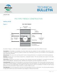
2.6 Preparation of Trench Bottom<br />
The trench bottom should be smooth and free from stones greater than<br />
1.5 inches diameter, large dirt clods and any frozen material. Excavation at<br />
bells (bell holes) should be provided so that the pipe is uniformly supported<br />
along its length.<br />
Figure 4<br />
Generally, loose material left by the excavator on the trench bottom will be adequate<br />
for bedding the pipe barrel so that it is fully supported. (See Figure 4.)<br />
Where the excavator cuts a very clean bottom, soft material can be shaved<br />
down from the sidewalls to provide needed bedding. If the trench bottom is<br />
rocky or hard, as in shale, place a 4-inch layer of selected backfill material to<br />
provide a cushion for the pipe. In rock excavation it is necessary that rock be<br />
removed and a bed of sand or selected backfill at least 4 inches deep be placed<br />
on the bottom of the trench to provide a cushion for the pipe. A pipeline of any<br />
material, which in the absence of a bedding cushion, resting directly on rock is<br />
subject to breakage under the weight of the backfill load, surface load or earth<br />
movements. When an unstable trench bottom is encountered and, in the opinion<br />
of the engineer, it cannot support the pipe, an additional depth should be excavated<br />
and refilled to the pipe grade with material approved by the engineer.<br />
Trenches can be dangerous and the contractor has the responsibility of ensuring<br />
that all safety regulations and design requirements have been observed<br />
for the protection of the workers and the public.<br />
18 IRRIGATION & I.P.S. PRESSURE INSTALLATION GUIDE
3.0 Pipeline Construction<br />
3.1 Inspection<br />
Pipe and accessories should be inspected for defects and cleanliness prior<br />
to lowering into the trench. Any defective, damaged or unsound material<br />
should be repaired or replaced and foreign matter or dirt should be removed<br />
from the interior of the pipe and accessories before lowering into<br />
the trench.<br />
3.2 Lowering Pipe and Accessories into Trench<br />
All pipe, fittings, valves and accessories should be carefully lowered into the<br />
trench using suitable equipment in such a manner as to prevent damage<br />
to pipe and accessories. PIPE AND ACCESSORIES SHOULD NEVER BE<br />
DROPPED OR DUMPED INTO THE TRENCH.<br />
Caution: Heavy impact may cause a slight longitudinal indentation in the<br />
outside of the pipe and a crack on the inside. This will result in a split as<br />
soon as the pipe is placed under pressure. Any pipe that has been impacted<br />
should be examined closely for this type of damage.<br />
3.3 Assembly of <strong>JM</strong> <strong>Eagle</strong> Ring-Tite PVC Pipe<br />
The Ring-Tite joint product is a push-on assembly in which the lubricated<br />
spigot end is inserted under the rubber Rieber ® gasket and into the bell as<br />
described in this installation guide. The Ring-Tite joint assembly provides for<br />
the completion of tight, dependable joints in minimum time when the following<br />
procedure is adhered to.<br />
NOTE: Other types of gaskets may be provided. <strong>JM</strong> <strong>Eagle</strong> is in the process<br />
of converting all gasketed products to the Rieber ® ring gasket.<br />
* Rieber ® is a registered trademark of TI Specialty Products Inc.<br />
IRRIGATION & I.P.S. PRESSURE INSTALLATION GUIDE<br />
19
3.4 Assembly Instructions<br />
<strong>JM</strong> <strong>Eagle</strong> supplies a standard Rieber ® gasket for water service with its pressure<br />
products and an oil resistant gasket under special request. The correct<br />
gasket for water service is not marked with any identifiers. The oil resistant<br />
gasket for special services has a blue band on the visible gasket face. Be<br />
sure you have the correct gasket for the installation. If you require oil resistant<br />
gaskets and those provided are for water service, then contact <strong>JM</strong> <strong>Eagle</strong> <br />
immediately. Do not use the water service gaskets or try to replace them.<br />
Note that either ring type may be used for conveying potable water. Field<br />
removal and replacement of Rieber ® gaskets is not recommended.<br />
1. Make certain that the gasket and bell are clean, with no dirt or foreign<br />
material that could interfere with proper seating of the gasket or assembly.<br />
If necessary, wipe the gasket and bell with a clean, dry cloth.<br />
Lubricating the Rieber ® gasket is not recommended.<br />
2. Make sure pipe end is clean. Wipe with a clean dry cloth around<br />
the entire circumference from the end to one inch beyond the reference<br />
mark. (See Figure 7.)<br />
Figure 7<br />
3. Lubricate the spigot end of the pipe, using only the <strong>JM</strong> <strong>Eagle</strong> approved<br />
lubricants (NSF approved) supplied.<br />
4. Be sure to cover the entire spigot end circumference, with particular attention<br />
paid to the beveled end of the spigot. The coating should be the<br />
equivalent of a brush coat of enamel paint. Lubricant can be applied to<br />
the pipe by hand, cloth, pad, sponge or glove. Lubrication of the gasket<br />
and/or ring groove may result in displacement during assembly.<br />
20 IRRIGATION & I.P.S. PRESSURE INSTALLATION GUIDE
Caution: After spigot end is lubricated, do not allow it to contact the bedding<br />
material. Small pieces of stone or soil may adhere to the lubricant and<br />
may become lodged between the spigot and the gasket upon assembly,<br />
resulting in a possible leak. (See Figure 8.)<br />
Figure 8<br />
NOTICE: The <strong>JM</strong> <strong>Eagle</strong> lubricant supplied with each shipment has been<br />
tested and approved for potable water service. Do not use non-approved lubricant,<br />
which may harbor bacteria or damage the gaskets or drinking water.<br />
5. Insert the beveled spigot end into the bell so that it is in contact with the<br />
Rieber ® gasket. Hold the pipe lengths being joined close to the ground<br />
(see Figure 9) and keep the lengths in proper alignment. Brace the bell,<br />
as shown, while the spigot end is inserted under the gasket, so that<br />
previously completed joints in the line will not be closed up or over-assembled.<br />
Push the spigot end in until the reference mark on the spigot<br />
end is flush with the end of the bell. Stabbing is not recommended and<br />
should be avoided to prevent damage to the gasket and joint.<br />
Figure 9<br />
IRRIGATION & I.P.S. PRESSURE INSTALLATION GUIDE<br />
21
Caution: If joint is over-assembled causing the spigot to jam into the neck<br />
of the bell, flexibility of the joint is lost. Uneven settlement of the trench or<br />
additional loading may cause this type of joint assembly to leak or crack.<br />
Do not assemble beyond the reference mark.<br />
Figure 10<br />
If undue resistance to insertion of the beveled end is encountered or the<br />
reference mark does not reach the flush position, disassemble the joint and<br />
check the position of the gasket. If it is twisted or pushed out of its seat, do<br />
not attempt to realign gasket, replace with another piece of pipe. Be sure<br />
both lengths are in proper alignment.<br />
NOTICE: Should a spigot or bell end become deformed under load at higher<br />
temperatures, it will be necessary to exercise more care in assembling the<br />
joint in order to prevent fish-mouthing of the gasket.<br />
6. No deflection at joint is allowed on 12 inches and smaller pipe. Pipe<br />
curvature should be accomplished by bending the pipe rather than<br />
deflecting the joints as noted in Section 2.2.<br />
NOTICE: If a pry-bar or backhoe is used for any assembly, a wood plank<br />
should be placed between the pipe and the machine to prevent damage. In<br />
addition, the force applied must be steady and constant. Do not ram or hit<br />
the pipe. For all pipe, a come-a-long jack is recommended over a backhoe.<br />
The method of attachment to the pipe must not abrade or damage the pipe<br />
in any way. Steps must be taken during installation using these methods to<br />
maintain correct alignment of the pipe. In addition, a helper should be present<br />
in all cases to assist the operator in knowing when the reference mark is<br />
reached properly.<br />
22 IRRIGATION & I.P.S. PRESSURE INSTALLATION GUIDE
3.5 Cutting<br />
A square cut is essential to ensure proper assembly and/or beveling. PVC<br />
pipe can easily be cut with a fine-toothed hacksaw, handsaw or a power-type<br />
saw with a steel blade or abrasive disc. (Do not use standard pipe cutters.<br />
The cutting wheel may crush or damage the pipe.) It is recommended that<br />
the pipe be marked around its entire circumference prior to cutting to ensure<br />
a square cut. Do not burn the pipe while cutting.<br />
Figure 11<br />
NOTICE: <strong>JM</strong> <strong>Eagle</strong> recommends using proper personal protective eqipment,<br />
such as gloves and safety glasses, when cutting PVC pipe.<br />
3.6 Beveling<br />
Use a factory-finished beveled end as a guide to determine the angle and<br />
length of taper. The end may be beveled using a plastic pipe-beveling tool<br />
as shown, which will cut the correct taper automatically or such tools as<br />
the Stanley “Surform” No. 399, a coarse file or rasp. A portable sander or<br />
abrasive disc may also be used to bevel the pipe end. Remove all burrs and<br />
raised edges prior to assembly to avoid cutting the gasket.<br />
3.7 Locating Reference Mark<br />
With a pencil, crayon or permanent marker, locate the reference mark at the<br />
proper distance from the beveled end. The reference mark may be located<br />
accurately by using a factory-marked end of the same pipe as a guide.<br />
IRRIGATION & I.P.S. PRESSURE INSTALLATION GUIDE<br />
23
3.8 Assembly at Fittings and Adaptors<br />
<strong>JM</strong> <strong>Eagle</strong> IPS <strong>Pressure</strong> and <strong>Irrigation</strong> Pipe are manufactured with an IPS<br />
and/or PIP outside diameter. This means that this pipe can be directly connected<br />
to IPS OD products (i.e., steel pipe accessories) and/or common<br />
irrigation equipment and valves.<br />
Additionally, other accessory items may be joined to <strong>JM</strong> <strong>Eagle</strong> IPS <strong>Pressure</strong><br />
and <strong>Irrigation</strong> Pipe through the use of specially designed transition gaskets<br />
or fittings.<br />
No extra support need be provided for these fittings and adaptors, but any<br />
heavy metal fittings or valves must be individually supported to avoid differential<br />
settlement between fittings and pipe. Note that fittings and valves<br />
in-line will require thrust blocking as specified in Section 3.9.<br />
Fittings and adaptors are usually installed at predetermined locations and<br />
therefore, a tie-in length of less than 20 feet will usually be required.<br />
1. Be sure the correct gasket is used with the bell or fitting.<br />
2. Bevel on the spigot should approximate the cast iron bevel, which is<br />
shorter and steeper. The reason for this is that the depth of the bell<br />
or fitting is shorter than the PVC bell. The reduced length of taper will<br />
allow a greater flat sealing surface and minimize the possibility of the<br />
gaskets, seating on the bevel, which may cause leakage.<br />
3. When connecting to a mechanical joint or flanged fitting, a beveled<br />
spigot is not recommended or required. Cut off beveled end of pipe<br />
prior to insertion into M-J style fitting.<br />
3.9 Thrust Blocking and Anchorage at Fittings<br />
Thrust backing (see Figure 12) is needed wherever the pipeline:<br />
1. Changes direction, as at tees, bends or crosses.<br />
2. Changes in size, as at reducers.<br />
3. Stops, as at dead ends.<br />
4. Valves, at which thrust develops when closed.<br />
24 IRRIGATION & I.P.S. PRESSURE INSTALLATION GUIDE
Figure 12<br />
3.9.1 Determining Size and Type of Thrust Blocking<br />
Size and type of blocking depends on pressure, pipe size, kind of soil and<br />
type of fitting. Common thrust block configurations are shown in Figure 13.<br />
At vertical bends, anchor pipelines to resist outward or horizontal thrusts as<br />
shown in Figure 14. If thrusts due to high pressure are expected, anchor the<br />
valves as shown in Figure 15. In all cases, thrust blocking and anchorages<br />
should be designed by a competent engineer to ensure adequate safety and<br />
support based on the actual field conditions encountered. Failure to design<br />
thrust blocking and anchorage adequately may result in damage to the pipe,<br />
property and/or people.<br />
Figure 14<br />
If the engineer has not specified the size of a thrust block, take the following<br />
steps to determine the bearing area required for a thrust block.<br />
IRRIGATION & I.P.S. PRESSURE INSTALLATION GUIDE<br />
25
Example: A 90-degree bend for an 18 inch–125 psi irrigation line that will<br />
be tested at 100 psi. Soil is sand.<br />
1. Refer to Table 4B and note that the thrust developed for each 100<br />
psi water pressure at an 18-inch 90-degree bend is 38,841 pouds for<br />
each 100 psi of water pressure.<br />
2. In Table 6, find that the bearing power of sand is 2,000 pounds per<br />
square foot. Dividing the total force of 38,841 lbs by 2,000 pounds per<br />
square foot, we have a total area of thrust backing required of 19.4<br />
square feet or an area of 4 feet 5 inches by 4 feet 5 inches.<br />
THRUST AT FITTINGS PRODUCED BY 100 PSI OF WATER<br />
PRESSURE IN <strong>JM</strong> EAGLE PVC PRESSURE RATED PIPE (psf)<br />
PIPE SIZE<br />
(inches)<br />
FITTING<br />
90 BEND 45 ELBOW TEE AND PLUGS<br />
1.5 415 225 295<br />
2 645 350 455<br />
2.5 935 510 660<br />
3 1,395 755 985<br />
4 2,295 1,245 1,620<br />
5 3,400 1,900 2,440<br />
6 4,950 2,680 3,500<br />
8 8,375 4,540 5,930<br />
10 12,795 6,895 9,075<br />
12 18,000 9,700 12,765<br />
Table 4A (IPS <strong>Pressure</strong> pipe)<br />
26 IRRIGATION & I.P.S. PRESSURE INSTALLATION GUIDE
THRUST AT FITTINGS PRODUCED BY 100 PSI OF<br />
WATER PRESSURE IN <strong>JM</strong> EAGLE PVC IRRIGATION PIPE (psf)<br />
PIPE SIZE<br />
(inches)<br />
FITTING<br />
90 BEND 45 ELBOW TEE AND PLUGS<br />
6 4,187 2,266 2,960<br />
8 7,396 4,003 5,230<br />
10 11,556 6,254 8,171<br />
12 16,640 9,006 11,767<br />
15 26,000 14,072 18,385<br />
18 38,841 21,021 27,465<br />
21 53,984 29,217 38,172<br />
24 68,324 36,979 48,313<br />
27 86,782 46,968 61,364<br />
Table 4B (<strong>Irrigation</strong> pipe)<br />
ALLOWABLE BEARING OF SOILS<br />
SOIL<br />
BEARING (psf)<br />
Muck, peat, etc. 0<br />
Soft Clay 1,000<br />
Sand 2,000<br />
Sand and Gravel 3,000<br />
Sand and Gravel cemented with Clay 4,000<br />
Hard Shale 10,000<br />
Table 5<br />
NOTICE: Allowance in total bearing area should be made for possible water<br />
hammer in the line.<br />
* <strong>JM</strong> <strong>Eagle</strong> assumes no responsibility for the above bearing load data,<br />
which was compiled from various sources. The engineer is responsible for<br />
determining safe bearing loads and when doubt exists, soil-bearing tests<br />
should be specified. The bearing loads given are for horizontal thrusts when<br />
depth of cover is 2 feet.<br />
IRRIGATION & I.P.S. PRESSURE INSTALLATION GUIDE<br />
27
In soft, unstable soils such as muck or peat, thrusts are resisted by running<br />
corrosion-resistant tie rods to solid foundations or by removing the soft material<br />
and replacing it with a ballast of sufficient size and weight to resist the<br />
thrusts developed.<br />
Pre-cast thrust blocks should not be placed directly against PVC pipe to<br />
avoid point loading and provide adequate force distribution.<br />
3.9.2 Upward Thrusts at Fittings<br />
Where a fitting is used to make a vertical bend, anchor the fitting to a thrust<br />
block braced against undisturbed soil. The thrust block should have enough<br />
resistance to withstand upward thrusts at the fitting. See Figure 14.<br />
Figure 14<br />
3.9.3 Anchorage of Pipe on Slopes<br />
Anchors on slopes are needed only when there is the possibility of backfill<br />
slipping downhill and carrying the pipe with it. Usually, well-drained soil,<br />
carefully tamped in 4-inch layers up to the top of the trench, will not slide and<br />
pipe anchors will not be required.<br />
Where soil slippage is a possibility, anchors keyed in undisturbed soil can be<br />
fastened to every other length of pipe.<br />
3.9.4 Anchorage of VALVES IN THE LINE<br />
Under pressure conditions, valves must be anchored as shown in Figure 15<br />
against the thrust created when the valve is closed. The area of undisturbed<br />
28 IRRIGATION & I.P.S. PRESSURE INSTALLATION GUIDE
soil, which braces the thrust block, must be large enough to withstand the<br />
thrust in whatever direction it is exerted.<br />
Figure 15<br />
3.9.5 Construction of Thrust Backing<br />
1. Concrete thrust blocks are constructed by pouring concrete between<br />
the fitting and the undisturbed bearing wall of the trench. A dry mixture<br />
is prepared so that the concrete may be easily shaped into the<br />
desired form, a wedge with the wide end against the solid wall. Note<br />
the shapes and positions of the thrust blocks in the drawings.<br />
2. Cinder blocks, wood, dry sand-cement mix or other materials may be<br />
used for pipe sizes less than 6 inches provided that (a) there is sufficient<br />
bearing area between backing and fitting, and (b) the backing<br />
has sufficient strength to withstand the thrust load. If wood is used, it<br />
must be treated to prevent deterioration.<br />
3. As an alternative, mechanical thrust restrainers may be used to resist<br />
the thrust developed.<br />
3.10 Thrust-Restraint Joints<br />
Various types of thrust-restraint joints are currently promoted for use with<br />
PVC pipe. These include couplings, which require grooving the pipe, and<br />
various fittings with set screws that bear on the pipe wall. These devices<br />
can be uniformly recommended by <strong>JM</strong> <strong>Eagle</strong> for use with its products.<br />
For installation follow the recommendation of the device manufacturer.<br />
IRRIGATION & I.P.S. PRESSURE INSTALLATION GUIDE<br />
29
3.11 Service Connections<br />
Service connections may be made to <strong>JM</strong> <strong>Eagle</strong> IPS <strong>Pressure</strong> and <strong>Irrigation</strong><br />
Pipe by means of a saddle or a sleeve and valve in the line at the service location.<br />
Due to the in-depth knowledge required to make proper taps safely,<br />
please refer to Uni-Bell Publication UNI-PUB-08-07, “Tapping <strong>Guide</strong> for PVC<br />
<strong>Pressure</strong> Pipe.”<br />
3.11.1 Saddles<br />
With saddle connections, a <strong>JM</strong> <strong>Eagle</strong> IPS <strong>Pressure</strong> and <strong>Irrigation</strong> Pipeline<br />
can be tapped before or after the line goes into service. Check with saddle<br />
manufacturers for recommended pressure rating of saddles used.<br />
Warning: Use of improper tapping procedures or tools may result in serious<br />
damage to pipe, property and/or people. Do not tap prior to obtaining<br />
the complete tapping guide.<br />
4.0 Pipe Embedment<br />
Below is an illustration (Figure 16) of a typical trench with all major regions<br />
identified as they will be addressed in the following sections.<br />
Pipe<br />
zone<br />
Springline<br />
of pipe<br />
6 inch-12 inch<br />
Initial<br />
backfill<br />
Haunching<br />
Bedding<br />
max. 6 inch<br />
Embedment<br />
Material<br />
Foundation<br />
(may not be required)<br />
Figure 16<br />
30 IRRIGATION & I.P.S. PRESSURE INSTALLATION GUIDE
4.1 Bedding<br />
Bedding is required primarily to bring the trench bottom up to grade. Bedding<br />
materials should be placed to provide uniform longitudinal support under<br />
the pipe to prevent low spots. Blocking should not be used to bring the<br />
pipe to grade. Bell holes at every joint will allow for the joint to be assembled<br />
properly and maintain uniform support. Under normal circumstances a bedding<br />
of 4 to 6 inches compacted is of sufficient thickness for the bedding. If<br />
the native trench soil is comprised of fine grain soils and migration of those<br />
soils into the bedding material is anticipated, either wide trench construction,<br />
a well-graded bedding material without voids or a fabric barrier should be<br />
used to avoid compromising the trench backfill materials.<br />
4.2 Backfilling and Tamping<br />
Backfilling should follow pipe assembly as closely as possible. This protects<br />
the pipe from falling rocks, eliminates possibility of lifting the pipe from<br />
grade due to flooding of an open trench, avoids shifting pipe out of line<br />
by cave-ins, and in cold weather lessens the possibility of backfill material<br />
becoming frozen.<br />
4.2.1 Haunching and Initial Backfill<br />
There are two basic purposes of the haunching and initial backfilling of a<br />
flexible conduit such as PVC pipe:<br />
1. To provide the soil side support, which is necessary to enable the pipe<br />
and the soil to work together to meet the designed load requirements<br />
within the allowable deflection limits.<br />
2. To provide protection for the pipe from impact damage due to large<br />
rocks, etc., contained in the final backfill.<br />
The essentials of satisfactory haunching and initial backfilling can be summarized<br />
as follows: Provide approved materials, properly compacted continuously<br />
above the bedding and around the pipe to the spring-line, as well<br />
as between the pipe and undisturbed trench walls.<br />
IRRIGATION & I.P.S. PRESSURE INSTALLATION GUIDE<br />
31
After the bedding material has been placed according to Section 4.1, place<br />
the haunching and initial backfill by hand to a 1-foot minimum depth of cover<br />
above the pipe to give pipe support and cushion. In doing so, proper control<br />
should be exercised to avoid vertical and horizontal displacement of the pipe<br />
from proper alignment. (See Figure 17.) This backfill should be a selected material,<br />
free from rocks greater than 1.5 inches in diameter, dirt clods or frozen<br />
material. This material is solely responsible for providing effective support of<br />
the pipe in the haunching area and limiting deflection. This is accomplished<br />
by tamping the embedment materials under the haunches and around the<br />
pipe to the spring-line of the pipe.<br />
A. Right—Backfill correctly placed by hand<br />
filling all voids.<br />
B. Wrong—Backfill not placed evenly.<br />
Figure 18<br />
Side support is accomplished by tamping the soil firmly under the haunches<br />
of the pipe out to the trench walls. Tamping should be done in layers no<br />
greater than 6 inches. If automatic tampers are used, care should be exercised<br />
to avoid damaging the pipe. For more information on tamping, see<br />
Section 4.4.1.<br />
The immediate placement of initial backfill will provide adequate weight of<br />
soil on the pipe so that expansion and contraction will be evenly distributed<br />
over each pipe length. This portion of the backfill begins at the spring-line<br />
of the pipe and extends to some predetermined distance above the pipe.<br />
Since little to no side support is derived from the soils placed in this area,<br />
native soils maybe used without tremendous compaction efforts, unless in<br />
the influence zone of other structures. It should be noted that at shallow<br />
32 IRRIGATION & I.P.S. PRESSURE INSTALLATION GUIDE
depths of cover (less than 3 feet) flexible conduits may deflect and rebound<br />
under dynamic loading if the trench width is not highly compacted, resulting<br />
in damage to road surfaces. For pipes buried under flexible road surfaces<br />
at depths less than 3 feet, it is recommended that a minimum of 90 percent<br />
Proctor density be achieved from the bottom of the trench up to the road surface<br />
using Class I or Class II materials as described in Appendix 1. Minimum<br />
cover is recommended to be 1-foot from the top of rigid road surfaces or the<br />
bottom of flexible road surfaces.<br />
NOTICE: For water pipe installations the top area of the bells can be left<br />
exposed for visual inspection during the test if required.<br />
4.3 Completing the Backfill<br />
Balance of backfill need not be as carefully selected as the initial material,<br />
unless specified by the engineer. Care should be taken, however, to avoid<br />
including large stones that could damage the pipe by dropping on it or by<br />
being forced down on to the pipe under the weight of the final backfill.<br />
4.3.1 Final Backfill<br />
The final backfill should be placed and spread in uniform layers in such a<br />
manner as to completely fill the trench with a uniformly dense backfill load on<br />
the pipe and avoid unfilled spaces in the backfill. Rolling equipment should<br />
not be used until a minimum of 18 inches of backfill material has been placed<br />
over the top of the pipe. If a hydro hammer is to be used to compact the<br />
backfill, a minimum of 3 feet of cover is required. Unless otherwise specified,<br />
trenches under pavements, sidewalks or roads shall be backfilled and compacted<br />
to 90 percent density, as determined by the American Association of<br />
Highway and Transportation Officials Method T99 for State Compaction and<br />
Density of Soils. Unless specified, other trenches may be backfilled without<br />
controlled compaction in the final backfill. Additional backfill material should<br />
be supplied, if needed, to completely backfill the trenches or to fill depressions<br />
caused by subsequent settlement. For description of backfill materials<br />
and their recommended usage, please refer to Appendix 1.<br />
IRRIGATION & I.P.S. PRESSURE INSTALLATION GUIDE<br />
33
4.4 Compaction Methods<br />
The first step in providing effective support for the pipe in the haunching<br />
area is to tamp the embedment materials under the haunches and around<br />
the pipe to the spring-line of the pipe. Tamping should be done with hand<br />
tamping bars, mechanical tampers, or by using water to consolidate the<br />
embedment materials. With hand tamping, satisfactory results can be accomplished<br />
in damp, loamy soils and sands. For more cohesive soils, the<br />
necessary compaction may require the use of mechanical tampers. Water<br />
tamping should be limited to trenches excavated in soils in which water<br />
drains through quickly and, in so doing, compacts the embedment material.<br />
4.4.1 Tamping Bars<br />
Two types of tamping bars should be available for a good tamping job. The<br />
first should be a bar with a narrow head. (See A or B of Figure 18.) These<br />
are used to tamp under the pipe. The second tamping bar should have a flat<br />
head. It is used to compact the soil along the sides of the pipe to the trench<br />
walls. (See Figure 18C.)<br />
1” bar<br />
¾” - 1“<br />
or 1¼” pipe<br />
6’<br />
weld to flat bar<br />
6” x 4” x 1<br />
30° bend<br />
30°<br />
bend<br />
tee and two<br />
4” nipples<br />
A B C<br />
Figure 19<br />
Do not attempt to use the flat tamper (C) in place of A or B.<br />
34 IRRIGATION & I.P.S. PRESSURE INSTALLATION GUIDE
4.4.2 Mechanical Tampers<br />
Care should be taken to avoid contact between the pipe and compaction<br />
equipment. Compaction of the embedment material should generally<br />
be done in such a way that the compaction equipment is not used directly<br />
above the pipe until sufficient backfill has been placed to ensure that the use<br />
of compaction equipment will not damage the pipe or cause deflection of<br />
the pipe.<br />
When hydro-hammers are used to achieve compaction, they should not be<br />
used within 3 feet of the top of the pipe and then, only if the embedment<br />
material density has been previously compacted to a minimum 85 percent<br />
Proctor density.<br />
4.4.3 Flood or Water Tamping<br />
Flooding or water tamping should be used only in trenches that are excavated<br />
in soils from which water drains quickly and, at the same time, compacts<br />
the haunching material.<br />
If flooding is used, the approved embedment material is first hand placed,<br />
making certain all voids under, around, and along both sides of the pipe and<br />
couplings are filled. Initial embedment material should be placed to a height<br />
sufficient to prevent floating of the pipe.<br />
4.4.4 Water-Jetting<br />
The introduction of water under pressure to the embedment material is not<br />
to be used to compact the embedment material of PVC pipe or any other<br />
flexible conduit.<br />
IRRIGATION & I.P.S. PRESSURE INSTALLATION GUIDE<br />
35
4.4.5 Sheeting and Trench Boxes<br />
When sheeting is used, it should be left in place unless it is designed to<br />
prevent disturbing the soil adjacent to the pipe when pulled and removed.<br />
If heavy wooden sheeting has to be pulled, well-graded granular material<br />
should be placed on each side of the pipe for a distance of at least two pipe<br />
diameters. The granular material should be compacted to at least 90 percent<br />
Standard Proctor density.<br />
Whenever possible, sheeting and bracing should be installed so that the<br />
bottom of the sheeting extends no lower than the spring-line of the pipe.<br />
When installed in this manner, pulling the sheeting will not disturb the embedment<br />
material providing sidewall support for the pipe. If a trench box is<br />
used, it should be designed so that the backend of the sides do not extend<br />
below the pipe spring-line. This will allow filling and compaction of the annular<br />
space as the trench box is moved forward.<br />
5.0 Pipe Testing and Repair<br />
5.1 Pipe Deflection<br />
Under ordinary circumstances, the deflection of PVC pressure pipe is of no<br />
concern because the internal pressure of the pipe is much greater than the<br />
external load placed on the pipe, thus no deflection occurs. However, in<br />
some cases these pipes are used for force mains or gravity flow applications.<br />
Towns and municipalities normally set the long-term deflection limits of PVC<br />
at 7.5 percent by ASTM D3034 (Appendix), to provide a very conservative<br />
factor of safety against structural failure. However, it should be noted that<br />
PVC sewer pipe will have a minimum safety factor of 4 in structural failure at<br />
this limit. To ascertain how a certain PVC product will deflect under various<br />
loading conditions, backfill types and depths, one may contact <strong>JM</strong> <strong>Eagle</strong> for<br />
design charts specific to a situation.<br />
36 IRRIGATION & I.P.S. PRESSURE INSTALLATION GUIDE
5.1.1 Deflection Testing<br />
It is the position of <strong>JM</strong> <strong>Eagle</strong> that deflection testing of PVC pipe is unnecessary<br />
when pipe is installed in accordance with the acceptable practices<br />
stated in this guide. Most towns and municipalities limit initial deflection to 5<br />
percent, when in actuality ASTM D3034 recommends PVC pipe deflection<br />
7.5 percent of base inside diameter. Thus, exceeding these limits does not<br />
necessarily indicate any structural damage, failure or reduction in life and<br />
only add to the cost of the project. Proof of this position is that more than<br />
750 million feet of PVC sewer pipe are performing satisfactorily in the field<br />
today. On the other hand, where improper installation practices are known or<br />
suspected, questionable bedding materials are employed, and/or installation<br />
conditions are severe, deflection testing of these sections of the installation<br />
should be considered advisable by the engineer. In the event that deflection<br />
measurement is a requirement, please consult <strong>JM</strong> <strong>Eagle</strong> Publication <strong>JM</strong>E-<br />
05B, “Gravity Sewer <strong>Installation</strong> <strong>Guide</strong>.”<br />
5.2 Testing Water Pipe<br />
It is good practice to pressure test portions of a line as it is installed—before<br />
the entire line is completed. Before testing, all parts of the line should be<br />
backfilled and braced sufficiently to prevent movement under pressure. (See<br />
Figure 19.)<br />
In setting up a section of line for test, a provision for air relief valves should<br />
be made.<br />
There are three parts of the line to consider when testing:<br />
1. The run of pipe, which must be backfilled sufficiently to prevent movement<br />
under test pressure.<br />
2. Thrust blocks at fittings, which should be permanent and constructed<br />
to withstand test pressure. If concrete thrust blocks are used, enough<br />
time to permit the cement to set must elapse before testing.<br />
3. Test ends, which should be capped and braced to withstand the appreciable<br />
thrusts that are developed under test pressure. Refer to<br />
Section 3.9 on “Thrust Blocking and Anchorage at Fittings.”<br />
IRRIGATION & I.P.S. PRESSURE INSTALLATION GUIDE<br />
37
Typical End Cap<br />
Figure 19<br />
The last full length laid should be firmly wedged and braced to prevent kicking<br />
out under pressure. (See Figure 20.) All exposed pipe must be wedged<br />
or backfilled, in order to hold it securely in line. Using a plumb bob over a<br />
reference point on the pipe will check creeping when pressure is built up.<br />
Figure 20<br />
5.2.1 Filling the Line<br />
The line can be slowly filled from any available low-pressure source. The<br />
water can be introduced from lines in service through valve connections, by<br />
temporary connections to hydrants, to taps made in the new line, or at the<br />
connection in the end cap. All such connections, however, should be made<br />
at the lowest point in the line, if possible, to help eliminate air entrapment.<br />
Where a portion of the line is to be tested and has not yet been tied to the<br />
final source, some other source of water must be found. Table 6 shows the<br />
approximate volume of water required for filling <strong>JM</strong> <strong>Eagle</strong> IPS <strong>Pressure</strong> and<br />
<strong>Irrigation</strong> Pipe.<br />
38 IRRIGATION & I.P.S. PRESSURE INSTALLATION GUIDE
Volume of Water Required in Gallons/Foot<br />
PIPE SIZE<br />
(inches)<br />
PIPE SDR<br />
41 32.5 26 21 17<br />
1.5 — 0.13 0.12 0.12 0.11<br />
2 — 0.20 0.19 0.19 0.18<br />
2.5 — 0.29 0.28 0.27 0.26<br />
3 0.45 0.44 0.42 0.40 0.38<br />
4 0.74 0.72 0.70 0.67 0.63<br />
5 1.14 1.10 1.06 1.02 0.97<br />
6 1.61 1.56 1.51 1.45 1.37<br />
8 2.73 2.65 2.56 2.45 2.33<br />
10 4.24 4.12 3.98 3.81 3.61<br />
12 5.96 5.80 5.60 5.36 5.08<br />
Table 6A (IPS <strong>Pressure</strong> pipe)<br />
Volume of Water Required in Gallons/Foot<br />
PIPE SIZE<br />
(inches)<br />
PIPE SDR<br />
64 51 41 35 32.5<br />
6 — 1.42 1.38 1.36 1.34<br />
8 — 2.50 2.44 2.40 2.38<br />
10 — 3.90 3.82 3.74 3.71<br />
12 — 5.61 5.50 5.40 5.34<br />
15 8.92 8.77 8.59 8.43 8.34<br />
18 13.34 13.10 12.83 12.60 12.47<br />
21 — 18.22 17.84 17.50 17.33<br />
24 — 23.05 22.57 — 21.94<br />
27 — 29.28 28.67 — 27.84<br />
Table 6B (<strong>Irrigation</strong> Pipe)<br />
IRRIGATION & I.P.S. PRESSURE INSTALLATION GUIDE<br />
39
5.2.2 Relieving Air from the Line<br />
ALL AIR SHOULD BE VENTED FROM ALL HIGH SPOTS IN THE PIPELINE<br />
BEFORE MAKING EITHER PRESSURE OR LEAKAGE TESTS. AUTOMATIC<br />
AIR RELEASE VALVES ARE RECOMMENDED. Compressed entrapped air<br />
causes difficulty in pumping to required pressure for strength tests. Furthermore,<br />
a pipeline may leak compressed air when it is actually watertight. If this<br />
occurs during a leakage test, it will cause erroneous results. Most importantly,<br />
when entrapped air is compressed, it poses a severe explosion hazard and<br />
may result in pipe failure and/or injury to property and/or persons. Don’t use<br />
PVC for compressed air systems.<br />
5.3 <strong>Pressure</strong>-Strength Tests<br />
The purpose of a pressure-strength test is to make certain that the line will<br />
withstand normal working pressure plus reasonable excesses that may occur.<br />
In a properly designed line, excess pressures will be kept to a minimum<br />
by the use of automatic relief valves, slow closing and opening valves, slow<br />
pump starting and other controls. A test pressure of 25 percent above the<br />
normal operating pressure should generally be sufficient, unless the specification<br />
calls for greater pressure. Do not build test pressures greater than<br />
those specified. This can happen if the pressure is read from a gauge located<br />
at a high point in the line. In such cases the actual pressure at low points will<br />
be greater and might cause damage to the line. In all cases, it is important<br />
that no pressure test, regardless of duration, exceed the marked pressure<br />
capacity of the pipe and/or accessories being tested. Doing so might cause<br />
damage to the line or shorten the expected life of the system. For more<br />
detailed instructions on how to perform installation and pressure testing,<br />
consult ASTM D2774, “Underground <strong>Installation</strong> of Thermoplastic <strong>Pressure</strong><br />
Piping” and/or ASTM F690, “Standard Practice for Underground <strong>Installation</strong><br />
of Thermoplastic <strong>Pressure</strong> Piping <strong>Irrigation</strong> Systems.”<br />
40 IRRIGATION & I.P.S. PRESSURE INSTALLATION GUIDE
5.4 Making Leakage Tests<br />
The purpose of a leakage test is to establish that the section of line to be<br />
tested—including all joints, fittings, and other appurtenances—will not leak<br />
or that the leakage established is within the limits of the applicable leakage<br />
allowance. Leakage, if any, is usually involved in joints at saddles, valves,<br />
transition fittings, adaptors and not usually in pipe joints. Normal operating<br />
pressure is usually applied for tests. This should be maintained as constant<br />
as possible throughout the testing period. Measurement of the amount of<br />
additional water pumped in during the test will provide a measurement of the<br />
amount of leakage, if any. In setting up a section of line for testing, air relief<br />
valves should be provided. Air trapped in the line during the test will affect<br />
test results and can cause damage to the pipeline and/or injury to workers.<br />
Generally, the engineer will establish the duration of the test, the allowable<br />
leakage, and indicate the appropriate methods and procedures for testing.<br />
If not, a two-hour test is recommended and the allowable leakage shall be<br />
determined by the following formula:<br />
L = (ND P) / 7400<br />
L is the allowable leakage, in gallons per hour; N is the number of joints in<br />
the length of pipeline tested; D is the nominal diameter of the pipe in inches;<br />
and P is the average test pressure during the test in pounds per square inch<br />
gauge (PSIG). Leakage values determined by the above formula are shown<br />
in Table 7.<br />
Consideration should be given to any valves isolating the test section. Many<br />
waterworks valves are not designed for leak-proof operation. Leakage<br />
through these valves can distort actual leakage figures.<br />
IRRIGATION & I.P.S. PRESSURE INSTALLATION GUIDE<br />
41
Leakage Allowance-Gals per 100 Joints per Hour<br />
PIPE SIZE<br />
(inches)<br />
Test <strong>Pressure</strong>, PSI<br />
50 100 150 200 225<br />
1.5 0.143 0.203 0.248 0.287 0.304<br />
2 0.191 0.270 0.331 0.382 0.405<br />
2.5 0.239 0.338 0.414 0.478 0.507<br />
3 0.287 0.405 0.497 0.573 0.608<br />
4 0.382 0.541 0.662 0.764 0.811<br />
5 0.478 0.676 0.828 0.956 1.014<br />
6 0.573 0.811 0.993 1.147 1.216<br />
8 0.764 1.081 1.324 1.529 1.622<br />
10 0.956 1.351 1.655 1.911 2.027<br />
12 1.147 1.622 1.986 2.293 2.432<br />
15 1.433 2.027 2.483 2.867 3.041<br />
18 1.720 2.432 2.979 3.440 3.649<br />
21 2.007 2.838 3.476 4.013 4.257<br />
24 2.293 3.243 3.972 4.587 4.865<br />
27 2.580 3.649 4.469 5.160 5.473<br />
Table 7 (IPS <strong>Pressure</strong> and <strong>Irrigation</strong> Pipe)<br />
The leakage allowances indicated are intended for municipal water pipe<br />
distribution networks, which include numerous valves and fittings.<br />
5.5 Making Repairs to Damaged Pipelines<br />
When pipe has been damaged and repair is required, all damaged material<br />
may be replaced in kind or the pipe may be repaired using a repair clamp or<br />
other methods authorized by the engineer.<br />
If a repair clamp is to be used, the full circle type with opposed bolt line flanges<br />
is recommended and should be installed in accordance with the manufacturer’s<br />
instructions. Gouges, which have a depth greater than 10 percent<br />
42 IRRIGATION & I.P.S. PRESSURE INSTALLATION GUIDE
of the wall thickness of the pipe, should be repaired. If the damaged area<br />
is localized, a repair clamp may be used. When the damaged area extends<br />
beyond a localized area, it is recommended that the damaged section of<br />
the pipe be cut out and replaced. In such cases, repair clamps or Dressertype<br />
couplings will be required to join the pipe ends. Other types of couplings<br />
may be available. Please consult <strong>JM</strong> <strong>Eagle</strong> for acceptability of these<br />
other products.<br />
NOTE: Trenches and/or casing should be constructed and used in accordance<br />
with all applicable state and federal standards to ensure safety.<br />
NOTICE TO ALL READERS OF THIS GUIDE: PVC pipe installation may<br />
be hazardous to pipe, property and/or persons if this guide and/or the recommendations<br />
of <strong>JM</strong> <strong>Eagle</strong> are not adhered to fully. <strong>JM</strong> <strong>Eagle</strong> has made<br />
every effort to expose all known dangers of misusing PVC pipe in this guide;<br />
however, <strong>JM</strong> <strong>Eagle</strong> cannot possibly know or anticipate all situations or outcomes.<br />
<strong>JM</strong> <strong>Eagle</strong> maintains the position that PVC pipe is the most reliable<br />
and safest piping material available. Thus, <strong>JM</strong> <strong>Eagle</strong> encourages all users<br />
of its products to exercise good judgment when installing our products and<br />
to consult <strong>JM</strong> <strong>Eagle</strong> for additional information when questions or concepts<br />
illustrated herein are not fully answered or understood. It is recommended<br />
that all users of its products (or people handling) attend training on pipe construction,<br />
installation and safety prior to working with our products to ensure<br />
safety, knowledge and understanding. Should you need further assistance,<br />
please contact <strong>JM</strong> <strong>Eagle</strong> Product Assurance at (800) 621-4404.<br />
IRRIGATION & I.P.S. PRESSURE INSTALLATION GUIDE<br />
43
Appendix 1<br />
Embedment Materials<br />
Materials suitable for foundation and embedment are classified in the following<br />
Table A1.1. They include a number of processed materials plus soil<br />
types defined according to the Unified Soil Classification System (USCS) in<br />
ASTM D2487, “Standard Method for Classification of Soils for Engineering<br />
Purposes.” Table A1.2 provides recommendations on the installation and<br />
use based on class of soil or aggregates and location within the trench. It is<br />
important to engineer all materials used in the pipe trench to work together<br />
and with the native material surrounding the trench.<br />
Class IA Materials: Class IA materials provide the maximum stability and<br />
pipe support for a given density because of the angular interlocking of the<br />
material particles. With minimum efforts, these materials can be installed at<br />
relatively high densities over a wide range of moisture contents. These materials<br />
also have excellent drainage characteristics that may aid in the control<br />
of water. These soils are often desirable as embedment in rock cuts where<br />
water is frequently encountered. On the other hand, when ground water flow<br />
is anticipated, consideration should be given to potential migration of fines<br />
from adjacent materials into the open graded Class IA materials.<br />
Class IB Materials: Class IB materials are produced by mixing Class IA<br />
and natural or processed sands to produce a particle-size distribution that<br />
minimizes migration from surrounding soils that may contain fines. They are<br />
more widely graded than Class IA and thus require more compaction effort<br />
to achieve the minimum density specified. When these materials are properly<br />
compacted, these soils exhibit high stiffness and strength, and depending<br />
on the amount of fines, may be relatively free draining.<br />
Class II Materials: When Class II materials are compacted, they provide<br />
a relatively high level of pipe support. In most respects, they all have the<br />
desirable characteristics of Class IB materials when widely graded. However,<br />
open-graded groups may allow for migration and the sizes should be<br />
checked for compatibility with the native trench materials. Typically, Class II<br />
materials consist of rounded particles and are less stable than the angular<br />
materials of Class IA and IB unless they are confined and compacted.<br />
44 IRRIGATION & I.P.S. PRESSURE INSTALLATION GUIDE
Class III Materials: These materials provide less support for a given density<br />
than Class I or Class II materials. High levels of compaction effort are<br />
required if moisture content is not controlled. These materials will provide<br />
reasonable support once proper compaction is achieved.<br />
Class IV-A Materials: Class IV-A materials must be carefully evaluated<br />
before use. The moisture content of the materials must be near optimum<br />
to minimize compaction effort and achieve the required density. Properly<br />
placed and compacted, these soils can provide reasonable levels of pipe<br />
support. However, these materials may not be suitable under high fills, surface<br />
applied dynamic loads, or under heavy vibratory compactors and tampers.<br />
These materials should be avoided if water conditions in the trench<br />
may cause instability and result in uncontrolled water content.<br />
IRRIGATION & I.P.S. PRESSURE INSTALLATION GUIDE<br />
45
Table A1.1<br />
Description of Material Classification as Defined in ASTM D2321<br />
Class Type<br />
Soil Symbol<br />
Group<br />
Description ASTM D2487<br />
1.5 in<br />
(40 mm)<br />
Percentage Passing<br />
Sieve Sizes<br />
No.4<br />
(4.75 mm)<br />
No.200<br />
(.075 mm)<br />
Atterberg<br />
Limits<br />
LL PL Uniformity<br />
Cu<br />
Coefficients<br />
Curvature<br />
Cc<br />
IA<br />
Manufactured<br />
Aggregates:<br />
open graded,<br />
clean<br />
None<br />
Angular, crushed stone or rock,<br />
crushed slag, cinders or shell: large<br />
void content, contain little or no fines<br />
100% < or = 10% < 5%<br />
Non<br />
Plastic<br />
IB<br />
Manufactured,<br />
Processed<br />
Aggregates:<br />
dense graded,<br />
clean<br />
None<br />
Angular, crushed stone (or other<br />
Class IA materials) and stone/sand<br />
mixtures with gradations selected to<br />
minimize migration of adjacent soils:<br />
contain little to no fines<br />
100% < or = 50% < 5%<br />
Non<br />
Plastic<br />
II<br />
Coarse-Grained<br />
Soils: clean<br />
GW<br />
Well graded gravels and gravel-sand<br />
mixtures: little to no fines<br />
100%<br />
< 50% of<br />
coarse<br />
fraction<br />
< 5%<br />
Non<br />
Plastic<br />
> 4 1 to 3<br />
GP<br />
Poorly graded gravels and gravelsand<br />
mixtures: little to no fines<br />
< 4 < 1 or > 3<br />
SW<br />
Well graded sands and gravelly<br />
sands: little to no fines<br />
< 50% of<br />
coarse<br />
fraction<br />
> 6 1 to 3<br />
SP<br />
Poorly graded sands and<br />
gravelly sands: little to no fines<br />
< 6 < 1 or > 3<br />
Coarse-Grained<br />
Soils: borderline<br />
clean to w/fines<br />
Sands and gravels which<br />
are bordeline between clean and<br />
with fines<br />
100% varies<br />
5% to<br />
12%<br />
Non<br />
Plastic<br />
Same as<br />
for GW, GP,<br />
SW, and SP<br />
Based on tables found in the Uni-Bell ® PVC Pipe Association, “Handbook of PVC Pipe Design and Construction”.<br />
46 IRRIGATION & I.P.S. PRESSURE INSTALLATION GUIDE
Table A1.1 continued<br />
Percentage Passing<br />
Sieve Sizes<br />
Atterberg Limits Coefficients<br />
Class Type<br />
Soil Symbol<br />
Group<br />
Description<br />
ASTM D2487<br />
1.5 in<br />
(40 mm)<br />
No.4<br />
(4.75 mm)<br />
No.200<br />
(.075 mm)<br />
LL PL<br />
Uniformity<br />
Cu<br />
Curvature<br />
Cc<br />
III<br />
Coarse-<br />
Grained Soils<br />
w/ Fines<br />
GM<br />
Silty gravels,<br />
gravel-sand-silt<br />
mixtures<br />
100%<br />
> 50% of<br />
coarse fraction<br />
> 12% to <<br />
50%<br />
< 4 or < ”A” Line<br />
GC<br />
Clayey gravels,<br />
gravel-sand-clay<br />
mixtures<br />
< 7 and > ”A” Line<br />
SM<br />
Silty sands,<br />
sand-silt mixtures<br />
> 50% of<br />
coarse fraction<br />
> 4 or < ”A” Line<br />
SC<br />
Clayey sands,<br />
sand-silt mixtures<br />
> 7 and > “A” Line<br />
IV-A<br />
Fine-Grained<br />
Soils:<br />
Inorganic<br />
ML<br />
Inorganic silts<br />
and very fine<br />
sands, rock flour,<br />
silty or clayey fine<br />
sands, silts with<br />
slight plasticity<br />
100% 100% > 50% < 50 < 4 or < “A” Line<br />
CL<br />
Inorganic clays<br />
of low to medium<br />
plasticity, gravely<br />
clays, sandy<br />
clays, silty clays,<br />
lean clays<br />
> 7 and > “A” Line<br />
Based on tables found in the Uni-Bell ® PVC Pipe Association, “Handbook of PVC Pipe Design and Construction”.<br />
IRRIGATION & I.P.S. PRESSURE INSTALLATION GUIDE<br />
47
Table A1.2<br />
Recommendations for <strong>Installation</strong> and Use of Soils and Aggregates for Foundation, Embedment, and Backfill<br />
Soil Class as Defined in Table A1.1<br />
Class IA Class IB Class II Class III Class IV-A<br />
General<br />
Recommendations<br />
and Restrictions<br />
Do not use where condtions<br />
may cause migration<br />
of fines from adjacent soil<br />
and loss of pipe support.<br />
Suitable for use as a drainage<br />
blanket and underdrain<br />
in rock cuts where adjacent<br />
material is suitably graded.<br />
Process materials<br />
as required to obtain<br />
gradation which will<br />
minimize migration<br />
of adjacent materials.<br />
Suitable for use<br />
as drainage blanket<br />
and underdrain.<br />
Where hydraulic<br />
gradient exists check<br />
gradation to minimize<br />
migration. “Clean”<br />
groups suitable for<br />
use as drainage blanket<br />
and underdrain.<br />
Do not use where water<br />
conditions in trench may<br />
cause instability<br />
Obtain geotechnical evaluation<br />
of processed material.<br />
May not be suitable under<br />
high earth fills, surface applied<br />
loads and under heavy<br />
vibratory compactors and<br />
tampers. Do not use where<br />
water conditions in trench<br />
may cause instability.<br />
Foundation<br />
Suitable as foundation<br />
and for replacing overexcavated<br />
and unstable<br />
trench bottom as restricted<br />
above. Install and compact<br />
in 6-inch maximum layers.<br />
Suitable as foundation<br />
and for replacing<br />
over-excavated<br />
and unstable trench<br />
bottom. Install and<br />
compact in 6-inch<br />
maximum layers.<br />
Suitable as foundation<br />
and for replacing<br />
over-excavated and<br />
unstable trench<br />
bottom as restricted<br />
above. Install and<br />
compact in 6-inch<br />
maximum layers.<br />
Suitable as foundation<br />
and for replacing overexcavated<br />
trench bottom<br />
as restricted above. Do<br />
not use in thicknesses<br />
greater than 12 inches total.<br />
Install and compact in<br />
6-inch maximum layers.<br />
Suitable only in undisturbed<br />
condition and where trench<br />
is dry. Remove all loose<br />
material and provide firm,<br />
uniform trench bottom before<br />
bedding is placed.<br />
Based on tables found in the Uni-Bell ® PVC Pipe Association, “Handbook of PVC Pipe Design and Construction”.<br />
48 IRRIGATION & I.P.S. PRESSURE INSTALLATION GUIDE
Table A1.2 continued<br />
Soil Class as Defined in Table A1.1<br />
Class IA Class IB Class II Class III Class IV-A<br />
Bedding<br />
Suitable as restricted<br />
above. Install in 6-inch<br />
maximum layers.<br />
Level final grade by<br />
hand. Minimum depth<br />
4 inches (6 inches in<br />
rock cuts).<br />
Install and compact<br />
in 6-inch maxImum<br />
layers. Level final<br />
grade by hand.<br />
Minimum depth 4<br />
inches (6 inches in<br />
rock cuts).<br />
Suitable as restricted<br />
above. Install and compact<br />
in 6 inch maximum layers.<br />
Level final grade by hand.<br />
Minimum depth 4 inches<br />
(6 inches in rock cuts).<br />
Suitable only in dry trench<br />
conditions. Install and<br />
compact in 6 inch maximum<br />
layers. Level final<br />
grade by hand. Minimum<br />
depth 4 inches (6 inches<br />
in rock cuts).<br />
Suitable only in dry trench<br />
conditions and when optimum<br />
placement and compaction control<br />
is maintained. Install and compact<br />
in 6 inch maximum layers. Level final<br />
grade by hand. Minimum depth<br />
4 inches (6 inches in rock cuts).<br />
Haunching<br />
Suitable as restricted<br />
above. Install in 6-inch<br />
maximum layers.<br />
Work in around pipe<br />
by hand to provide<br />
uniform support.<br />
Install and compact<br />
in 6-inch maximum<br />
layers. Work in<br />
around pipe by hand<br />
to provide uniform<br />
support.<br />
Suitable as restricted<br />
above. Install and<br />
compact in 6 inch<br />
maximum layers. Work in<br />
around pipe by hand to<br />
provide uniform support.<br />
Suitable as restricted<br />
above. Install and<br />
compact in 6 inch<br />
maximum layers. Work in<br />
around pipe by hand to<br />
provide uniform support.<br />
Suitable only in dry trench<br />
conditions and when optimum<br />
placement and compaction control<br />
is maintained. Install and compact<br />
in 6 inch maximum layers. Work<br />
in around pipe by hand to provide<br />
uniform support.<br />
Initial<br />
Backfill<br />
Suitable as restricted<br />
above. Install to a<br />
minimum of 6 inches<br />
above pipe crown.<br />
Install and compact<br />
to a minimum of 6<br />
inches above pipe<br />
crown.<br />
Suitable as restricted<br />
above. Install and compact<br />
to a minumum of 6 inches<br />
above pipe crown.<br />
Suitable as restricted<br />
above. Install and compact<br />
to a minumum of 6<br />
inches above pipe crown.<br />
Suitable as restricted above. Install<br />
and compact to a minumum of 6<br />
inches above pipe crown.<br />
Final<br />
Backfill<br />
Compact as required<br />
by the engineer.<br />
Compact as required<br />
by the engineer.<br />
Compact as required by<br />
the engineer.<br />
Compact as required by<br />
the engineer.<br />
Suitable as restricted above.<br />
Compact as required by the<br />
engineer.<br />
Based on tables found in the Uni-Bell ® PVC Pipe Association, “Handbook of PVC Pipe Design and Construction”.<br />
IRRIGATION & I.P.S. PRESSURE INSTALLATION GUIDE<br />
49
Notes:
Notes:
Notes:
evised January 2009<br />
JmE-06b<br />
© J-m manufacturing co., Inc.<br />
Global HeadQuarTers:<br />
Nine Peach Tree hill Road<br />
Livingston, NJ 07039<br />
T: 973.535.1633<br />
f: 973.533.4185<br />
54 Building IRRIGATION essentials & I.P.S. PRESSURE www.Jmeagle.com INSTALLATION GUIDE<br />
for a better tomorrow<br />
reGional oFFiCe:<br />
5200 west century blvd<br />
Los Angeles, cA 90045<br />
T: 800.621.4404<br />
f: 800.451.4170