
You also want an ePaper? Increase the reach of your titles
YUMPU automatically turns print PDFs into web optimized ePapers that Google loves.
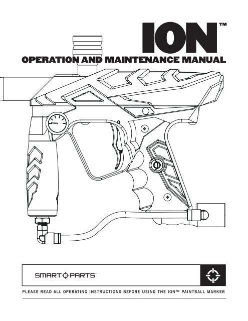
ION<br />
<br />
OPERATION AND MAINTENANCE MANUAL<br />
PLEASE READ ALL OPERATING INSTRUCTIONS BEFORE USING THE ION PAINTBALL MARKER
WARNING<br />
— USE ONLY A CO 2 TANK WITH AN ANTI-SIPHON TUBE.<br />
— Do not exceed 200psi inlet pressure to the <strong>Ion</strong>.<br />
— Do not replace any internal hose with any brand other than Smart Parts.<br />
— Do not use any type of hose clamp or overheat internal hoses—this can<br />
weaken and damage them.<br />
— Do not grease or oil the solenoid internals—this will cause it to jam.<br />
ION QUICK START<br />
1. Screw on the barrel, then place a barrel cover over the end of the barrel.<br />
2. Screw your air source into the <strong>Ion</strong>’s bottom line. If using Nitrogen/<br />
Compressed air, simply screw your tank in until it seals. If using CO2, be<br />
sure to only use a tank with an anti-siphon tube. Failure to use an antisiphon<br />
tube will cause a major decrease in performance and/or cause seal<br />
damage to your <strong>Ion</strong>. We also recommend using an on/off valve, as well.<br />
3. Place your hopper into the <strong>Ion</strong>’s feed tube. If the fit is a little tight, slowly<br />
spin the hopper clockwise until it fits all the way into the feed tube.<br />
Now add paintballs, then turn on your loader. Note: An electronic agitating<br />
hopper is recommended for use with the <strong>Ion</strong>.<br />
4. Making sure your goggles are on, remove the barrel cover. Turn the <strong>Ion</strong> on<br />
by depressing the membrane button for approximately two seconds. The<br />
on/off switch, which also functions as your safety, is located on the left<br />
side of the marker, just above the above the grip and behind the trigger<br />
guard. (Figure 1) The switch light will now blink rapidly red (green for UK<br />
users). The <strong>Ion</strong> is now on and in Vision mode.<br />
5. The <strong>Ion</strong> is now ready for play. Follow all safety regulations and rules<br />
before beginning and during play.<br />
NOTE 1: To degas the <strong>Ion</strong> properly and prevent damage to your bottle o-ring, turn the bottle<br />
out slowly as you cycle the marker after you have removed the hopper and paintballs. Make<br />
sure that there are no paintballs in the marker breach, turn the eyes off, and point the barrel<br />
towards the ground with a barrel cover on during removal.<br />
CAUTION: The <strong>Ion</strong>’s regulator will hold one to three shots worth of air after the air source<br />
has been removed. For safety, make sure to cycle your <strong>Ion</strong> with the air source completely<br />
removed UNTIL IT WILL NOT FIRE to be certain that all air is out of the <strong>Ion</strong> and regulator.<br />
NOTE 2: When not playing with and storing the <strong>Ion</strong> for an extended amount of time, disconnect<br />
and remove the battery to prevent draining it.
READ OWNER’S MANUAL BEFORE OPERATING<br />
THIS IS NOT A TOY. MISUSE MAY CAUSE SERIOUS INJURY OR DEATH. EYE<br />
PROTECTION DESIGNED SPECIFICALLY FOR PAINTBALL MUST BE WORN BY<br />
USER AND PERSONS WITHIN RANGE. RECOMMEND 18 YEARS OR OLDER<br />
TO PURCHASE. PERSONS UNDER 18 MUST HAVE ADULT SUPERVISION.<br />
POWER/MODE INDICATOR<br />
When you turn on the <strong>Ion</strong>, the red light inside the on/off switch (green for UK circuit boards) will<br />
begin blinking rapidly. This indicates your <strong>Ion</strong> is on, in Vision mode and ready to fire. This is the ideal<br />
mode for game play.<br />
If you tap the switch once more, the light will blink more slowly, in a double blink sequence.<br />
This means that the eyes are off, but the <strong>Ion</strong> will still fire. This is the desirable mode for degassing<br />
and testing.<br />
If the light blinks slowly, one blink at a time, the eyes are on, but you have an obstruction in the<br />
chamber. To remedy this, place the <strong>Ion</strong> into the eye off mode, clear the obstruction, then tap the<br />
on/off switch once more to place the <strong>Ion</strong> back into Vision.<br />
All other light indicators are covered in the CIRCUIT BOARD SETTINGS/ADJUSTMENT section.<br />
MAINTENANCE<br />
INCLUDED WITH YOUR ION<br />
TOOLS YOU WILL NEED<br />
.050" Allen Wrench 9/16" deep well socket and ratchet<br />
3/32" Allen Wrench Phillips screwdriver<br />
1/8" Allen Wrench<br />
Double Open End Wrench (5/8" & 7/16" ends)<br />
Spares parts kit<br />
STATISTICS<br />
Length/Weight:<br />
Operating Pressure:<br />
Propellant:<br />
Mode of Fire:<br />
Rate of Fire:<br />
Efficiency:<br />
Dwell Setting:<br />
Vision Eye:<br />
Power Source:<br />
Barrel Thread:<br />
Lubricant:<br />
18 inches (with stock 12" barrel), 2 lbs. 2 oz.<br />
180 psi<br />
CO 2 or Nitrogen/Compressed Air<br />
Full Auto, 3-shot burst, Semi automatic and Rebound<br />
17bps max (Semi & Rebound), 10bps (Auto & 3-shot burst—US board only)<br />
1200 shots (68ci, 4500psi tank), 800 shots (20oz. ANTI-SIPHON tank)<br />
52 (from bottom)<br />
Yes<br />
9 volt battery<br />
Impulse<br />
Use only “Shocker Grease”
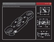
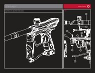
ION ASSEMBLY DIAGRAM
DISASSEMBLY<br />
1. Remove all paintballs and hopper, then remove all air sources to degas the <strong>Ion</strong>.<br />
2. Remove barrel. Looking from above the marker, remove the vertical screw with your 1/8" Allen<br />
wrench and set aside.<br />
3. Remove both left side grip screws (the side of the marker with the gauge on it), then open the<br />
grip and disconnect the battery. NOTE: ONLY REMOVE THE BATTERY BY SEPARATING THE<br />
CONNECTOR DIRECTLY FROM THE BATTERY. PULLING ON CIRCUIT BOARD WIRES CAN AND<br />
WILL CAUSE SIGNIFICANT AND EXPENSIVE DAMAGE.<br />
4. Remove the front and rear grip frame screws and set aside. Grasp the <strong>Ion</strong> body with one hand,<br />
the grip frame with the other. GENTLY AND SLOWLY roll the body from the grip frame until the<br />
you can access the top of the grip frame with an Allen wrench. (see figure 1)<br />
FIG. 1<br />
FIG. 2<br />
5. Using a 1/8" Allen wrench, remove the pneumatic banjo fitting from above the vertical adaptor.<br />
(see figure 2)<br />
6. Once again, GENTLY AND SLOWLY finish separating the the body from the grip frame then set<br />
grip frame aside. Turn the body upside down, then remove the Vision wire harness from the body.<br />
Next, remove the remaining two banjo fittings with your 1/8" Allen Wrench.<br />
7. While still keeping the body upside down, slide the metal sleeve out of the composite outer shell.<br />
Remove the Vision eye board by lifting straight up with your index finger and thumb. The Vision<br />
eye board is roughly c-shaped, with one eye on either point of the “C”. (see figure 3)<br />
FIG. 3<br />
8. Disassemble the front and rear metal body sections from each other by simply unscrewing them<br />
from each other. All that now remains are the bolt and bolt stop, both located in the rear half of<br />
the body assembly. Begin pulling out the bolt, then shift the bolt to the side to catch the end<br />
under the edge of the bolt stop. Pull until both the bolt and bolt stop are removed.
CLEANING/REASSEMBLY<br />
1. Cleaning the <strong>Ion</strong> is a simple process. Use a soft damp cloth to wipe down the parts, both internal<br />
and external. Wipe off old grease, dirt, debris, and broken paint. Pay special attention to the<br />
Vision eye board. Make sure the eyes are very clean and are not bent or damaged.<br />
2. To properly lubricate the <strong>Ion</strong>, grease the rearmost two o-rings located on the <strong>Ion</strong>’s bolt. Use a liberal<br />
amount, but do not over grease or “glob” it on. Also grease both o-rings on the bolt stop.<br />
3. Place the bolt stop into the rear body half; making sure that the concave side faces the back of<br />
the marker. Push the bolt stop in evenly, until it stops. Insert the bolt into the bolt stop/rear body.<br />
Screw the front half of the body into the rear half. Set the Vision eye board into its slot with the<br />
wire receptacle facing the rear of the body. Make sure the Vision eye board is seated all the way<br />
into the body.<br />
4. Inspect and thoroughly clean the area on the inner body where the Vision Eye sits with a cotton<br />
swab. Slide the metal body into the composite outer shell, making sure that the foil sticker inside<br />
the composite body is intact and clean. This sticker helps the eye in recognizing paintballs—DO<br />
NOT REMOVE.<br />
5. Replace the rear banjo fitting with the shortest hose into the body first. Be sure to set the<br />
solenoid head into the groove to align the circuit board and other hoses properly.<br />
6. Install the next longest hose and banjo into front fitting until snug. Replace the Vision eye<br />
harness into its receptacle. The Vision eye wire harness is meant to go in only one way. Look carefully<br />
at the plug on the wiring and the socket on the eye board. The prongs in the socket are set<br />
to one side, not centered, as are the channels in the plug. Be certain to line up the plug and<br />
socket properly when installing. Improper installation will cause damage to the socket, causing<br />
failure of the Vision eye. (see figure 4)<br />
FIG. 4<br />
7. Carefully feed the battery wires into the grip frame until the circuit board reaches the top of the<br />
grip frame. Feed the circuit board into the board channel in the grip frame.<br />
8. When the board is almost all the way in the grip frame, push the longest hose and banjo into its<br />
channel in the grip frame. Install the banjo fitting in the grip frame and tighten. Make sure all<br />
hoses and wires are inside the grip frame to prevent pinching or cutting of the wires. Gently push<br />
the circuit board down the channel, making sure to not bind or pinch the battery wires. Position<br />
the body onto the grip frame.<br />
9. Install vertical screw in front of barrel threads, then install both grip frame screws and tighten,<br />
all with your 1/8" Allen wrench. Attach battery and wrap wire around the top of the battery. Set<br />
into grip frame and reinstall grip screws.
SOLENOID DISASSEMBLY/MAINTENANCE<br />
1. For solenoid disassembly, use your 3/32" Allen wrench to pry the bracket from the back of the<br />
solenoid. BE SURE TO PLACE THE WRENCH BETWEEN THE BRACKET AND THE UPPER<br />
BLACK SECTION OF THE SOLENOID COIL. DO NOT PRY THE BRACKET AWAY ANYWHERE<br />
NEAR THE RED WIRED SECTION. This will cause solenoid damage. After the bracket has been<br />
removed, pull the solenoid head straight up. Now tip the solenoid body over to remove the<br />
armature. The armature comes out with extreme ease, so be careful to not lose it.<br />
2. Clean the inside of the solenoid with a cotton swab, making sure to remove all grease and debris.<br />
Wipe off the armature as well. Reassemble the solenoid by replacing the armature into the<br />
solenoid body, making sure that the end with the large rubber bumper goes in first. Replace the<br />
solenoid head by simply pushing it in to the solenoid body. Make sure that the long hoses and<br />
Vision eye strip are running over the trigger switch for proper orientation. Replace the bracket by<br />
pushing it onto the solenoid above and below the red wired section. Make certain that the bent<br />
section of the bracket goes onto the bottom side of the solenoid.<br />
NOTE: SHOULD YOU EVER NEED TO REMOVE THE HOSES FROM THE SOLENOID BARB<br />
FITTINGS, IT IS RECOMMENDED THAT YOU REMOVE THE SOLENOID HEAD FROM THE<br />
SOLENOID/CIRCUIT BOARD, THEN REMOVE THE HOSES BY HOLDING THE BARB FITTING<br />
WITH A BOX END OR SMALL CRESCENT WRENCH ON THE WRENCH FLATS FIRMLY WHILE<br />
STEADILY PULLING THE HOSE FREE. THIS PREVENTS STRESS ON THE SOLENOID<br />
COMPONENTS, AS WELL AS THE CIRCUIT BOARD. DO THE SAME WHEN INSTALLING NEW<br />
HOSES. ALSO APPLY A VERY SMALL AMOUNT OF LUBE TO THE FLARED BARB AREA OF THE<br />
FITTING TO EASE HOSE INSTALLATION.<br />
SOLENOID DIAGRAM
VELOCITY ADJUSTMENT<br />
To adjust <strong>Ion</strong> velocity up or down, use the 5/8"<br />
side of the provided wrench to turn the hex<br />
section located at the bottom of the regulator—<br />
clockwise to turn velocity up, counter-clockwise<br />
to turn velocity down. (see figure 5) Make<br />
only small adjustments at a time, shooting 5 to<br />
10 shots between adjustments to allow the<br />
regulator to achieve the new pressure. Always<br />
chronograph your <strong>Ion</strong> between adjustments.<br />
NOTE: NEVER ALLOW YOUR ION TO EXCEED<br />
300FPS AT ANY TIME.<br />
FIG. 5<br />
REGULATOR DIAGRAM
REGULATOR DISASSEMBLY/MAINTENANCE<br />
NOTE: ALL THREADS IN THE ION REGULATOR ARE REVERSE THREADED. THIS MEANS THAT<br />
TURNING THE INTERNAL PARTS CLOCKWISE LOOSENS, RATHER THAN TIGHTENS, THE PARTS.<br />
TURNING PARTS COUNTER-CLOCKWISE TIGHTENS THE PARTS.<br />
1. Make sure the <strong>Ion</strong> is completely degassed.<br />
2. Remove the regulator from the <strong>Ion</strong> by unthreading it counter-clockwise from the marker assembly.<br />
The vertical disc filter will come free as well when you do this. Check the filter for<br />
damage or debris, then set aside.<br />
3. Remove the rubber outer grip sleeve by pushing from the bottom up. Set aside.<br />
4. Using the provided 3/32" Allen Wrench, remove both set screws on the regulator body. One screw<br />
is located on the outside of the regulator body, about halfway up. The other is located inside an<br />
oval shaped hole near the bottom of the body. To remove this screw, you may have to turn the<br />
velocity adjuster with the provided 5/8" wrench to get the screw lined up in the oval slot.<br />
5. Using the 5/8" end of the provided wrench, completely remove the velocity adjuster by turning<br />
the adjuster clockwise until free from the regulator body. Set aside.<br />
6. Using a 9/16" deep well socket, turn the internal brass hex socket clockwise (right) until it comes<br />
free. As the brass hex piece comes free, so will the regulator spring.<br />
7. Using the provided 1/8" Allen Wrench, push the piston/regulator seat from the top of the<br />
regulator body out through the bottom until free.<br />
Thoroughly clean all the regulator parts by simply wiping clean with a paper towel or soft cloth.<br />
Lubricate both o-rings on the piston assembly. DO NOT LUBRICATE THE REGULATOR SEAT located<br />
at the end of the piston section OR the large o-ring located around the velocity adjuster.<br />
REGULATOR REASSEMBLY<br />
1. Push the piston/regulator seat, large end first, into the regulator body until it stops.<br />
2. Slip the regulator spring over the end of the piston inside the regulator body.<br />
3. Reinsert the brass hex piece and secure by turning the 9/16" deep well socket counter-clockwise<br />
until snug. If you have installed the correctly, brass will be visible through the set screw hole in<br />
the regulator body.<br />
4. Replace the velocity adjuster by threading in counter-clockwise the lower set screw hole appears<br />
in the oval slot on the regulator body.<br />
5. Replace both set screws into the regulator body until snug. Use a very small amount of blue<br />
(#242) Loctite or clear nail polish on the set screw threads in the velocity adjuster (inside the<br />
oval slot) during reassembly. DO NOT OVER TIGHTEN. Now slowly turn the adjuster all the way<br />
in counter-clockwise (left) until it stops. This will ensure that that the regulator is supplying no<br />
pressure into the marker.<br />
6. Slip rubber outer grip over the top of the regulator body until it stops.<br />
7. Gas up the <strong>Ion</strong> then turn the pressure up by using the included 5/8" wrench and slowly turning<br />
the velocity adjuster up (clockwise) until you reach 180psi. Be sure to cycle the <strong>Ion</strong> five to ten<br />
shots between adjustments.
CIRCUIT BOARD SETTINGS/ADJUSTMENT<br />
The <strong>Ion</strong> is programmed through the on/off switch and a similar switch located AT THE BOTTOM<br />
of the circuit board. (see figure 6) This switch is rectangular, flat, gray, and sits directly behind the<br />
trigger switch.<br />
To enter the programming mode and cycle through each programming setting:<br />
Turn the <strong>Ion</strong> on, then press the gray circuit board button once. The LED light will turn solid yellow.<br />
You are now at setting 1.<br />
To cycle through settings 2-6:<br />
Continue pressing the gray circuit board button. The LED lights will alternate between yellow and red,<br />
with alternating blinking patterns. The chart (below) explains the various modes and what they control.<br />
Changing circuit board settings:<br />
A) To alter any setting, use the gray circuit FIG. 6<br />
board button to select the setting.<br />
B) To make changes to a particular setting,<br />
press the on/off button. (Both LEDs will<br />
blink as adjustments are made.)<br />
C) When only the red LED is flashing, you have<br />
reached the end of the adjustment range.<br />
D) The UK board (green on/off light) is not<br />
capable of full auto or 3-shot burst modes.<br />
CIRCUIT BOARD SETTINGS<br />
Setting Light Indication Mode Function<br />
ONE<br />
Dwell Up (solid yellow)<br />
TWO<br />
Dwell Down (solid red)<br />
THREE<br />
Rate of Fire Down (single blink yellow)<br />
FOUR<br />
Rate of Fire Up (single blink red)<br />
FIVE<br />
Cycle Modes Up (double blink yellow)<br />
SIX<br />
Cycle Modes Down (double blink red)<br />
CYCLE MODES (from bottom)<br />
0. Semi<br />
1. Rebound<br />
2. 3-shot burst<br />
3. Full auto<br />
NOTE: UK markers (green on/off) do not have full auto or 3-shot modes.
TRIGGER ADJUSTMENT<br />
CAUTION: EXTREME TRIGGER ADJUSTMENTS (IN EITHER SCREW) CAN CAUSE THE ION TO NOT<br />
FIRE AND/OR DAMAGE THE TRIGGER SWITCH. MAKE CHANGES GRADUALLY AND MODERATELY.<br />
The <strong>Ion</strong> is equipped with an adjustable trigger. The length of the trigger stroke, tension and the<br />
trigger stop point can all be adjusted through two set screws.<br />
1. Located near the bottom of the trigger, this screw is adjusted with the provided .050" Allen<br />
wrench. Turning the screw in stops the trigger sooner after the trigger fires the <strong>Ion</strong>. Turning it out<br />
stops it later in the trigger cycle, making the trigger “sloppier”. (see figure 7)<br />
2. The other adjustment is the magnetic tension/pre-travel screw. It is located behind the trigger<br />
guard, just above the rubber grip. This screw shortens or lengthens the distance the trigger travels<br />
before the trigger switch is activated, as well as the magnetic tension of the trigger. The<br />
easiest way to adjust this screw is to remove the left sidegrip screws (side with gauge) and fold<br />
the grip behind the trigger guard. Turning the screw in brings the trigger closer to the trigger<br />
switch, shortening the trigger pull and making it “snappier”. (see figure 8)<br />
FIG. 7 FIG. 8
TROUBLESHOOTING<br />
THE ION IS LEAKING.<br />
A) INTERNALLY:<br />
— The pneumatic hoses are loose, damaged or not fully connected.Replace hoses with Smart Parts<br />
<strong>Ion</strong> hoses only.<br />
— One or more of the pneumatic banjo fittings is loose or damaged. Tighten banjo fitting(s) or<br />
replace with Smart Parts <strong>Ion</strong> banjo fittings only.<br />
— The solenoid armature is damaged or over pressurized. Replace armature and/or turn down operating<br />
pressure to less than 200psi.<br />
— The <strong>Ion</strong> is leaking down the barrel. One or more of the bolt o-rings and/or the bolt stop o-rings<br />
are damaged. Replace immediately.<br />
B) EXTERNALLY:<br />
— The macro line air fittings are venting or leaking air. Degas the <strong>Ion</strong>, push the macro line hose all<br />
the way into the fitting, then pull the hose back in the fitting, being certain that it catches and<br />
seals. If this does not work, replace the macro line hose with a new piece.<br />
— Air is leaking from in and/or around the regulator. The bottle o-ring at the regulator top is<br />
damaged. Replace it.<br />
— The regulator seat is contaminated and/or damaged. Replace with Smart Parts regulator seat only.<br />
(The regulator seat can be turned over and reused once.)<br />
THE ION IS INCONSISTENT OR SHOOTS DOWN.<br />
— The barrel bore size is wrong for your paint. Adjust bore size or choose better quality paintballs.<br />
— The <strong>Ion</strong>’s air source is low. Fill up your tank and make sure your tank is all the way on.<br />
— The <strong>Ion</strong>’s battery is low. Replace with a high quality 9 volt battery.<br />
— The regulator seat is contaminated or damaged. Replace with Smart Parts regulator seat only.<br />
— The SFT o-ring, located inside the metal inner body, in front of the ball detents, is damaged,<br />
swollen, or missing. Replace with Smart Parts 17/90 o-ring only.<br />
— Liquid CO 2 is entering the regulator. Install an anti-siphon tube or use compressed air.<br />
THE ION TURNS ON, BUT WILL NOT FIRE.<br />
— The battery is low or dead. Replace immediately.<br />
— The solenoid is clogged. Disassemble solenoid, clean armature and inside the solenoid body, then<br />
reassemble WITHOUT lubrication.<br />
— One or more of the trigger set screws are adjusted too far in, putting pressure on the trigger<br />
switch. Back screws out until trigger will activate the marker.<br />
— The trigger switch is damaged. Call Smart Parts or your local pro-shop for circuit board repair or<br />
replacement.<br />
— Regulator pressure is too high (above 300 psi). Lower pressure and/or replace regulator seat.<br />
— Liquid CO 2 is entering the regulator. Install an anti-siphon tube or use compressed air.<br />
THE ION BREAKS PAINT.<br />
— The <strong>Ion</strong>’s battery is low. Replace with a high quality 9 volt battery.<br />
— The ball detents are worn. Replace with <strong>Ion</strong> ball detents only.<br />
— The barrel bore size is wrong for your paint. Adjust bore size or choose better quality paintballs.<br />
— The dwell of the <strong>Ion</strong> is too high. Lower in 3 click increments. Retest in between adjustments.<br />
— The eyes are off. Place <strong>Ion</strong> into Vision mode.<br />
— The eyes are covered with paint, allowing the <strong>Ion</strong> to shoot without paintballs, even in Vision mode.<br />
Clean Vision eyes, as well as the slot they sit in, then reinstall.<br />
— The eyes are damaged or covered with paint or debris. Clean or replace the eye board.<br />
— The eye board wiring harness is damaged from improper installation. Replace.<br />
— Liquid CO2 is entering the regulator. Install an anti-siphon tube or use compressed air.
WARNING: LIQUID CO 2 COULD DAMAGE YOUR ION<br />
THE BIGGEST ENEMY OF THE ION, AND ANY PAINTBALL MARKER, IS LIQUID CO 2 .<br />
Gas state CO 2 is the preferred type of CO 2 used to power paintball markers. Liquid CO 2 is the more<br />
dense and liquefied version of the gas CO 2 used to power markers. Liquid CO 2 can, and will damage<br />
seals in the <strong>Ion</strong> as well as a massive chilling in certain temperatures, causing failure of the marker.<br />
Liquid CO 2 is found, at least a little, in every filled CO 2 tank. The cooler and more humid it gets, as<br />
well as how fast you shoot continuously, the more liquid CO 2 will form from the gas CO 2 in your tank,<br />
causing shoot down, freezing, massive velocity spikes, and seal damage.<br />
In the <strong>Ion</strong>, the biggest thing to look for is liquid CO 2 creeping into the regulator, causing it to rise<br />
above 200psi. The safest thing to do is to shut the air off and allow the <strong>Ion</strong> to warm up. This should<br />
be easy with any on/off valve, simply shut the valve off, and, if possible shoot out the excess pressure.<br />
DO NOT REMOVE THE TANK FROM THE MARKER UNLESS ABSOLUTELY<br />
NECESSARY IN THIS SITUATION. If liquid CO 2 is a persistent problem, you should have an<br />
anti-siphon tube, as well as an on/off valve, installed by Smart Parts or your local dealer. If you are<br />
uncertain as to what you should do, ask a qualified person as soon as possible.<br />
DO NOT ATTEMPT TO WORK ON A PRESSURIZED MARKER IF YOU DO NOT KNOW WHAT YOU<br />
ARE DOING.<br />
WARRANTY<br />
Smart Parts warrants for one (1) year to initial retail purchaser that the paintball marker and regulator are free from defects in materials<br />
and workmanship. Disposable parts (batteries, o-rings, seals, etc.) are not warranted. The valve assembly is warranted for six (6) months. The<br />
solenoid and electronics on the marker are warranted for six (6) months, plus an additional warranty of six months for electronic parts only (installation<br />
and labor are not included.) This warranty does not cover surface damages (scratches and nicks), misuse, improper disassembly and<br />
re-assembly, attempts made to drill holes or remove metal from the external surfaces which could degrade performance and reduce pressure<br />
safety factors of the marker. Do not make changes to the basic marker parts without written approval. The only authorized lubricant for the marker<br />
is DOW 33 Lubricant. Use of any other lubricant could result in voiding your warranty. <strong>Paintball</strong> markers are non-refundable. This warranty is<br />
limited to repair or replacement of defective parts with the customer to pay shipping costs. This warranty is effective only if the customer returns<br />
the warranty registration card enclosed with the marker. The warranty is non-transferrable. Do not attempt to alter the trigger assembly in any<br />
way, as this will void your Smart Parts Inc. warranty. Trigger alteration of any kind may result in serious injury.<br />
TECH SUPPORT<br />
Smart Parts, Inc.<br />
100 Station Street<br />
Loyalhanna, PA 15661<br />
Hours (EST)<br />
M-F 10-6<br />
800-992-2147<br />
smartparts.com<br />
West Coast Repair Center<br />
27326 Jefferson Ave #12<br />
Temecula, CA 92590<br />
Hours (PST)<br />
7 Days 11-6<br />
800-992-2147<br />
smartparts.com<br />
European Repair Center<br />
Unit 3 Old Bexley Business Park<br />
19 Bourne Road, Bexley, Kent<br />
DA5 1LR England<br />
Hours<br />
M-F 9-6, Saturday 10-4<br />
++44 (0)1322 555968<br />
smartpartseurope.co.uk
ION PARTS LIST: A
ION PARTS LIST: B
P. O. BOX 3200 | LATROBE, PA 15650 | 800.992.2147 | SMARTPARTS.COM