
You also want an ePaper? Increase the reach of your titles
YUMPU automatically turns print PDFs into web optimized ePapers that Google loves.
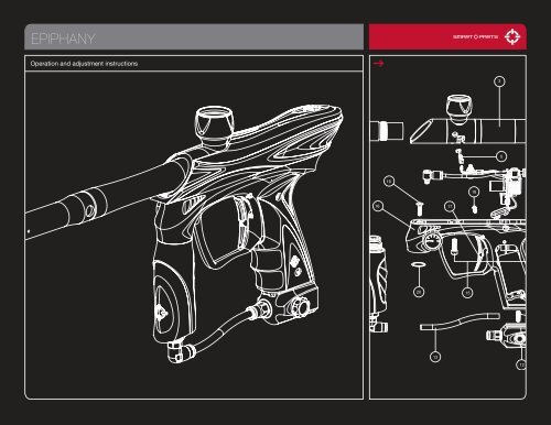
TABLE OF CONTENTSQuick StartGetting FamiliarBarrel Blocker/HopperGasesGas System MountingPaint/VelocityVision/DegassingElectronic AdjustmentDwellROF Delay/Fire ModesTrigger [ DISASSEMBLY/REASSEMBLY ]<strong>EPIPHANY</strong> PartsDisassemblyReassemblyEpiphany Volume InsertsSolenoidRegulatorBall DetentsTroubleshootingWarranty/Tech SupportCPS Table00020304-0506070809101112131415-161718192021-24While every effort has been made to ensure that the information contained in this guide is accurate and complete, no liability can be accepted for errorsor omissions. Smart Parts, Inc. reserves the right to change the specifications of the Epiphany at any time without prior notice. The latest versionof this manual may be downloaded free of charge at www.SmartParts.com.2425– THE <strong>EPIPHANY</strong> IS NOT A TOY– MISUSE OF THE <strong>EPIPHANY</strong> MAY RESULT IN SERIOUSINJURY OR DEATH.– EYE PROTECTION SPECIFICALLY DESIGNED FOR PAINT-BALL USE MUST BE IN COMPLIANCE WITH ASTM SPECI-FICATION F1776 AND MUST BE USED BY THE USER ANDANYONE WITHIN RANGE OF THE <strong>EPIPHANY</strong>– SMART PARTS RECOMMENDS THAT THE <strong>EPIPHANY</strong> ONLYBE SOLD TO PERSONS 18 AND OLDER.– THOROUGHLY READ THE <strong>EPIPHANY</strong> OPERATION ANDINSTRUCTION MANUAL BEFORE OPERATING.– TREAT EVERY PAINTBALL MARKER AS IF IT WERELOADED.– NEVER LOOK DOWN THE BARREL OF A PAINTBALLMARKER.– KEEP YOUR FINGER OFF THE TRIGGER UNTIL READY TOSHOOT.– NEVER POINT THE <strong>EPIPHANY</strong> AT ANYTHING YOU DON’TWISH TO SHOOT.– KEEP THE <strong>EPIPHANY</strong> ON SAFE (POWER OFF) UNTILREADY TO SHOOT. (SEE QUICK START)– KEEP THE BARREL BLOCKING DEVICE ON THE<strong>EPIPHANY</strong>’S MUZZLE WHEN NOT SHOOTING.(SEE BARREL BLOCKER SECTION).– ALWAYS REMOVE PAINTBALLS AND DEGAS THE<strong>EPIPHANY</strong> BEFORE DISASSEMBLY. (SEE DEGAS-SING SECTION.)– STORE AND TRANSPORT THE <strong>EPIPHANY</strong> UN-LOADED AND DEGASSED IN A SECURE PLACE.– FOLLOW ALL MANUFACTURER’S WARNINGS ANDINSTRUCTIONS FOR PROPELLANT SOURCE HANDLING,STORAGE, AND FILLING.– DO NOT SHOOT FRAGILE OBJECTS SUCH AS WINDOWS.– ALWAYS MEASURE THE VELOCITY OF PAINTBALLS FIREDBY THE <strong>EPIPHANY</strong> BEFORE USE, AND NEVER ADJUST TOFIRE ABOVE 300FPS (91.44 M/S)800.922.2147 www.smartparts.com01
GETTING FAMILIARPLEASE READ CAREFULLYSTATISTICSREQUIRED ALLEN WRENCHESLENGTH/HEIGHT/WEIGHT:OPERATING PRESSURE:PAINTBALLS:POWER SOURCE:PROPELLANT:RATE OF FIRE:OPERATION:MODES OF FIRE:ANTI CHOP SYSTEM:BARREL THREAD:GAS EFFICIENCY:LUBRICANT:20 Inches (with stock 14” barrel) / 8.25 Inches (with on/off ASA) / 2lbs, 3oz (marker only)Approx. 260 psi, 280 psi max.68 caliber –Compliant to ASTM F1979 Specification9-volt alkaline batteryCO 2or Nitrogen/Compressed air17 bps maximum – 20 bps max with optional Blackheart boardLow pressure electropneumaticFull Auto, 3-shot burst, Semi automatic and ReboundBreak Beam VisionSmart Parts Impulse/Ion1200 shots (68ci, 4500psi tank), 800 shots (20oz. ANTI-SIPHON tank) – Efficiency will vary withpaint, barrel and setting combinations.For proper and consistent operation, the Epiphany should only be lubricated with SL33K lubricatinggrease..050” 5/64” 3/32” 1/8” 5/32”ADDITIONAL REQUIRED ITEMS· 5/8” OPEN OR ADJUSTABLE END WRENCH· 9/16” DEEP WALL SOCKETMAINTENANCEThe Epiphany has been designed with simplicity in mind so that you can concentrate on your gameinstead of your marker. It has a minimal number of moving parts and seals so that you can maintain themarker with little effort. This DOES NOT mean that you should neglect your marker. If you take care of itoff the field, your Epiphany will take care of you on the field. For best performance, clean and grease yourEpiphany frequently. Many players clean their marker after every use. While this may seem a bit extreme,being vigilant in the upkeep of your marker will extend its useful life considerably. Playing in the rain willnot damage your Epiphany, but you should NEVER immerse it in water. If your marker should becomewaterlogged, remove the barrel, body cover and rubber grips and allow them to dry out, then follow thedisassembly instructions for full cleaning. Clean out mud and paint with a damp cloth and alcohol. Greasethe Epiphany ONLY with SL33K pneumatic grease. For best performance, use high quality paintballs.02800.922.2147 www.smartparts.com
BARREL BLOCKER/HOPPERPLEASE READ CAREFULLYBARREL BLOCKERThe Barrel Blocking Device is a critical piece of paintball safety equipment - nearly as important aspaintball goggles. The Barrel Blocker serves to protect against accidental discharge of a paintballby catching it before it can cause harm. A Barrel Blocker is included with the Epiphany, and must beused every time the marker is handled in an area where people or property are not properly protectedby paintball goggles or paintball field netting. To use the Barrel Blocker simply slip it over the end ofthe barrel and stretch its cord back over the back of the marker or the rearmost part over which it canbe securely looped. Use the strap’s adjuster to cinch the strap tight, so that the Barrel Blocker canprovide protection against accidental discharge of a paintball.FIG. 1BARREL BLOCKER IN USEThe Barrel Blocker should only be removed when the marker is on a “live” paintball field and all personsinvolved are wearing proper paintball protection.HOPPERThe Epiphany is a high performance tournament grade paintball marker. The break-beam Vision systemmeans that you won’t need to worry about chopping paint because your trigger finger is fasterthan your hopper. However, if you want to realize the marker’s maximum firepower potential, you willneed to use a high performance loader. High performance loaders, especially those which provideforce-feeding, will yield the best results with the Epiphany.Depending on the dimensions of your hopper you may choose to remove one or more of the frictiono-rings from inside the feed tube, and or to sand down the hopper’s feed neck. The fit should besnug, but not excessively tight. Always twist hoppers clockwise when installing or removing, to avoidunscrewing the feedtube from the body breech.FIG. 2USE HIGH PERFORMANCE LOADER800.922.2147 www.smartparts.com03
GASESNever put oil in a compressed air regulator or tank—onlyapply manufacturer specified lubricants.The Epiphany is a low-pressure paintgun. It operates in the range of 250 to 280 psi, which means itcan function well with either compressed air or CO2 as a power source. This pressure level allows theEpiphany to operate with a small valve chamber which recharges fast, delivering velocity consistencyat 15 balls per second and higher rates of fire. Proper set up of your gas system will help you obtain thebest possible performance.High Pressure Air systems (HPA) are the most common power source used with the Epiphany, as theyare unaffected by temperature fluctuations and do not have the potential for liquid problems. HPA systemsconsist of a tank and a regulator, and are typically rated to store air or nitrogen (while nitrogen isalmost never used in paintball, many players call compressed air “nitro” as air is made of more than 70%nitrogen) at pressures of 3,000 or 4,500 psi.There are two main types of HPA systems, those on which the output pressure is adjustable, and thosefor which their regulator is pre-set to a fixed output pressure. HPA systems designed to screw into anASA are usually pre-set to deliver either 400 psi (low pressure output) or 800 psi (high pressure output.)FIG. 3FIG. 4HPA TANK BEING FILLEDCOMPRESSED AIRNever use oil or any petroleum based cleaner or lubricant in a compressed air regulator or tank. Exposureto pressurized air increases oil’s flammability and can cause a serious safety hazard. Only usemanufacturer recommended lubricants with compressed air systems, and follow the manufacturer’smaintenance and operation instructions explicitly.If you are using your Epiphany with an adjustable output compressed air system, it should be adjustedto deliver about 650 psi to the marker’s vertical regulator. The Epiphany’s regulator can accommodate awide range of input pressures, so exact adjustment of the air system is not critical, and either low output,or high output pre-set HPA systems may be used as well.While CO2 can also be used, it is less popular, since its pressure fluctuates with temperature and use.The important thing to remember when using CO2 is that liquid CO2 must not be delivered to the marker.If liquid CO2 were to make it past the vertical regulator, it could expand into gas form inside the paintgun,raising the pressure levels high enough to cause damage to internal seals, hoses or the solenoid valve.Because liquid CO2 is heavier than CO2 gas, it is easily blocked through the use of gravity.FIG. 5CO2 WITH ANTI-SIPHON [CUTAWAY VIEW]04800.922.2147 www.smartparts.com
GASESPLEASE READ CAREFULLYTwo easy ways to properly use CO2 with the Epiphany are an anti-siphon tank or a remote line.Anti-siphon tanks have a J shaped tube professionally installed inside. When the tank is screwed into abottom line ASA, such as the one that is standard on the Epiphany, the tube delivers gas only. The antisiphontube works like a diver’s snorkel, repositioning the gas intake from the valve, to the top side of thetank. When an anti-siphon tube is installed in a tank, the airsmith will usually mark the valve, to indicatethe position of the tube. When the tank is screwed into a marker, this mark must be oriented to the top.A remote hose allows a standard (non-siphoned) CO2 tank to be carried in a player’s pack. Not only doesthis reduce the total weight of the marker, but it also allows the tank to be placed vertically, so that itsvalve is at the top while gravity holds the liquid CO2 at the bottom. It is important to note that lying downon the field or crawling while using a remote can cause liquid CO2 to be fed to the paintgun as the tank isturned on its side.Whether using compressed air or CO2 it is important that the marker is not exposed to sudden “pops”of pressure. If using a standard ASA with a screw in HPA system or CO2 tank, screw the tank in slowly,so that the valve opens slowly and the pressure rises gently. If using an ASA with a built in on/off valve,screw in the tank fully, then open the valve slowly. If using an HPA system or CO2 tank with its own on/offvalve, open that valve slowly. Be gentle to the internals of your marker and they will reward you with along service life.IMPORTANTCO2 can also be used with remote hosewith-out Anti-Siphon. [Not Shown]800.922.2147 www.smartparts.com05
GAS SYSTEM MOUNTINGPLEASE READ CAREFULLYThe Epiphany offers multiple gas system mounting options. While it has a pair of 10-32 screw holes, italso features an integrated air system rail which can be used for low profile air system attachment.The Epiphany is preconfigured with a dovetail mount on/off ASA mounted on the rail. To remove thisASA, degas and unload the Epiphany. Take off the Epiphany’s flexible wraparound grips, then unplugand remove the 9-volt battery from the grip frame. Using a 3/32 allen wrench through the hole insidethe grip frame, loosen the set screw in the forward grip frame screw hole. The ASA will now be free toslide off the rail.To use 10-32 screw mounted accessories instead of rail mounted accessories, completely remove theset screw from the grip frame. If reinstalling it, be sure to thread it in from the bottom of the frame, hexside up.FIG. 6FIG. 7BOTTOM OF GRIP FRAMEINSTALLING SET SCREWFIG. 8TIGHTENING SET SCREW06800.922.2147 www.smartparts.com
PAINT/VELOCITYPLEASE READ CAREFULLYPAINTEven the best quality paintballs will vary in size from one batch to the next and as weather conditionschange. While your marker will work well even with a poor paint to barrel fit, optimal performance willbe achieved with a proper fit. Paintgun barrels are available in a variety of bore sizes to allow the user toselect the best possible fit, and barrel kits like The Freak allow for easy adjustment to paint of differentdiameters.The ideal fit between the paintball and the barrel is when the ball is inserted in the bore (the end thatscrews into the marker) and does not slip or roll through to the muzzle (the business end) on its own. Theball should sit in place, even when the barrel is pointed straight down. If the paintball can roll out on itsown, the fit is too loose. The ball should be able to be expelled from the barrel by blowing it out like ablowgun, using a minimal amount of breath. If the ball is difficult to blow through, the fit is too tight, whichcan lead to ball breakage.FIG. 9INCREASING VELOCITYVELOCITYThe velocity, or speed at which the Epiphany fires a paintball, must be measured and adjusted to belowthe paintball field’s velocity limit immediately before each day of play. This is required for player safety. IfCO2 is used, velocity should be checked and adjusted multiple times during the day. While wearing properpaintball speficic goggles and protective equipment, and in an area in which all persons and property areproperly protected, fire three or four shots over a chronograph and if necessary change the velocity byadjusting the vertical regulator with a 5/8-inch open-end or adjustable wrench. Turn clockwise to increasevelocity/pressure, and counter-clockwise to decrease. Take three or four shots after every adjustment toallow the gas pressure inside the marker to stabilize. Adjust until the marker is firing consistently within thelimits for the field where you are playing. For safety reasons, never adjust the marker to fire at greater than300 feet per second. As you adjust, check the pressure gauge to be certain you stay within the Epiphany’soperating pressure range of 250 to 280 psi.800.922.2147 www.smartparts.com07
VISION/DEGASSINGPLEASE READ CAREFULLYVISION INSTRUCTIONSWhen the Epiphany is turned on it will be in Vision mode. The internal infra-red eye will be used to detectwhether or not a paintball is in the breech. This feature practically eliminates the possibility of a choppedpaintball. Vision mode is indicated by a rapid blinking of the light in the power button when there is apaintball in the breech, or a slow blinking when it is empty. Vision mode can be de-activated by pressingthe power button quickly while the marker is on. Vision mode off is indicated by a double-tap blinkingpattern on the power button light. Vision mode may be turned back on by once again pressing thepower button briefly.FIG. 10LEDsPROGRAMMING BUTTON/LEDDEGASSINGAt the end of each day’s use and before performing maintenance work on your marker, it will need to bedegassed, and all paintballs must be removed. In an area where it is safe to shoot (such as the chronographarea at a paintball field) and while wearing paintball goggles, remove the hopper from the feedneck.By turning the marker upside down, you can empty any extra paintballs from the feedneck intoyour hand. Turn the marker on, then deactivate Vision mode by pressing the power button momentarily.Dry-fire 2 or 3 shots in a safe direction to ensure that no paintballs remain in the marker. Turn off thecompressed air system or on/off ASA, or unscrew the compressed air system or CO2 tank far enough toclose its pin valve.Continue to dry fire the marker in a safe direction until all of the gas pressure inside has been released.At this point the only sound you should hear when you pull the trigger is the click of the solenoid valve.Turn off the Epiphany by pressing and holding the power button for two or more seconds.If using a CO2 tank or screw in HPA system, unscrew it the rest of the way.If the marker is to be stored for an extended period of time, remove the 9-volt battery from the gripframe.PROGRAMINGBUTTONEven with no CO2 tank or compressed airsystem attached, the marker may still haveenough gas pressure stored in the regulatorand fire chamber to fire 2 or more shots. Youmust degas your Epiphany before storage ormaintenance.08800.922.2147 www.smartparts.com
ELECTRONIC ADJUSTMENTIMPORTANTSETTING LIGHT INDICATION MODE FUNCTIONONETWOTHREEFOURFIVESIXELECTRONIC ADJUSTMENTDwell Up [solid yellow]Dwell Down [solid red]ROF Delay Up [shoot slower/blink yellow]ROF Delay Down [shoot faster/blink red]Firing Modes Up [double blink yellow]Firing Modes Down [double blink red]FIG. 11TURNING ON <strong>EPIPHANY</strong>Dwell, Rate of Fire Delay and Mode adjustments are made using the marker’s programming button andpower button. Removing the two grip screws on the left side of the Epiphany’s grip frame and foldingthe grip back provides access to the programming button. The button is small, gray and rectangularin shape. It is mounted on the circuit board facing the left edge for easy access. A notch in the boardhelps to identify the button and make it easier to press.POWERBUTTONYellow and red light emitting diodes (LEDs) are located on the circuit board just above the programmingbutton. The patterns which flash on these buttons indicate the function the power button will performwhen pressed.To enter the programming modes, make sure the Epiphany is completely degassed and unloaded, witha barrel blocker properly in place. Turn the marker on and note that the programming LEDs are not lit orflashing. This indicates that the Epiphany is in operational mode rather than a programming mode. Toselect one of the programming modes, press the programming button and note the sequence of blinkingLEDs to determine which mode you have selected. The yellow LED indicates that you have selectedto increase a setting, and the red LED indicates that you have chosen to decrease a setting. The LEDwill be lit solidly for adjustment of the dwell, single blink for adjustment of the ROFDelay and doubleblink for adjustment of the firing mode.To change a particular setting, choose the appropriate mode, then press the power button. Both LEDswill blink to acknowledge that the adjustment has been made. When only the red LED blinks afterpressing the power button, this indicates that you have reached the lower limit of adjustment. Similarlyonly the yellow LED will blink to indicate that the upper adjustment limit has been reached. Pull the triggerto exit the programming mode and save your new settings.PROGRAMMING EXAMPLETo set a dwell value of 18ms, first pressthe programming button as many times asneeded to light the red programming LEDsolidly. Then press and hold the power buttonuntil the red LED blinks alone, indicatingthat the bottom of the adjustment range(8ms) has been reached. Press the programmingbutton again to cycle through theprogramming modes until the yellow LED islit solidly indicating Dwell Up function. Then,press the upper power button 20 times (20button presses x 0.5ms = 10ms increase or18ms total.) Pull the trigger to exit the programmingmode and save the setting.FIG. 12REMOVE RUBBER GRIP800.922.2147 www.smartparts.com09
DWELLThe dwell setting determines how long the Epiphany holds open its solenoid valve, which ultimatelyaffects how much gas is released to fire each shot. It is important to balance the dwell and the operatingpressure (the setting of the vertical regulator). Too high of a dwell with a low operating pressure willcause poor gas efficiency and velocity drop-off. Too low of a dwell will leave the marker unable to properlycycle through a full firing sequence. Dwell adjustment should be performed after changing Epiphanyfire chamber inserts. Dwell setting changes should not be used to adjust velocity.The dwell value can be adjusted between 8 milliseconds (1ms = 0.001 seconds) and 52ms in 0.5msincrements. To adjust the dwell, make sure the marker is already turned on, select the proper adjustmentmode for Dwell Up or Dwell Down and press the power button once for every .5ms change desired.To optimize your dwell setting, wear proper paintball protective goggles and gas up your Epiphany witha barrel blocker in place, with no paint or hopper. Turn on the Epiphany and press the power button onceto de-activate Vision mode. Decrease the dwell time (solid red adjustment mode) until the Epiphanycan no longer complete a full firing cycle (bolt does not close all the way) each time you pull the trigger.Increase the dwell value (solid yellow adjustment mode) one button press at a time, test firing after eachchange until you hear the Epiphany fire a full volume shot. Increase the dwell by an additional 15 to 20button presses to reach the setting for best gas efficiency.If your new setting causes an increase in first shot drop off, where the marker is at rest for an extendedperiod of time and has reduced velocity or will not fire on the first shot but fires fine after that, firstdisassemble, clean and lubricate the Epiphany bolt assembly and repeat the dwell setting procedure.If this does not eliminate the problem, further increase the dwell setting until there is no longer a sluggishfirst shot.10800.922.2147 www.smartparts.com
ROF DELAY/FIRING MODESROF DELAYThe Rate of Fire Delay (ROFDelay) adjustment determines how long the Epiphany must wait after itshoots, before the next shot can be fired. This delay allows time for the bolt to return to its rear position,gas pressure in the fire chamber to be recharged, and for a new paintball to fall into the breech. Increasingthe Rate Of Fire Delay setting will decrease the maximum rate of fire the marker is capable of achieving.Many players will set the ROFDelay to its minimum, relying on the Vision system to determine whenthe marker is ready to fire. Setting a higher ROFDelay can be useful if there is a Vision problem, or whenplaying at tournaments or fields which limit players to shooting 15 balls per second or slower.The Rate of Fire Delay setting is adjustable from 25ms to 70ms in 0.5ms intervals. To change the rate offire setting, while the Epiphany is turned on, press the programming button to select the ROFDelay Upmode (single blink yellow – SLOWER ) or ROFDelay Down mode (single blink red - FASTER.)As with the dwell settings blink of only the red or yellow light only when the power button is pressed indicatesyou have reached the limit of adjustment.FIRING MODESThe Epiphany features four distinct firing modes which can all be selected by increasing (double blinkyellow) or decreasing (double blink red) the firing mode setting. Mode 0 is Semi-Automatic and fires oneshot per trigger pull. Mode 1 is Rebound and fires more than one shot per trigger pull when the trigger ispulled at a constant, rapid pace. Mode 2 is 3-Shot Burst which fires up to three consecutive shots whenthe trigger is pulled and held. If the trigger is released before the 3 shots have been fired, the Epiphanywill stop firing. Mode 3 is Full-Automatic, which will fire repeatedly while the trigger is held back. Themaximum rates of fire that can be achieved in semi-automatic and Rebound modes will depend on themarker’s Dwell and Rate of Fire Delay settings. Both 3-shot burst and full-automatic fire at a rate of 10shots per second. Epiphanys manufactured for the United Kingdom can be identified by a green (insteadof red) power button LED and do not include 3-shot burst or full auto modes.To select Semi-Auto mode, degas and unload the marker as with other mode adjustments. Turn thepower on, and press the programming button as many times as needed to cycle the programming LEDsto a red double-blink pattern (Firing Modes Down.) Press and hold the power button until the LEDs blinkred, indicating that the lowest mode (0- Semi-Automatic) is reached. Tap the trigger to exit programmingmode. To select other modes, first set the Epiphany to semi-automatic mode, but do not press the trigger.Then press the programming button 5 times to choose Firing Modes Up (double blink yellow) andpress the power button the number of times needed to select the desired mode – once for Rebound,twice for 3-Shot Burst, and three times for Full Auto.RATE OF FIREIt is important to remember that theROF setting is not the same as a rate offire cap, or the maximum rate of fire theEpiphany can achieve. The maximumrate of fire or Cycles Per Second (CPS)is calculated from a combination of theDwell setting and the ROF setting.Cycle Time (milliseconds) = Dwell + ROFThe length of time needed for one completecycle equals the Dwell time plusthe ROF time (time in milliseconds, notnumber of chirps.)Cycle Time (Seconds) =Cycle Time (milliseconds) / 1,000To calculate the maximum CPS, thecycle time will need to be convertedfrom milliseconds to seconds. This isdone by dividing it by 1,000.CPS = 1 Second / Cycle Time (seconds)The maximum cycle rate of an Epiphany,for any given Dwell and ROF settingscan be easily calculated. Divideone second by the cycle time to arriveat the number of shots per second.For fields or tournaments which requirepaintguns be limited to a maximum rateof fire, you will need to make sure theDwell of your marker is properly adjustedand then calculate the proper ROF valueto create the desired CPS limit. See theCPS table for examples.800.922.2147 www.smartparts.com11
TRIGGERADJUSTMENTThe Epiphany features three trigger adjustment points to best suit your style of play. It may be temptingto set your Epiphany to the shortest trigger pull possible. Many players however, opt for a slightly longerpull. This allows them to walk the trigger to higher rates of fire. Use of Blue Loctite 242 or equivalentthread locker on the adjustment screws will ensure that trigger adjustments do not vibrate out of place.PRE-TRAVELThis adjustment is located in the trigger guard where it meets the grip frame and is adjusted with a 1/8-inch allen wrench. Turning this adjustment clockwise shortens the distance the trigger travels before itactivates the trigger switch. Counterclockwise adjustment has the reverse effect. Care must be taken notto adjust this screw in too far or the trigger will not reliably reset after each shot.POST-TRAVELHow far the trigger can travel after it activates the trigger switch is determined by the post-travel adjustmentscrew. This screw is located in the center of the Epiphany trigger and is adjusted with a 0.050-inch allen-wrench. To avoid trigger switch damage, it is critical that the Post-Travel and Activation pointadjustments are set so that the trigger stops with the post-travel adjustment screw solidly against theEpiphany Grip frame.ACTIVATION POINTThis setting determines the point in the trigger pull at which the Epiphany’s trigger switch is activated,firing the marker. Adjusting the trigger activation point requires disassembly. First degas and disassemblethe Epiphany, removing the receiver, circuit board, rubber grips and battery from the grip frame (seeDisassembly Section.) The trigger activation screw is visible on the rear of the Epiphany trigger, and canbe adjusted with a 0.050-inch allen-wrench. Like the other trigger adjustments, final setting of the activationpoint screw should be secured with a thread locking compound.INSTALLATIONThe Epiphany trigger is held in place by a pair of centering screws which lock into its roller bearing.With the grips, grip frame and circuit board disassembled (see Disassembly Section,) use a 5/64-inchallen wrench to back out these screws, located on either side of the grip frame, then lift the trigger outthrough the top of the grip frame. When reinstalling the trigger, be sure to screw in the trigger bearinglock screws evenly, so that the trigger is centered in the grip frame. Uneven tightening of these screwscan press the trigger against one side of the grip frame causing it to bind or drag. Be sure to secure thetrigger bearing lock screws with a temporary thread locking compound such as Blue Loctite 242.FIG. 13FIG. 14FIG. 15PRE–TRAVEL ADJUSTMENTPOST–TRAVEL ADJUSTMENTADJUSTING ACTIVATION POINT12800.922.2147 www.smartparts.com
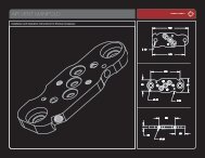
<strong>EPIPHANY</strong> PARTSIMPORTANTFIG. 16MAJOR <strong>EPIPHANY</strong> COMPONENTS1 2 3 4519618781617Although many Ion parts are compatible with theEpiphany, the Epiphany operates in a differentpressure range. For proper operation both anEpiphany Circuit board and Epiphany hoses mustbe used. The Epiphany circuit board can be identifiedby the red protective wrapping with a blackIon logo on its solenoid coil. An Epiphany circuitboard may be used in an Epiphany, Ion or SP-8.Epiphany hoses are rated for higher operatingpressure than standard Ion hoses and are blackin color.9142015111013121 FRKJFSLV–Freak Jr. Front (silver)2 FRKJB30BL–Freak Jr. Back (Ion/Impulse Thread)3 Inner Body Assembly4 EPY101BLK–Epiphany Outer Body Shell (Black Accent)5 ION117UPRVSN–Break Beam Vision Board6 EPY117LOVSNUSASM–Epiphany Curcuit Board Assembly7 EPY108–Epiphany Power Button8 GRPEPYBLK–Rubber Grip (Black Accent)9 SCRN0632X0188BS–Rubber Grip Screws10 9-Volt Alkaline Battery11 SCRN1032X0438SCS–Air Rail Lock Screw12 VLVDTADSLV – On/Off ASA (Silver)13 13 HOS14BLK -1/4” Macro-Line (Black)14 ERG106BLK–Epiphany Regulator Assembly15 SCRN1032X0750CS – Epiphany Grip Frame Screws16 EPY106ASM – Epiphany Grip Frame Assembly17 EPY107ASM – Epiphany Trigger Assembly18 SCRN0832X0313SVS – Conical Trigger Bearing Screws (2)19 SCRN1032X0500VO – Body Flat Cap Screw20 ION120–Filter Screen800.922.2147 www.smartparts.com13
DISASSEMBLY<strong>EPIPHANY</strong> DISASSEMBLY01 0203Before beginning any maintenance or repair procedures,completely unload and degas the markerfollowing the instructions in the Degassingsection of this manual. Choose a clean, stableand protected work area where small parts willnot be lost, such as a table covered with a towelto prevent parts from rolling. Remove the barrel.Use a 1/8-inch allen wrench toremove the body flat cap screwwhich is normally concealed bythe barrel.Remove both left side (gauge side) grip screwswith a a 5/64-inch allen wrench and open theflexible wraparound grip. It is important to notethat the Epiphany’s grip screws are shorter thanthose of an Ion, and use of screws that are toolong may damage the marker’s circuit board.Remove the battery from the grip frame. Graspthe battery in one hand and with the other handgrasp the battery clip by the sides and unplugit from the battery. Remove the right side gripframe screws and the flexible grip, as the upperright grip screw may catch on the circuit board,making its removal difficult.Remove the front and rear gripframe screws using a 5/32-inchallen wrench.FIG. 17POWER BUTTON REMOVALDo not pull on the battery wires or circuit boardto unplug the battery as this may cause significantdamage.[ CONTINUED ON PAGE 15 ]During normal maintenance the power buttondoes not need to be and should not be removed.If it is damaged or requires replacement, grip itbetween a fingernail and thumbnail, and wiggleout, rear side first.14800.922.2147 www.smartparts.com
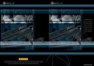
DISASSEMBLYDISASSEMBLY CONTINUED04050607Grasp the body with one hand and the gripframe with the other. Slowly pull the bodyaway from the grip frame, rolling it slightly tothe side, exposing the top of the grip frameand banjo fitting. It can be helpful to gentlypush on the bottom of the circuit board with athumb, helping it to slide upward.Remove the front banjo fitting from over thevertical adapter with a 1/8-inch allen wrench.The center of the banjo fitting will turn with thewrench, pivoting inside the rest of the fitting.Gently complete the process of separatingthe body from the grip frame.Take care to make sure that the circuitboard slides out of the grip frame withoutbeing strained, and that the batterywires and battery clip follow withoutcatching on the grip frame. Set the gripframe aside, and hold the body upsidedown (with the feedneck facing down.)Locate the Vision wiring harness. Thisgroup of four black wires runs fromthe lower circuit board to the Visioncircuit board in the body breech.Unplug the Vision wiring harness fromthe body end, being careful not tostrain the wires by tugging on them.As much as possible, pull on the connectordirectly.08091011Remove the remaining two banjo fittingsfrom the body with a 1/8-inchallen wrench.Keeping the body upside down, slidethe inner receiver components out ofthe body cover.Remove the Vision circuit board from the body breechand set aside carefully. This circuit board is shapedlike the letter C, and should come easily out of place.Take care to make sure that the infra-red emitter anddetector (these look like clear LEDs) are not set onanything that can scratch them.Unscrew the body breech from the firechamber, and remove the bolt from inside.If the bolt stop does not come outwith the bolt, pull it out with a finger.800.922.2147 www.smartparts.com15
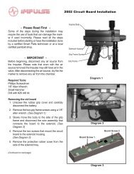
REASSEMBLYCLEANING AND REASSEMBLY01 02 03 04 0506Use a soft cloth toclean all parts ofpaint and dirt as wellas old oil or grease.Make sure the Vision circuit board andits components are clean and undamaged.Make sure no dirt or debris isblocking the Vision holes in the bodybreech – use a cotton swab to cleanthese openings if necessary.Use SL33K togrease all of theo-rings on thebolt and bolt stop.Apply only a thincoating, do notover-grease.Place the bolt stop inside the firechamber and make sure the firechamber insert is fully seated. Makesure the concave side of the bolt stop(shaped like the inside of a cone)faces the back of the marker.Slide the bolt into thebolt stop inside the firechamber until it stops.Screw the fire chamber intothe body breech. Place theVision circuit board into itsslot in the body breech. Itsplug should be on the sideof the board facing the rearof the marker. The clearemitter and detector shouldbe on the side facing thefront of the body breech.07 0809 10If necessary, rotate theswivel donut so that itsscrew holes are on thebottom of the receiver,lined up with the screwholes in the body breech.Slide the inner receiver assembly into the body cover whileholding both upside down to prevent the Vision circuitboard from falling out, then plug the Vision wire harnessback into the Vision circuit board, and reconnect the centerand rear banjo fittings to the receiver, being careful not tocross thread them.Carefully pass the battery clip down into thegrip frame and slide the circuit board intoplace before reinstalling the forward banjofitting to its position in the grip frame, againtaking care not to cross-thread.Reposition the body and grip frame togetherbeing careful not to pinch any wires or hoses.Reinstall the grip frame screws, and flat capbody screw, then tighten all three with an 1/8-inch allen wrench. Reinstall the battery, takingcare not to pinch the battery wires, and flexiblethe rubber grip and its screwsFIG. 18INNER BODY ASSEMBLY1 EPY102–Epiphany Body Breech2 EPY103–Epiphany Feed Tube3 ORN02552070BU – Feed Tube Friction O-rings4 ION209–Fire Bolt5 ION111 – Bolt Stop6 EPYINTS–Small Epiphany Insert (Silver)7 EPYINTM–Medium Epiphany Insert (Blue)8 EPYINTL–Large Epiphany Insert (Green)9 EPY104–Epiphany Fire Chamber10 ION110–Swivel Donut11 CLP004–Donut Clip12 ORN01790UR–SFT O-Ring13 ION108–Ball Detent (2x)14 ORN01770HN–Rear Breech O-Ring15 ION117UPRVSN-Break-Beam Vision Board16 ORN02270BU–Body Breech Friction O-Ring17 ORN02070BU–Body Breech Seal O-Ring18 ORN01590CUR–Firebolt Bumper19 ORN0162070HN–Firebolt Middle O-Ring20 ORB01070UR–Firebolt Rear O-RIng21 ORN01470UR–Bolt Stop Inner O-Ring22 ORN02070BU–Bolt Stop Outer O-Ring23 ORN01570BU X–Swivel Donut O-Rings (2x)16800.922.2147 www.smartparts.com
<strong>EPIPHANY</strong> VOLUME INSERTSIMPORTANTIn order to provide more consistent velocity at higher rates of fire (above 10 bps) the Epiphany utilizes asmaller fire chamber volume than an Ion. To deliver full velocity, it operates at a slightly higher pressurerange (250 to 280 psi.) The smaller volume fire chamber can be recharged more quickly by the regulator,while the Ion bolt structure ensures that only a gentle low pressure burst of gas impacts against thepaintball.In order to tune the Epiphany for optimal performance, three inserts are available, allowing four levelsof adjustment to the volume of the fire chamber. These range from the largest volume (no insert,) to thegreen insert (second largest volume) to the blue insert (second smallest volume,) and finally to the silverinsert (smallest volume.) An increase in operating pressure can be balanced with a decrease in firechamber volume to maintain desired velocity.COMMON <strong>EPIPHANY</strong> CONFIGURATIONS:Choosing the ideal insert and operating pressure level is a balancing act between lower pressures whichallow for gentler, quieter operation with longer hose life in high temperatures, and high pressures whichallow for better velocity consistency at high rates of fire (10 bps and above.) While some experimentationwill be necessary to find the best settings for any given marker configuration and playing conditions,the following guidelines will help select the proper volume insert.Stock Epiphany bolt (Firebolt) and a Quick Exhaust Valve (QEV) – Blue (middle size) Volume Insert – Thevolume of the blue insert will compensate for the volume of gas in the Firebolt’s air spaces, to provide300 fps operation at approximately 260 psi.Stock Epiphany Bolt without QEV – No Volume Insert – The entire volume of the Epiphany fire chamber isutilized to deliver a velocity of 300 fps at approximately 260 psi.Reducing Pressure – Green Insert (thinnest wall, high gas volume) – If the pressure at the desired velocityis above the Epiphany’s maximum of 280 psi, or temperatures are extremely high (which can softenpneumatics hoses) an increase in fire chamber volume to reduce operating pressure can be desirable.Indoor Operation – Silver Insert (thickest wall – smallest gas volume) – Many indoor paintball fieldsrestrict marker velocity to a maximum of 250 fps. By reducing the fire chamber volume even further, thesilver insert allows this velocity to be reached while keeping the fire chamber pressure up in the range of250-280 psi, protecting against velocity drop-off under rapid fire conditions.FIG. 19REMOVING VOLUME INSERTCHANGING VOLUME INSERTSChanging the volume inserts is simple. Degasand disassemble the Epiphany, followingthe Disassembly section of this manual. Theselected insert (or no insert) can be slid freelyinto the Epiphany fire chamber, and installedinserts can be removed by reaching a fingerinto the insert and pulling it out. After installingthe proper insert, the Epiphany can be reassembledby following the Reassembly sectionof this manual. The marker will then need tobe set to the optimal dwell setting (see thedwell section of this manual) and have itsvelocity measured and set (see the Velocitysection of the this manual.)800.922.2147 www.smartparts.com17
SOLENOID VALVEDISASSEMBLY AND MAINTENANCEFIG. 20SOLENOID EXPLODED VIEW1 BUM006 – Foam Disk2 ION118 – Vision Wiring Harness3 ELB1032X18PTCBNJ – Banjo Fitting4 ELB1032X532PTCBNJ – Banjo Fitting5 HOS4MMBLK4025 – Black Epiphany Hose6 EPY117LOVUSASM – Epiphany Circuit Board7 HOS4MMBLK875 – Black Epiphany Hose8 ELB1032X532PTCBNJ – Banjo Fitting9 Armature10 SOL3UPG – Epiphany Solenoid Coil11 Solenoid Head12 Solenoid BracketThe solenoid valve is the heart of the Epiphany.When the circuit board supplies it with power, itredirects gas flow to allow the bolt to close andfire the marker. During normal maintenance thesolenoid valve should not need to be disassembled.However, if it becomes clogged ordevelops a leak it is simple to disassemble forcleaning or repair. When replacing hoses orsolenoid valve components, Epiphany specificmodels must be used. The Epiphany solenoidvalve can be identified by its red protective coilwrap with black Ion logo.01 02 03 04 05 0607Follow the disassembly instructionsto remove the circuit boardfrom the Epiphany. Using a 3/32-inch allen wrench, hold the circuitboard and solenoid body thenpry the bracket from the backof the solenoid valve. Place thewrench between the bracket andthe upper, black section of thesolenoid valve body.Do not pry against the redsolenoid coil or the Epiphanyheat shrink coil protector, asthis will cause damage.After the solenoidbracket isremoved, lift thesolenoid headstraight out, wigglingif necessaryto loosen it.Tip the circuitboard over and allowthe armatureto fall into yourhand. The armaturefits loosely inthe center of thecoil, and shouldfall out easily.Clean the insideof the solenoidwith a cottonswab, and cleanthe armaturewith a soft cloth,removing any debris,oil or grease.Reassemblethe solenoidvalve. Place thearmature back inthe coil with thearmature facingdown.Push the solenoidhead back intothe solenoid valvebody, makingsure that the longhoses and Visionwiring harnessare aligned on thesame side of thecircuit board asthe trigger switch.Replace the solenoid bracket,pressing it back into place. Thebent bracket section goes overthe bottom side of the solenoid.A very light layer of SL33K lubricatingthe hose barb will makethe installation of new hoseseasier, but extreme care must betaken that no excess grease isable to enter the solenoid valve.Holding the solenoid head witha box end or small adjustablewrench over the hose barb willallow the hose to be pulled awayfrom the wrench which will holdback the solenoid head.18800.922.2147 www.smartparts.com
REGULATORNote: When removing or installing the Epiphanyregulator, it is important to pull down firmly onthe regulator sleeve so that the regulator bodyturns with it.01 02 03 04FIG. 21REGULATORParts of the Epiphany’s verticalregulator use left-handedthreads. These parts must beturned counter-clockwise toscrew them in, and clockwiseto unscrew them – the oppositedirection of normal screws.Degas the marker, and removethe macroline hose from theregulator. Unscrew the regulatorfrom the Epiphany’s verticalASA. Remove and clean themetal filter screen which islocated between the regulatorand the vertical ASA. Slide theregulator body out of its sleeve.This sleeve is metal, and frictionfit to the regulator body with ano-ring.Use a 5/8-inch open-end wrenchor adjustable wrench to turn theadjuster cap on the bottom of theregulator, as if you were adjustingvelocity, until the safety screw isvisible in the vertical safety screwslot. The safety screw ensuresthat the regulator will not beunscrewed too far during normaluse. Use a 3/32-inch Allen wrenchto remove the safety screw.The adjuster cap is left-handthreaded. Turn it clockwise tounscrew it from the vertical regulatorbody. Use the open end oradjustable wrench to completelyremove the adjuster cap.05060708Locate the lock screw halfway up theside of the regulator body, and removeit with a 3/32-inch Allen wrench. Thelock screw secures the spring platformin place. Now that it is unlocked, use a9/16-inch deep well socket and ratchet toremove the spring platform by unscrewingit clockwise (the spring platform isalso left-hand threaded.) The hex faceson the spring platform are short, so youwill need to exert a steady pressure onthe socket to maintain contact.The regulator spring should fall easilyout of the regulator body oncethe spring platform is removed.The Regulator piston may requirelight pressure from an allenwrench through the top of theregulator body for removal. Usea gentle hand here, as the brassof the regulator piston can bescratched by hard tools.09 10When the spring platform is fully seated, it will be visible through thelock screw hole in the side of the regulator. Lock it in place by reinstallingthe lock screw. Reinstall the pressure adjuster cap by screwing itcounter-clockwise into the regulator body. Turn it until the safety screwaligns with the safety screw slot. Put a small amount of blue Loctite242 threadlocker or equivalent (even clear fingernail polish can do in apinch) on the safety screw. Reinstall the safety screw.Clean all of the regulator parts witha soft cloth or paper towel. Inspectall o-rings and the regulator seat(the clear part on the end of thepiston) for damage, and replace ifnecessary. Lubricate the o-ringson the piston assembly withSL33K.Do not lubricate the regulator seator the o-ring on the adjuster cap.Place the regulator spring onthe regulator piston assembly.Hold the regulator body ASAside down, and slide the twoparts into the body. Lowerthe spring platform into theregulator body nut side up,and use the 9/16-inch deepwell socket to screw it intoplace with a counter-clockwisemotion.Place the sleeve o-ring inside the sleeve, followed by the regulator.Do not lubricate the sleeve or its o-ring, or the regulator will becomeextremely difficult to remove from the Epiphany. Reinstall the regulatorinto the vertical ASA of the Epiphany. Reconnect the macroline,and be sure to use a chronograph to re-adjust the Epiphany’s velocitybefore use.1 ERG106BLK – Epiphany Reg Cover (Black Accent)2 ORN02270BU – Epiphany Reg Cover Friction o-ring3 ORN01590UR – ASA o-ring4 SCRN1032X125SCO – Lock Screw5 IRG101 – Epiphany Regulator Body6 SCRN0440X0188CO – Safety Screw7 IRG105ASM – Piston Assembly8 SPR030 – Epiphany Reg Spring9 IRG102 – Spring Platform10 IRG104ASM – Pressure Adjuster CapBe certain that the safety screw is fully seated and the adjuster cap canturn freely.Service and adjustments to the regulator will cause changes in itsoutput pressure. Adjust the regulator to deliver between 250 and280 psi then repeat the velocity adjustment procedure.800.922.2147 www.smartparts.com19
BALL DETENTSINSPECTION, CLEANING AND REPLACEMENT01 02 03 04 05Degas and disassemblethe marker (seedisassembly section.)Look into the body breech.The tip of each ball detentshould extend approximately1/16 of an inch intothe breech area. If eitherdetent does not reachthis far into the breech, itshould be replaced.To avoid risk of eyeinjury, even while wearinggoggles, do not look intothe barrel or breech of anassembled marker.Reach a finger into thebody breech and pressout against the detent. Itmay then be removed byprying or gripping withfingernails, needle-nosedpliers, an o-ring pick or evena 0.050-inch allen wrench.Inspect the ball detents fortears or damage. If they aredamaged, replace them. Ifnot, clean them with a softcloth, and clean the detentopenings in the body breechwith a cotton swab.Reinstall the detents bypressing them into placewith a thumb.Reassemble the marker.FIG. 22PRYING OUT DETENT20800.922.2147 www.smartparts.com
TROUBLESHOOTINGIMPORTANT<strong>EPIPHANY</strong> IS LEAKING INTERNALLY.— Pneumatic hoses may be loose, damaged or not fully connected. Replace hoses with Smart PartsEpiphany hoses only.— One or more of the banjo fittings may be loose or have a damaged seal. Inspect and tighten fittings.Replace if necessary with Smart Parts Ion/Epiphany banjo fittings only.— Solenoid armature is damaged or overpressurized. Make sure operating pressure is under 280psi. Inspectsolenoid valve and replace armature if necessary.— Incorrect solenoid valve may be overpressurized. The Epiphany and Epiphany rated Blackheart solenoidvalves can be identified by a red protective wrap with a black Ion logo. Standard Ion/SP-8 (no coilwrap,) Pre-Epiphany Blackheart (black wrap with red logo) or after-market solenoid valves may not functionproperly in the Epiphany’s pressure range.<strong>EPIPHANY</strong> IS LEAKING DOWN THE BARREL.— One or more of the bolt o-rings and/or the bolt stop o-rings are damaged. Inspect and replace.<strong>EPIPHANY</strong> IS LEAKING FROM THE MACROLINE AIR FITTINGS.— Macroline may not be fitted properly. Degas the marker and make sure the macroline is properlylocked into its fittings. If the macroline shows signs of damage, replace it with a new piece. Be sure tocut clean ends, and if using diagonal cutters, dress the end with a small needle file to be certainit is not crimped partially closed.<strong>EPIPHANY</strong> IS LEAKING FROM IN OR AROUND THE REGULATOR.— The ASA o-ring at the top of the regulator may be damaged. Remove the regulator to inspect. Ifthis o-ring is damaged it may be replaced with a standard CO 2bottle o-ring available at mostpaintball shops.— The regulator seat may be contaminated and/or damaged. Inspect and clean the regulator seat(see Regulator section of this manual.) If the regulator seat is damaged, it may be flipped over touse the back side. If both sides are damaged, it must be replaced.<strong>EPIPHANY</strong> EXHIBITS FIRST SHOT DROP-OFF (FSDO).— FSDO is a low velocity, or non-firing first shot followed by normal shooting, and is often caused bydebris in the bolt or a poorly lubricated bolt. Clean the bolt, body breech, fire chamber and boltstop, and lubricate them with SL33K (See the Disassembly section of this manual.)— FSDO can also be caused by too low of a dwell setting. Follow the procedure for optimal dwell adjustmentand or increase the dwell setting (see the Electronic Adjustment section of this manual.)800.922.2147 www.smartparts.com21
TROUBLESHOOTINGIMPORTANT<strong>EPIPHANY</strong> HAS INCONSISTENT VELOCITY OR DROPS SIGNIFICANTLY DURING RAPID FIRING.— Barrel to paint match may not be correct. Check the fit of the paintballs to the barrel (see Paint sectionof this manual.) If it is a poor fit, switch paintballs, barrel, or barrel insert for a better fit.— Gas source could be low. Fill gas source and make sure valve is turned on.— Battery may be low. This will be most noticeable with velocity dropping, and then entire shots not firingduring rapid fire. Replace with a name brand alkaline 9-volt battery.— Regulator seat may be contaminated and/or damaged. Inspect and clean the regulator seat (seeRegulator section of this manual.) If the regulator seat is damaged, it may be flipped over to use theback side. If both sides are damaged, it must be replaced.— Pressure may be low. Switch to a smaller volume fire chamber insert and increase operating pressure.— SFT o-ring may be damaged, swollen or missing. Inspect and if necessary replace the SFT o-ring(see Assembly diagram.)— Liquid CO 2may be entering the regulator. Only use CO 2with an anti-siphon tank in the ASA, or astandard tank placed vertically in a pack with a remote. Alternatively, switch to compressed air.<strong>EPIPHANY</strong> WILL TURN ON BUT WILL NOT FIRE.— Battery may be low or dead. Replace with a name brand alkaline 9-volt battery.— Solenoid valve may be blocked with debris. Disassemble solenoid, clean armature, and inside solenoidbody, then reassemble without lubricant (see Solenoid Disassembly/Maintenance sectionof this manual.)— One or more of the trigger set screws may be mis-adjusted. The trigger switch should be heard clickingwhen the trigger is pulled with the Epiphany turned off. Back pre and post-travel screws out untiltrigger will activate the marker then set properly (See the Trigger section of this manual.)— Trigger switch may be damaged. - Visit your nearest Smart Parts Authorized Dealer or contact SmartParts for circuit board repair or replacement.— Regulator output pressure may be too high (above 280 psi) Decrease the pressure (see VelocityAdjustment section of this manual.) If pressure slowly rises after being set, inspect, clean and ifnecessary replace the regulator seat (See Regulator section of this manual.)— Liquid CO2 may be entering the regulator. Only use CO2 with an anti-siphon tank in the ASA, or astandard tank placed vertically in a pack with a remote. Alternatively, switch to compressed air.TRIGGER WILL NOT RESET TO THE FORWARD POSITION— The trigger activation point screw may be adjusted too far toward the rear of the marker. Follow thetrigger adjustment instructions and adjust this screw further in to the trigger.22800.922.2147 www.smartparts.com
TROUBLESHOOTINGIMPORTANT<strong>EPIPHANY</strong>’S POWER BUTTON LIGHT FLASHES IN VISION MODE BUT WILL NOT FIRE.— Possible chamber obstruction. Hold the power button down to put the Epiphany into non-Visionmode. While wearing paintball mask/googles in an area where it is safe to fire, fire the marker to clearany possible chamber obstructions.— Paint or debris may be blocking the Vision eye from “seeing” the breech. Remove the Vision circuitboard. Carefully clean the infrared emitter and detector with a damp, soft cloth and clean the Visionports in the body breech with a cotton swab (see Disassembly section of this manual.)— Wiring harness may be disconnected. Check to make sure that the wiring harness running from thesolenoid circuit board in the grip frame to the Vision circuit board in the body is plugged in at bothends, and is not bent, crimped, broken or frayed (See Disassembly section of this manual.)— Vision reflector may be damaged or missing. Inside of polymer Ion body covers (if you are runningyour Epiphany incognito) on the right hand side is a reflective mylar sticker. This sticker must be cleanand intact for proper Vision operation.THE <strong>EPIPHANY</strong> IS BREAKING PAINT.— Battery may be low or dead. Replace with a name brand 9-volt alkaline battery.— Ball detents may be worn or damaged. Inspect and if necessary replace (See Ball Detent section ofthis manual.)— Barrel to paint match may not be correct. Check the fit of the paintballs to the barrel (see Paint sectionof this manual.) If it is a poor fit, switch paintballs, barrel, or barrel insert for a better fit.— Dwell setting may be too high. Lower the dwell setting in three click increments and retest, or reset tothe optimum dwell value (see the Dwell section of this manual.)— Vision mode may be turned off. This will be indicated by a double-blink pattern on the power button.Turn Vision on by pressing the power button.— Paint or debris may be partially blocking the Vision eye from properly “seeing” the breech. Removethe Vision circuit board. Carefully clean the infrared emitter and detector with a damp, soft cloth andclean the Vision ports in the body breech with a cotton swab (see Disassembly section of this manual.)— Vision reflector may be damaged or missing. Inside of plastic body covers, on the right hand side is areflective mylar sticker. This sticker must be clean and intact for proper Vision operation.— Wiring harness may be damaged. Check to make sure that the wiring harness running from the solenoidcircuit board in the grip frame to the Vision circuit board in the body is plugged in at both ends,and is not bent, crimped, broken or frayed (See Disassembly section of this manual.)— Vision board may be damaged from improper installation. Replace Vision board (See Disassemblysection of this manual.)— Liquid CO 2may be entering the regulator. Only use CO 2with an anti-siphon tank in the ASA, or astandard tank placed vertically in a pack with a remote. Alternatively, switch to compressed air.800.922.2147 www.smartparts.com23
TROUBLESHOOTINGIMPORTANTROF IS TURNED UP ALL THE WAY AND <strong>EPIPHANY</strong> WILL NOT FIRE RAPIDLY.— The ROFDelay setting of the Epiphany circuit board controls how long the marker must wait betweenshots. Increasing the delay (yellow blinking) will slow the Epiphany down. Decreasing thedelay (red blinking) will allow it to shoot faster (see Electronic Adjustment section of manual.)— The Epiphany’s break-beam Vision system prevents it from firing until a paintball has been properlyloaded. Non-motorized or agitating hoppers will not feed paintballs as quickly as a modern forcefeedloader, resulting in a restricted rate of fire.AFTER DISASSEMBLING THE <strong>EPIPHANY</strong>,THE GRIP FRAME AND BODY BREECH FLAT TOP SCREWHOLES NO LONGER LINE UP CORRECTLY WITH THE GRIP FRAME.— If the bolt stop is installed backwards during re-assembly, the body breech can not screw all theway into the fire chamber. This will prevent the two parts from sealing properly and change thealignment of screw holes to the grip frame. Reinstall the bolt stop with the concave surface facinginto the fire chamber.A REFEREE SAYS THE <strong>EPIPHANY</strong> IS SHOOTING TOO FAST (BALLS PER SECOND)— Some tournaments and paintball fields limit the rate of fire allowed. Many tournaments, for example,limit players to a maximum of 15 balls per second. The marker’s rate of fire can be limited byincreasing the ROFDelay setting (see Electronic Adjustment section of manual and the CPS Table.)REFEREE SAYS THE <strong>EPIPHANY</strong> IS SHOOTING TOO FAST (MORE THAN 1 SHOT PER TRIGGER PULL)— Many tournaments, scenario games and paintball fields limit players to shooting in true semi-automaticmode. Set the marker’s firing mode to 0-Semi-Automatic (see Electronic Adjustment sectionof manual.)A REFEREE SAYS THE <strong>EPIPHANY</strong> NEEDS A TOURNEY CAP.— Tournaments, scenario games and paintball fields all require that a paintgun’s velocity may not beadjusted without tools, and do not allow tools on field. While it is extremely difficult, some refereesmay claim that a very strong person will be able to adjust the Epiphany’s regulator with bare hands.These referees may require that an additional locking device be used. A velocity locking cap is availablefor Smart Parts Authorized Dealers to further secure the regulator setting.TECH SUPPORTOur Technical Support Department is openMonday through Friday, from 10am to 6pmEST, and can be reached at 724-539-2660.Additional support and downloadable productmanuals are available through our web site,www.smartparts.com.WARRANTYSmart Parts warrants for one (1) year to initial retailpurchaser that the paintball marker and regulator are freefrom defects in materials and workmanship. Disposableparts (batteries, o-rings, seals, etc.) are not warranted.The valve assembly is warranted for six (6) months. Thesolenoid and electronics on the marker are warranted forsix (6) months, plus an additional warranty of six monthsfor electronic parts only (installation and labor are notincluded.) This warranty does not cover surface damages(scratches and nicks), misuse, improper disassemblyand re-assembly, attempts made to drill holes or removemetal from the external surfaces which could degradeperformance and reduce pressure safety factors of themarker. Do not make changes to the basic marker partswithout written approval. The only authorized lubricant forthe marker is SL33K Lubricant. Use of any other lubricantcould result in voiding your warranty. Paintball markersare non-refundable. This warranty is limited to repairor replacement of defective parts with the customer topay shipping costs. This warranty is effective only if thecustomer returns the warranty registration card enclosedwith the marker. The warranty is non-transferrable. Do notattempt to alter the trigger assembly in any way, as thiswill void your Smart Parts Inc. warranty. Trigger alterationof any kind may result in serious injury.24800.922.2147 www.smartparts.com
CPS TABLEThis table provides a cross reference between Epiphany settings and the resulting maximumpossible cycles per second. To limit an Epiphany to shoot at or below 15 balls persecond, look up its dwell setting in the dwell column, then look across to find a CPS valuethat is comfortably below 15, and up to find the appropriate ROFDelay value needed.Stock Dwell Value: 52 clicks from bottomStock ROFDelay Value: 50 clicks from bottomROFDELAYD W E L LNOTE: THE <strong>EPIPHANY</strong> CIRCUIT BOARD WILL WILL NOT FIRE FIRE AT AT A MAXIMUM RATES ABOVE OF 17 CYCLES PER SECOND.Clicks 0 5 10 15 20 25 30 35 40 45 50 55 60 65 70 75 80 85 88Clicks Ms 8 10.5 13 15.5 18 20.5 23 25.5 28 30.5 33 35.5 38 40.5 43 45.5 48 50.5 520 25.0 17.0 17.0 17.0 17.0 17.0 17.0 17.0 17.0 17.0 17.0 17.0 16.5 15.9 15.3 14.7 14.2 13.7 13.2 13.03 26.5 17.0 17.0 17.0 17.0 17.0 17.0 17.0 17.0 17.0 17.0 16.8 16.1 15.5 14.9 14.4 13.9 13.4 13.0 12.76 28.0 17.0 17.0 17.0 17.0 17.0 17.0 17.0 17.0 17.0 17.0 16.4 15.7 15.2 14.6 14.1 13.6 13.2 12.7 12.59 29.5 17.0 17.0 17.0 17.0 17.0 17.0 17.0 17.0 17.0 16.7 16.0 15.4 14.8 14.3 13.8 13.3 12.9 12.5 12.312 31.0 17.0 17.0 17.0 17.0 17.0 17.0 17.0 17.0 16.9 16.3 15.6 15.0 14.5 14.0 13.5 13.1 12.7 12.3 12.015 32.5 17.0 17.0 17.0 17.0 17.0 17.0 17.0 17.0 16.5 15.9 15.3 14.7 14.2 13.7 13.2 12.8 12.4 12.0 11.818 34.0 17.0 17.0 17.0 17.0 17.0 17.0 17.0 16.8 16.1 15.5 14.9 14.4 13.9 13.4 13.0 12.6 12.2 11.8 11.621 35.5 17.0 17.0 17.0 17.0 17.0 17.0 17.0 16.4 15.7 15.2 14.6 14.1 13.6 13.2 12.7 12.3 12.0 11.6 11.424 37.0 17.0 17.0 17.0 17.0 17.0 17.0 16.7 16.0 15.4 14.8 14.3 13.8 13.3 12.9 12.5 12.1 11.8 11.4 11.227 38.5 17.0 17.0 17.0 17.0 17.0 16.9 16.3 15.6 15.0 14.5 14.0 13.5 13.1 12.7 12.3 11.9 11.6 11.2 11.030 40.0 17.0 17.0 17.0 17.0 17.0 16.5 15.9 15.3 14.7 14.2 13.7 13.2 12.8 12.4 12.0 11.7 11.4 11.0 10.933 41.5 17.0 17.0 17.0 17.0 16.8 16.1 15.5 14.9 14.4 13.9 13.4 13.0 12.6 12.2 11.8 11.5 11.2 10.9 10.736 43.0 17.0 17.0 17.0 17.0 16.4 15.7 15.2 14.6 14.1 13.6 13.2 12.7 12.3 12.0 11.6 11.3 11.0 10.7 10.539 44.5 17.0 17.0 17.0 16.7 16.0 15.4 14.8 14.3 13.8 13.3 12.9 12.5 12.1 11.8 11.4 11.1 10.8 10.5 10.442 46.0 17.0 17.0 16.9 16.3 15.6 15.0 14.5 14.0 13.5 13.1 12.7 12.3 11.9 11.6 11.2 10.9 10.6 10.4 10.245 47.5 17.0 17.0 16.5 15.9 15.3 14.7 14.2 13.7 13.2 12.8 12.4 12.0 11.7 11.4 11.0 10.8 10.5 10.2 10.148 49.0 17.0 16.8 16.1 15.5 14.9 14.4 13.9 13.4 13.0 12.6 12.2 11.8 11.5 11.2 10.9 10.6 10.3 10.1 9.951 50.5 17.0 16.4 15.7 15.2 14.6 14.1 13.6 13.2 12.7 12.3 12.0 11.6 11.3 11.0 10.7 10.4 10.2 9.9 9.854 52.0 16.7 16.0 15.4 14.8 14.3 13.8 13.3 12.9 12.5 12.1 11.8 11.4 11.1 10.8 10.5 10.3 10.0 9.8 9.657 53.5 16.3 15.6 15.0 14.5 14.0 13.5 13.1 12.7 12.3 11.9 11.6 11.2 10.9 10.6 10.4 10.1 9.9 9.6 9.560 55.0 15.9 15.3 14.7 14.2 13.7 13.2 12.8 12.4 12.0 11.7 11.4 11.0 10.8 10.5 10.2 10.0 9.7 9.5 9.363 56.5 15.5 14.9 14.4 13.9 13.4 13.0 12.6 12.2 11.8 11.5 11.2 10.9 10.6 10.3 10.1 9.8 9.6 9.3 9.266 58.0 15.2 14.6 14.1 13.6 13.2 12.7 12.3 12.0 11.6 11.3 11.0 10.7 10.4 10.2 9.9 9.7 9.4 9.2 9.169 59.5 14.8 14.3 13.8 13.3 12.9 12.5 12.1 11.8 11.4 11.1 10.8 10.5 10.3 10.0 9.8 9.5 9.3 9.1 9.072 61.0 14.5 14.0 13.5 13.1 12.7 12.3 11.9 11.6 11.2 10.9 10.6 10.4 10.1 9.9 9.6 9.4 9.2 9.0 8.875 62.5 14.2 13.7 13.2 12.8 12.4 12.0 11.7 11.4 11.0 10.8 10.5 10.2 10.0 9.7 9.5 9.3 9.0 8.8 8.778 64.0 13.9 13.4 13.0 12.6 12.2 11.8 11.5 11.2 10.9 10.6 10.3 10.1 9.8 9.6 9.3 9.1 8.9 8.7 8.681 65.5 13.6 13.2 12.7 12.3 12.0 11.6 11.3 11.0 10.7 10.4 10.2 9.9 9.7 9.4 9.2 9.0 8.8 8.6 8.584 67.0 13.3 12.9 12.5 12.1 11.8 11.4 11.1 10.8 10.5 10.3 10.0 9.8 9.5 9.3 9.1 8.9 8.7 8.5 8.487 68.5 13.1 12.7 12.3 11.9 11.6 11.2 10.9 10.6 10.4 10.1 9.9 9.6 9.4 9.2 9.0 8.8 8.6 8.4 8.390 70.0 12.8 12.4 12.0 11.7 11.4 11.0 10.8 10.5 10.2 10.0 9.7 9.5 9.3 9.0 8.8 8.7 8.5 8.3 8.2800.922.2147 www.smartparts.com25
800.922.2147 100 Station St. Loyalhanna, PA 15661 www.smartparts.com manual version 1.0