
You also want an ePaper? Increase the reach of your titles
YUMPU automatically turns print PDFs into web optimized ePapers that Google loves.
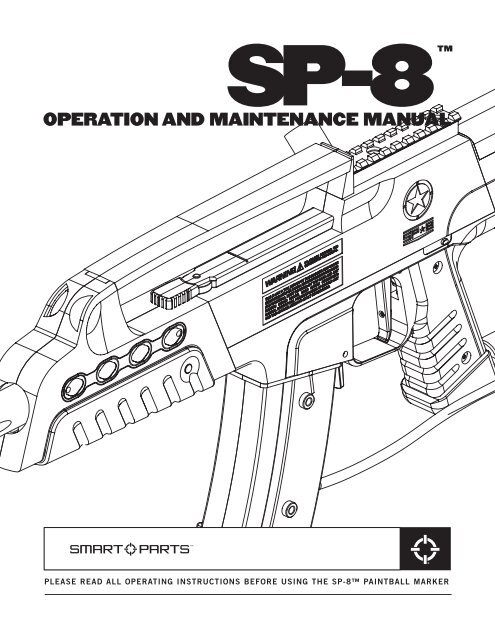
SP-8OPERATION AND MAINTENANCE MANUALPLEASE READ ALL OPERATING INSTRUCTIONS BEFORE USING THE SP-8 PAINTBALL MARKER
WARNING— WE STRONGLY RECOMMEND AN ANTI-SIPHON TUBE WITH CO 2 TANKS.— Exceeding 200psi inlet pressure to the SP-8 voids the product warranty.— Do not replace any internal hose with any brand other than Smart Parts.— Do not use any type of hose clamp or overheat internal hoses—this canweaken and damage them.— Do not grease or oil the solenoid internals—this will cause it to jam.— When storing the SP-8 for an extended amount of time, disconnect andremove the battery to prevent draining it.SP-8 QUICK START1. Screw on the barrel, then place a barrel cover over the end of the barrel.2. Screw your air source into the SP-8’s bottom line. If using Nitrogen/Compressed air, simply screw your tank in until it seals. If using CO2, besure to only use a tank with an anti-siphon tube. Failure to use an antisiphontube will cause a major decrease in performance and/or cause sealdamage to your SP-8. We also recommend using an on/off valve, as well.3. Place your hopper into the SP-8’s feed tube. Now add paintballs and turnon your loader. Note: An electronic agitating hopper is recommended foruse with the SP-8.4. Making sure your goggles are on, remove the barrel cover. Turn the SP-8on by depressing the POWER button for approximately two seconds. Theon/off switch, which also functions as your safety, is located on the leftside of the marker just above the above the grip and behind the triggerguard. (Figure 1) The switch light will now blink rapidly red (green for UKusers). The SP-8 is now on and in Vision mode.5. The SP-8 is now ready for play. Follow all safety regulations and rulesbefore beginning and during play.NOTE 1: To degas the SP-8 properly and prevent damage to your bottle o-ring, turn the bottleout slowly as you cycle the marker after you have removed the hopper and paintballs. Makesure that there are no paintballs in the marker breach, turn the eyes off, and point the barreltowards the ground with a barrel cover on during removal.CAUTION: THE SP-8’S REGULATOR WILL HOLD ONE TO THREE SHOTS WORTH OF AIRAFTER THE AIR SOURCE HAS BEEN REMOVED. FOR SAFETY, MAKE SURE TO CYCLE YOURSP-8 WITH THE AIR SOURCE COMPLETELY REMOVED UNTIL IT WILL NOT FIRE TO BE CER-TAIN THAT ALL AIR IS OUT OF THE SP-8 AND REGULATOR.
READ OWNER’S MANUAL BEFORE OPERATINGTHIS IS NOT A TOY. MISUSE MAY CAUSE SERIOUS INJURY OR DEATH. EYEPROTECTION DESIGNED SPECIFICALLY FOR PAINTBALL MUST BE WORN BYUSER AND PERSONS WITHIN RANGE. RECOMMEND 18 YEARS OR OLDERTO PURCHASE. PERSONS UNDER 18 MUST HAVE ADULT SUPERVISION.POWER/MODE INDICATORWhen you turn on the SP-8, the red light inside the on/off switch (green for UK circuit boards) willbegin blinking rapidly if there’s a ball present. This indicates your SP-8 is on, in Vision mode, andready to fire. This is the ideal mode for game play.If the light blinks slowly—one blink at a time, the eyes are on,—but the bore is empty. Simply loadthe hopper with paint. Once a ball is present in the breech, the light will begin to blink rapidly.If you tap the switch once more, the light will blink more slowly, in a double blink sequence.This means that the eyes are off, but the SP-8 will still fire. This is the desirable mode for degassingand testing.All other light indicators are covered in the CIRCUIT BOARD SETTINGS/ADJUSTMENT section.MAINTENANCEINCLUDED WITH YOUR SP-8TOOLS YOU WILL NEED.050" Allen Wrench 9/16" deep well socket and ratchet3/32" Allen Wrench Phillips screwdriver1/8" Allen WrenchDouble Open End Wrench (5/8" & 7/16" ends)<strong>Sp</strong>ares parts kitSTATISTICSLength/Weight:Operating Pressure:Propellant:Mode of Fire:Rate of Fire:Efficiency:Dwell Setting:Vision Eye:Power Source:Barrel Thread:Lubricant:21 inches (with stock 14" barrel), 4 lbs. 4 oz.180 psiCO 2 or Nitrogen/Compressed AirFull Auto, 3-shot burst, Semi automatic and Rebound17bps max (Semi & Rebound), 10bps (Auto & 3-shot burst—US board only)1200 shots (68ci, 4500psi tank), 800 shots (20oz. ANTI-SIPHON tank)52 (from bottom)Yes9 volt batteryImpulseUse any paintball approved oil or grease.
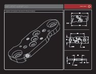
SP-8 ASSEMBLY DIAGRAM
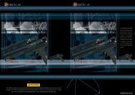
DISASSEMBLY1. Remove barrel, paintballs and hopper. Next remove all air sources to degas SP8.2. The first components to remove are the butt cap and compact shroud. Both parts can be removedby pushing out the silver body pins (PIN012). The pin has a flat head with a dimple on one side.You must push from the opposite side to remove the pin. (see figure 1)3. Inspect body pin orings for any damage. If O-ring are not intact body pins could fall out duringplay. If O-ring are damaged replace with the spares provided.4. Once both pins have been removed you can now pull the compact shroud off of the front of thebody and the butt cap straight off the back of the body. (see figure 2)FIG. 1FIG. 2FIG. 35. Remove both left side grip screws (the side of the marker with the gauge on it), then open thegrip and disconnect the battery. NOTE: ONLY REMOVE THE BATTERY BY SEPARATING THECONNECTOR DIRECTLY FROM THE BATTERY. PULLING ON CIRCUIT BOARD WIRES CAN ANDWILL CAUSE SIGNIFICANT AND EXPENSIVE DAMAGE.6. Remove the front and rear grip frame screws and set aside. Grasp the SP-8 body with one hand,the grip frame with the other. GENTLY AND SLOWLY roll the body from the grip frame until theyou can access the top of the grip frame with an Allen wrench. (see figure 1)7. Using a 1/8" Allen wrench, remove the pneumatic banjo fitting from above the vertical adaptor.(see figure 2)8. Once again, GENTLY AND SLOWLY finishseparating the the body from the grip framethen set grip frame aside. Turn the body upsidedown, then remove the Vision wire harnessfrom the body. Next, remove the remaining twobanjo fittings with your 1/8" Allen Wrench.9. While still keeping the body upside down,slide the metal sleeve out of the compositeouter shell. Remove the Vision eye board bylifting straight up with your index finger andthumb. The Vision eye board is roughly c-shaped with one eye on either point of the “C”.(see figure 3)10. Disassemble the front and rear metal body sections from each other by simply unscrewing themfrom each other. All that now remains are the bolt and bolt stop which are located in the rear halfof the body assembly. Begin pulling out the bolt, then shift the bolt to the side to catch the endunder the edge of the bolt stop. Pull until both the bolt and bolt stop are removed.NOTE: SEE NEXT PAGE FOR FURTHER DISASSEMBLY OF THE UPPER RECEIVER.
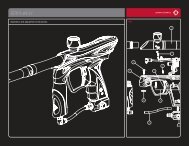
BODY KIT DISASSEMBLY1. Once you have removed the solenoid and the body from the SP-8 upper receiver, you are now leftwith the shell of the SP-8. The only time you will need to separate the two halves of the receiveris when you purchase a color body kit or need to replace a damaged part.2. To separate the two halves, first remove the upper receiver tactical rail by unscrewing the twoscrews and pulling straight upwards to remove. Also, you will need to remove the Round Activatorby pulling it in the same direction that the barrel points (Upper Reciever diagram).3. With the tactical rail and round activator removed, all that is left is to remove are the two upperreceiver screws. Once the two upper receiver screws have been removed, the two halves shouldcome apart. Make sure you pull the two halves apart gently. Do not force the partsUPPER RECEIVER DIAGRAM
BODY KIT DISASSEMBLY (CONT'D)4. Once the two halves have been separated, you should be able to easily remove the upper handle.The only pieces left that can be removed are the two metal clips and the feed neck.5. The metal clips are very easy to remove. Just slide them out and be careful not to drop or losethem. Be sure that when you replace the metal clips that the bent out “teeth” are facing up orfacing towards the top of the body where the tactical rail sits.6. The feed neck is a tight fit, so to remove it we suggest you use your loader elbow for extra grip.Screw on your elbow and twist the feed neck 180 degrees. Once the feed neck has been turned180 degrees it can then be pushed thru the body shell for removal. You will have to remove yourloader elbow from feed neck to push it thru the body shell all the way. (see feed tube diagram)FEED TUBE DIAGRAM
CLEANING/REASSEMBLY1. Cleaning the SP-8 is a simple process. Use a soft damp cloth to wipe down the parts, both internaland external. Wipe off old grease, dirt, debris, and broken paint. Pay special attention to theVision eye board. Make sure the eyes are very clean and are not bent or damaged.2. To properly lubricate the SP-8, grease the rearmost two o-rings located on the SP-8’s bolt. Use aliberal amount, but do not over grease or “glob” it on. Also grease both o-rings on the bolt stop.3. Place the bolt stop into the rear body half, and make sure that the concave side faces the backof the marker. Push the bolt stop in evenly, until it stops. Insert the bolt into the bolt stop/rearbody. Screw the front half of the body into the rear half. Set the Vision eye board into its slot withthe wire receptacle facing the rear of the body. Make sure the Vision eye board is seated all theway into the body.4. Inspect and thoroughly clean the area on the inner body where the Vision Eye sits with a cottonswab. Slide the metal body into the composite outer shell.5. Replace the rear banjo fitting with the shortest hose into the body first. NOTE: DO NOT OVER-TIGHTEN. Be sure to set the solenoid head into the groove to align the circuit board and otherhoses properly.6. Install the next longest hose and banjo into front fitting. NOTE: DO NOT OVERTIGHTEN.Replace the Vision eye harness into its receptacle. The Vision eye wire harness is meant to go inonly one way. Look carefully at the plug on the wiring and the socket on the eye board. The prongsin the socket are set to one side, not centered, as are the channels in the plug. Be certain to lineup the plug and socket properly when installing. Improper installation will cause damage to thesocket, causing failure of the Vision eye. (see figure 4)FIG. 47. Carefully feed the battery wires into the grip frame until the circuit board reaches the top of thegrip frame. Feed the circuit board into the board channel in the grip frame.8. When the board is almost all the way in the grip frame, push the longest hose and banjo into itschannel in the grip frame. Install the banjo fitting in the grip frame and tighten. Make sure allhoses and wires are inside the grip frame to prevent pinching or cutting of the wires. Gently pushthe circuit board down the channel, making sure to not bind or pinch the battery wires. Positionthe body onto the grip frame.9. Install both grip frame screws and tightenall with your 1/8" Allen wrench. NOTE: USE LONGERSCREW IN THE BACK OF THE FRAME, THE SHORTER SCREW IN THE FRONT. Attach batteryand wrap wire around the top of the battery. Set into grip frame and reinstall grip screws.
SOLENOID DISASSEMBLY/MAINTENANCE1. For solenoid disassembly, use your 3/32" Allen wrench to pry the bracket from the back of thesolenoid. BE SURE TO PLACE THE WRENCH BETWEEN THE BRACKET AND THE UPPERBLACK SECTION OF THE SOLENOID COIL. DO NOT PRY THE BRACKET AWAY ANYWHERENEAR THE RED WIRED SECTION. This will cause solenoid damage. After the bracket has beenremoved, pull the solenoid head straight up. Now tip the solenoid body over to remove thearmature. The armature comes out with extreme ease, so be careful not to lose it.2. Clean the inside of the solenoid with a cotton swab making sure to remove all grease and debris.Wipe off the armature as well. Reassemble the solenoid by replacing the armature into thesolenoid body making sure that the end with the large rubber bumper goes in first. Replace thesolenoid head by simply pushing it in to the solenoid body. Make sure that the long hoses andVision eye strip are running over the trigger switch for proper orientation. Replace the bracket bypushing it onto the solenoid above and below the red wired section. Make certain that the bentsection of the bracket goes onto the bottom side of the solenoid.NOTE: SHOULD YOU EVER NEED TO REMOVE THE HOSES FROM THE SOLENOID BARBFITTINGS, IT IS RECOMMENDED THAT YOU REMOVE THE SOLENOID HEAD FROM THESOLENOID/CIRCUIT BOARD, THEN REMOVE THE HOSES BY HOLDING THE BARB FITTINGWITH A BOX END OR SMALL CRESCENT WRENCH ON THE WRENCH FLATS FIRMLY WHILESTEADILY PULLING THE HOSE FREE. THIS PREVENTS STRESS ON THE SOLENOIDCOMPONENTS, AS WELL AS THE CIRCUIT BOARD. DO THE SAME WHEN INSTALLING NEWHOSES. ALSO APPLY A VERY SMALL AMOUNT OF LUBE TO THE FLARED BARB AREA OF THEFITTING TO EASE HOSE INSTALLATION.SOLENOID DIAGRAM
VELOCITY ADJUSTMENTRemove the clip by depressing the clip leverand pulling it away from the grip frame. Toadjust SP-8 velocity up or down, use the 5/8"side of the provided wrench to turn the hex sectionlocated at the bottom of the regulator—clockwise to turn velocity up, counter-clockwiseto turn velocity down. (see figure 5) Makeonly small adjustments at a time, shooting 5 to10 shots between adjustments to allow the regulatorto achieve the new pressure. Alwayschronograph your SP-8 between adjustments.CAUTIONE: NEVER ALLOW YOUR SP-8’SVELOCITY TO EXCEED 300FPS AT ANY TIME.FIG. 5REGULATOR DIAGRAM
REGULATOR DISASSEMBLY/MAINTENANCENOTE: ALL THREADS IN THE SP-8 REGULATOR ARE REVERSE THREADED. THIS MEANS THATTURNING THE INTERNAL PARTS CLOCKWISE LOOSENS, RATHER THAN TIGHTENS THE PARTS.TURNING PARTS COUNTER-CLOCKWISE TIGHTENS THE PARTS.1. Make sure the SP-8 is completely degassed.2. Remove the clip by depressing the clip lever and pulling it away from the grip frame.3. Remove the regulator from the SP-8 by unthreading it counter-clockwise from the marker assembly.The vertical disc filter will come free as well when you do this. Check the filter fordamage or debris, then set aside.4. Using the provided 3/32" Allen Wrench, remove both set screws on the regulator body. One screwis located on the outside of the regulator body, about halfway up. The other is located inside anoval shaped hole near the bottom of the body. To remove this screw, you may have to turn thevelocity adjuster with the provided 5/8" wrench to get the screw lined up in the oval slot.5. Using the 5/8" end of the provided wrench, completely remove the velocity adjuster by turningthe adjuster clockwise until free from the regulator body. Set aside.6. Using a 9/16" deep well socket, turn the internal brass hex socket clockwise (right) until it comesfree. As the brass hex piece comes free, so will the regulator spring.7. Using the provided 1/8" Allen Wrench, push the piston/regulator seat from the top of theregulator body out through the bottom until free.Thoroughly clean all the regulator parts by simply wiping clean with a paper towel or soft cloth.Lubricate both o-rings on the piston assembly. DO NOT LUBRICATE THE REGULATOR SEAT locatedat the end of the piston section OR the large o-ring located around the velocity adjuster.REGULATOR REASSEMBLY1. Push the piston/regulator seat, large end first, into the regulator body until it stops.2. Slip the regulator spring over the end of the piston inside the regulator body.3. Reinsert the brass hex piece and secure by turning the 9/16" deep well socket counter-clockwiseuntil snug. If you have installed this correctly, the brass will be visible through the set screw holein the regulator body.4. Replace the velocity adjuster by threading in counter-clockwise the lower set screw hole appearsin the oval slot on the regulator body.5. Replace both set screws into the regulator body until snug. Use a very small amount of blue(#242) Loctite or clear nail polish on the set screw threads in the velocity adjuster (inside theoval slot) during reassembly. DO NOT OVER TIGHTEN. Now slowly turn the adjuster all the wayin counter-clockwise (left) until it stops. This will ensure that that the regulator is supplying nopressure into the marker.6. Slip rubber outer grip over the top of the regulator body until it stops.7. Gas up the SP-8, then turn the pressure up by using the included 5/8" wrench and slowly turningthe velocity adjuster up (clockwise) until you reach 180psi. Be sure to cycle the SP-8 five toten shots between adjustments.
CIRCUIT BOARD SETTINGS/ADJUSTMENTThe SP-8 is programmed through the on/off switch and a similar switch located AT THE BOTTOMof the circuit board (see figure 6). This switch is rectangular, flat, gray, and sits directly behind thetrigger switch.To enter the programming mode and cycle through each programming setting:Turn the SP-8 on, then press the gray circuit board button once. The LED light will turn solid yellow.You are now at setting 1.To cycle through settings 2-6:Continue pressing the gray circuit board button. The LED lights will alternate between yellow and red,with alternating blinking patterns. The chart (below) explains the various modes and what they control.Changing circuit board settings:A) To alter any setting, use the gray circuit FIG. 6board button to select the setting.B) To make changes to a particular setting,press the on/off button. (Both LEDs willblink as adjustments are made.)C) When only the red LED is flashing, you havereached the end of the adjustment range.D) The UK board (green on/off light) is notcapable of full auto or 3-shot burst modes.CIRCUIT BOARD SETTINGSSetting Light Indication Mode FunctionONEDwell Up (solid yellow)TWODwell Down (solid red)THREERate of Fire Down (single blink yellow)FOURRate of Fire Up (single blink red)FIVECycle Modes Up (double blink yellow)SIXCycle Modes Down (double blink red)CYCLE MODES (from bottom)0. Semi1. Rebound2. 3-shot burst3. Full autoNOTE: UK markers (green on/off) do not have full auto or 3-shot modes.
TRIGGER ADJUSTMENTCAUTION: EXTREME TRIGGER ADJUSTMENTS (IN EITHER SCREW) CAN CAUSE THE SP-8 TONOT FIRE AND/OR DAMAGE THE TRIGGER SWITCH. MAKE CHANGES GRADUALLY AND MODER-ATELY.The SP-8 is equipped with an adjustable trigger. The length of the trigger stroke, tension and thetrigger stop point can all be adjusted through two set screws.1. Located near the bottom of the trigger, this screw is adjusted with the provided .050" Allenwrench. Turning the screw in stops the trigger sooner after the trigger fires the SP-8. Turning itout stops it later in the trigger cycle, making the trigger “sloppier”. (see figure 7)2. The other adjustment is the magnetic tension/pre-travel screw. It is located behind the triggerguard, just above the rubber grip. This screw shortens or lengthens the distance the trigger travelsbefore the trigger switch is activated, as well as the magnetic tension of the trigger. Theeasiest way to adjust this screw is to remove the left sidegrip screws (side with gauge) and foldthe grip behind the trigger guard. Turning the screw in brings the trigger closer to the triggerFIG. 7 FIG. 8
SP-8 PARTS LIST: A
SP-8 PARTS LIST: B
TROUBLESHOOTINGTHE SP-8 IS LEAKING.A) INTERNALLY:— The pneumatic hoses are loose, damaged or not fully connected.Replace hoses with Smart PartsSP-8 hoses only.— One or more of the pneumatic banjo fittings is loose or damaged. Tighten banjo fitting(s) orreplace with Smart Parts SP-8 banjo fittings only.— The solenoid armature is damaged or over pressurized. Replace armature and/or turn down operatingpressure to less than 200psi.— The SP-8 is leaking down the barrel. One or more of the bolt o-rings and/or the bolt stop o-ringsare damaged. Replace immediately.B) EXTERNALLY:— The macro line air fittings are venting or leaking air. Degas the SP-8, push the macro line hoseall the way into the fitting, then pull the hose back in the fitting, being certain that it catchesand seals. If this does not work, replace the macro line hose with a new piece.— Air is leaking from in and/or around the regulator. The bottle o-ring at the regulator top isdamaged. Replace it.— The regulator seat is contaminated and/or damaged. Replace with Smart Parts regulator seat only.(The regulator seat can be turned over and reused once.)THE SP-8 IS INCONSISTENT OR SHOOTS DOWN.— The barrel bore size is wrong for your paint. Adjust bore size or choose better quality paintballs.— The SP-8’s air source is low. Fill up your tank and make sure your tank is all the way on.— The SP-8’s battery is low. Replace with a high quality 9 volt battery.— The regulator seat is contaminated or damaged. Replace with Smart Parts regulator seat only.— The SFT o-ring, located inside the metal inner body, in front of the ball detents, is damaged,swollen, or missing. Replace with Smart Parts 17/90 o-ring only.— Liquid CO 2 is entering the regulator. Install an anti-siphon tube or use compressed air.THE SP-8 TURNS ON, BUT WILL NOT FIRE.— The battery is low or dead. Replace immediately.— The solenoid is clogged. Disassemble solenoid, clean armature and inside the solenoid body, thenreassemble WITHOUT lubrication.— One or more of the trigger set screws are adjusted too far in, putting pressure on the triggerswitch. Back screws out until trigger will activate the marker.— The trigger switch is damaged. Call Smart Parts or your local pro-shop for circuit board repair orreplacement.— Regulator pressure is too high (above 300 psi). Lower pressure and/or replace regulator seat.— Liquid CO 2 is entering the regulator. Install an anti-siphon tube or use compressed air.THE SP-8 BREAKS PAINT.— The SP-8’s battery is low. Replace with a high quality 9 volt battery.— The ball detents are worn. Replace with SP-8 ball detents only.— The barrel bore size is wrong for your paint. Adjust bore size or choose better quality paintballs.— The dwell of the SP-8 is too high. Lower in 3 click increments. Retest in between adjustments.— The eyes are off. Place SP-8 into Vision mode.— The eyes are covered with paint, allowing the SP-8 to shoot without paintballs, even in Visionmode. Clean Vision eyes, as well as the slot they sit in, then reinstall.— The eyes are damaged or covered with paint or debris. Clean or replace the eye board.— The eye board wiring harness is damaged from improper installation. Replace.— Liquid CO2 is entering the regulator. Install an anti-siphon tube or use compressed air.
WARNING: LIQUID CO 2 COULD DAMAGE YOUR SP-8THE BIGGEST ENEMY OF THE SP-8 AND ANY PAINTBALL MARKER, IS LIQUID CO 2 .Gas state CO 2 is the preferred type of CO 2 used to power paintball markers. Liquid CO 2 is the moredense and liquefied version of the gas CO 2 used to power markers. Liquid CO 2 can, and will damageseals in the SP-8 as well as a massive chilling in certain temperatures, causing failure of the marker.Liquid CO 2 is found, at least a little, in every filled CO 2 tank. The cooler and more humid it gets,as well as how fast you shoot continuously, the more liquid CO 2 will form from the gas CO 2 in your tankcausing shoot down, freezing, massive velocity spikes, and seal damage.In the SP-8, the biggest thing to look for is liquid CO 2 flowing into the regulator, causing it to riseabove 200psi. The safest thing to do is to shut the air off and allow the SP-8 to warm up. This shouldbe easy with any on/off valve. Simply shut the valve off, and if possible shoot out the excess pressure.DO NOT REMOVE THE TANK FROM THE MARKER UNLESS ABSOLUTELYNECESSARY IN THIS SITUATION. If liquid CO 2 is a persistent problem, you should have ananti-siphon tube, as well as an on/off valve, installed by Smart Parts or your local dealer. If you areuncertain as to what you should do, ask a qualified person as soon as possible.DO NOT ATTEMPT TO WORK ON A PRESSURIZED MARKER IF YOU DO NOT KNOW WHAT YOUARE DOING.WARRANTYSmart Parts warrants for one (1) year to initial retail purchaser that the paintball marker and regulator are free from defects in materialsand workmanship. Disposable parts (batteries, o-rings, seals, etc.) are not warranted. The valve assembly is warranted for six (6) months. Thesolenoid and electronics on the marker are warranted for six (6) months, plus an additional warranty of six months for electronic parts only (installationand labor are not included.) This warranty does not cover surface damages (scratches and nicks), misuse, improper disassembly andre-assembly, attempts made to drill holes or remove metal from the external surfaces which could degrade performance and reduce pressuresafety factors of the marker. Do not make changes to the basic marker parts without written approval. The only authorized lubricant for the markeris DOW 33 Lubricant. Use of any other lubricant could result in voiding your warranty. <strong>Paintball</strong> markers are non-refundable. This warranty islimited to repair or replacement of defective parts with the customer to pay shipping costs. This warranty is effective only if the customer returnsthe warranty registration card enclosed with the marker. The warranty is non-transferrable. Do not attempt to alter the trigger assembly in anyway, as this will void your Smart Parts Inc. warranty. Trigger alteration of any kind may result in serious injury.TECH SUPPORTSmart Parts, Inc.100 Station StreetLoyalhanna, PA 15661Hours (EST)M-F 10-6800-992-2147smartparts.comWest Coast Repair Center27326 Jefferson Ave #12Temecula, CA 92590Hours (PST)7 Days 11-6800-992-2147smartparts.comEuropean Repair CenterUnit 3 Old Bexley Business Park19 Bourne Road, Bexley, KentDA5 1LR EnglandHoursM-F 9-6, Saturday 10-4++44 (0)1322 555968smartpartseurope.co.ukThe SP-8 marker and accessories are covered by the following patents: [MARKER] 6,474,326 B1; 6,035,843; 5,881,707; 5,967,133 [REG-ULATOR] 5,755,213; 5,957,119 [BARREL] 5,228,427 Additional U.S. and Foreign patents pending. Made in the United States of America.
P.O. BOX 3200 | LATROBE, PA 15650 | 800.992.2147 | SMARTPARTS.COM