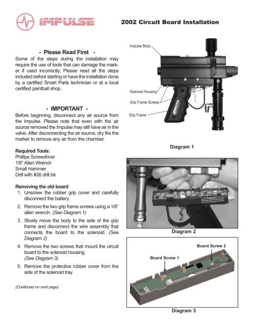
2002 Circuit Board Installation - Claymore Paintball
2002 Circuit Board Installation - Claymore Paintball
2002 Circuit Board Installation - Claymore Paintball

Create successful ePaper yourself
Turn your PDF publications into a flip-book with our unique Google optimized e-Paper software.
<strong>2002</strong> <strong>Circuit</strong> <strong>Board</strong> <strong>Installation</strong><br />
- Please Read First -<br />
Some of the steps during the installation may<br />
require the use of tools that can damage the marker<br />
if used incorrectly. Please read all the steps<br />
included before starting or have the installation done<br />
by a certified Smart Parts technician or at a local<br />
certified paintball shop.<br />
- IMPORTANT -<br />
Before beginning, disconnect any air source from<br />
the Impulse. Please note that even with the air<br />
source removed the Impulse may still have air in the<br />
valve. After disconnecting the air source, dry fire the<br />
marker to remove any air from the chamber.<br />
Required Tools:<br />
Phillips Screwdriver<br />
1/8” Allen Wrench<br />
Small Hammer<br />
Drill with #26 drill bit<br />
Impulse Body<br />
Solenoid Housing<br />
Grip Frame Screws<br />
Grip Frame<br />
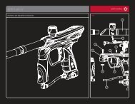
Diagram 1<br />
Removing the old board<br />
1. Unscrew the rubber grip cover and carefully<br />
disconnect the battery.<br />
2. Remove the two grip frame screws using a 1/8”<br />
allen wrench. (See Diagram 1)<br />
3. Slowly move the body to the side of the grip<br />
frame and disconnect the wire assembly that<br />
connects the board to the solenoid. (See<br />
Diagram 2)<br />
4. Remove the two screws that mount the circuit<br />
board to the solenoid housing.<br />
(See Diagram 3)<br />
5. Remove the protective rubber cover from the<br />
side of the solenoid tray.<br />
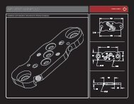
<strong>Board</strong> Screw 1<br />
Diagram 2<br />
<strong>Board</strong> Screw 2<br />
(Continued on next page)<br />
Diagram 3
Installing the new board<br />
1. Using a #26 drill bit, check the diameter of the of the top right hole on the back of the solenoid housing. If<br />
the #26 bit does not easily pass through the hole, it will required to drill the hole using the #26 bit.<br />
1. Using a small hammer, or pressing against a hard flat surface, press the power button into the hole on the<br />
back of the solenoid housing until the ridge on the button is inside the solenoid housing. (See Diagram 4)<br />
2. Using a small hammer, or pressing against a hard flat surface, press the button housings into each of the<br />
two slots on the side of the solenoid housing. (See Diagram 4)<br />
3. Slide the two slot covers into the two remaining slots on the side of the solenoid housing. (See Diagram 4)<br />
4. Insert one dwell button cap into each of the button housings on the side of the solenoid housing, with the<br />
indented side facing toward the blue button. (See Diagram 4)<br />
5. Rest the new circuit board on top of the solenoid housing and push the 9-volt battery connector down into<br />
the grip frame.<br />
6. Slide the circuit board in at a slight angle to correctly align the blue buttons with the button caps on the side<br />
of the solenoid housing and the power button on the back.<br />
7. Insert and tighten the two circuit board screws, making sure that the circuit board is correctly positioned<br />
over the mounting holes on the solenoid housing.<br />
8. For Vision Eye boards, mount the upper board to the bottom of the Impulse body, using the two plastic<br />
screws provided. Turn screws in until snug and then unscrew 1/4 turn to allow adjustment for upper and<br />
lower board fit when assembling the body and solenoid housing.<br />
(See Diagram A)<br />
Upper <strong>Board</strong> Assembly<br />
9. Attach the solenoid wiring assembly to the circuit board.<br />
10. Assemble the grip frame, solenoid housing and body using the two frame<br />
screws. Note: The lower part of the Vision Eye cover must be fitted into the<br />
slot on the solenoid housing before tightening the frame screws.<br />
11. Attach the Vision flex circuit to the body using the small set screw.<br />
(See Diagram A)<br />
12. Attach the eye ball detent through the Vision Eye cover to the Impulse body.<br />
13. Attach a 9-volt battery to the power supply.<br />
14. Attach the air supply and follow the instructions for firing and adjusting your<br />
new Impulse Vision Eye.<br />
Diagram A<br />
885<br />
885<br />
893<br />
897<br />
883<br />
Power Button (883)<br />
Button Housing (885)<br />
898<br />
893<br />
Dwell Button Cap (893)<br />
Slot Cover (897)<br />
Slot Cover (898)<br />
Solenoid Tray<br />
Diagram 4<br />
United States<br />
100 Station Street<br />
Loyalhanna, PA 15661<br />
(724) 539-2660<br />
www.smartparts.com<br />
Europe<br />
Unit 3<br />
Old Bexley Bus. Park<br />
19 Bourne Road<br />
Bexley, Kent DA5 1LR<br />
(44) 1322-555-968