AIR VENT MANIFOLD - Claymore Paintball
AIR VENT MANIFOLD - Claymore Paintball
AIR VENT MANIFOLD - Claymore Paintball
- No tags were found...

You also want an ePaper? Increase the reach of your titles
YUMPU automatically turns print PDFs into web optimized ePapers that Google loves.
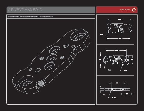
<strong>AIR</strong> <strong>VENT</strong> <strong>MANIFOLD</strong>Installation and Operation Instructions for Shocker Accessory
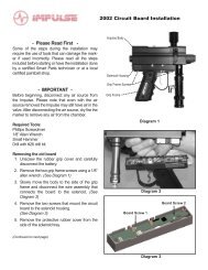
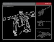
INSTALLATION INSTRUCTIONS[ PLEASE READ CAREFULLY ]01 02 03 040506Remove the grip framefrom the Shockerbody. (Refer to thedisassembly section inyour Shocker owner’smanual–an additionalhex wrench will berequired.)Take a good look atthe solenoid valve, andthe manifold plate onwhich it is mounted.The Air Vent Manifoldwill be installed in thesame position as theoriginal manifold plate.If your Shocker SFT isequipped with a VisionEye, carefully unplugthe Vision flex stripfrom the upper circuitboard (the circuit boardmounted on the solenoidvalve.)Unscrew both solenoidmounting screws usinga 1/16” Allen Wrench,and gently pull the solenoidvalve away fromthe body.Note the positions ofthe three round o-ringsin the stock manifoldplate. Insert the newo-rings in their correspondingpositions onthe Air Vent Manifold.Using the 1/16” AllenWrench, remove bothscrews that are holdingthe old manifold plateto the Shocker body.070809 10 11Note the positions ofthe one round and thetwo oblong o-ringsin the stock manifoldplate. Insert the newo-rings in their correspondingpositions onthe Air Vent Manifold.Save the old o-rings asspares.Install the new manifoldplate. The oval shaped o-ring grooves will face theShocker body. Make surethat the rounded side ofthe plate points towardsthe barrel end of themarker. Use firm pressure,but do not over-tightenthe manifold plate screws.Replace solenoid and screws using the 1/16” Allenwrench. Use only a gentle tightness on these screws.DO NOT OVERTIGHTEN THE SCREWS OR YOUWILL STRIP THE <strong>MANIFOLD</strong> PLATE.Reattach the Vision flexstrip with the metal contactsfacing away fromthe Shocker SFT body.Reassemble yourShocker.Be careful not tooverstress the solenoidmounting screws whenaligning the body andgrip frame, or to pinchthe wiring harnessinside the grip frame.800.922.2147 www.smartparts.com02
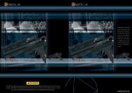
ADJUSTMENT THEORYThe adjusters work byrestricting gas flow.When you are making adjustments, screwing the forward screw in clockwise will softenthe force used to close the bolt, allowing the Shocker to be more gentle on paint. If you areexperiencing paint breakage in the breech or back of the barrel or simply want to reducerecoil, turn this adjuster screw in further for softer closing force. Screwing the rear screw inclockwise will soften the force applied to open the bolt after each shot.Significant reduction of the forward air flow may require a corresponding increase in theShocker’s Dwell setting (see Shocker manual) to maintain proper velocity. Most players willwant to adjust both directions about the same amount, so the recoil has an even feel–justas strong forward as back–however, the Air Vent Manifold gives you the ability to tune towhat you like best. As you adjust, remember that softening the pressure is slowing boltmovement, which will ultimately reduce your maximum rate of fire–so only restrict the gasflow as much as is needed to achieve the feel you want.Thread locking compound is applied to the adjustment screws at the factory. If, after multipleadjustments the screws turn freely, you may wish to relock your final setting with a tinydrop of blue Locktite 242 or equivelant thread locking compound applied to the edge ofthe screw.FIG. 04FIG. 05Turn Clockwise to Decrease FlowTurn Counterclockwise to Increase Flow.800.922.2147 www.smartparts.com03
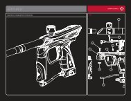
ADJUSTMENT METHODSChanging the setting of either adjustmentscrew does not require complete disassemblyof the Shocker SFT. Follow these steps tomake an adjustment.With both adjustment screws backed out all the way, the Shocker SFT will operateas with the stock plate. Turning the screws in (clockwise) will restrict gas flow.01 02 03 04 0506Remove the hopper andpaint, and de-gas themarker as you did duringinstallation.Loosen the grip framescrews enough to separatethe Shocker SFTbody and grip frame onlyfar enough to exposethe Air Vent Manifold(approximately three fullturns)Be very careful to supportboth the body andgrip frame so that theydo not flex and strain thesolenoid mount screws.Using the 0.035 inch AllenWrench, adjust one orboth of the Air Vent Manifoldadjustment screws.Forward bolt movementis adjusted from the rightside of the Shocker SFT[ FIG. 06 ] , rear boltmovement is adjustedfrom the left side of theShocker [ FIG. 07 ]Close the grip frameand body back together,and tighten thegrip frame screws.Take care not to pinchthe wiring harnessinside the grip frame.If necessary, removethe Shocker SFT’sgrips and guide thewiring harness frombelow.Utilizing proper paintballsafety procedures(goggles designed forpaintball, a safe area,etc.) test fire the ShockerSFT, and decide ifyou should make furtheradjustments.Repeat from step 1 untilyou are pleased with yournewly custom tunedShocker SFT. When youhave achieved your finaladjustments, you maywish to use the tip of the0.035 inch Allen Wrenchto apply a tiny amount oftemporary thread lockingcompound (Blue Loctite242 or equivalent) tothe edge of the adjusterscrews if the factory appliedthread locker hasworn away.FIG. 06 FORWARD FLOW ADJUSTMENTFIG. 07REAR FLOW ADJUSTMENT800.922.2147 www.smartparts.com04