

Folsom Lake Crossing - Aspire - The Concrete Bridge Magazine
Folsom Lake Crossing - Aspire - The Concrete Bridge Magazine
Folsom Lake Crossing - Aspire - The Concrete Bridge Magazine

You also want an ePaper? Increase the reach of your titles
YUMPU automatically turns print PDFs into web optimized ePapers that Google loves.
Design and Construction –<br />
<strong>Folsom</strong> <strong>Lake</strong> <strong>Crossing</strong><br />
by Hans Strandgaard, Alex Harrison, Jeff Aldrich, and Jeff Thomure, CH2M HILL<br />
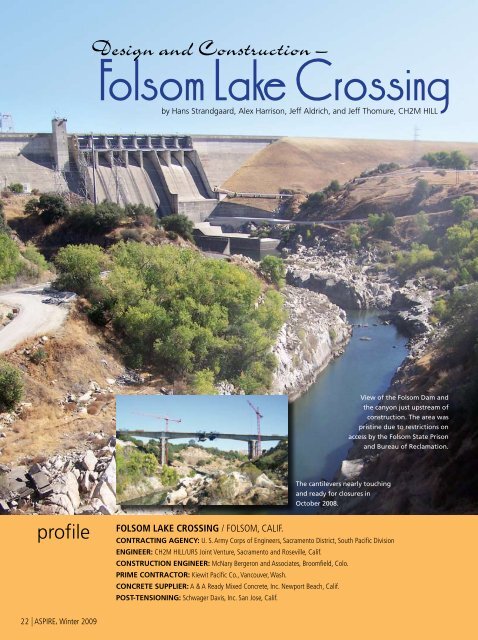
View of the <strong>Folsom</strong> Dam and<br />
the canyon just upstream of<br />
construction. <strong>The</strong> area was<br />
pristine due to restrictions on<br />
access by the <strong>Folsom</strong> State Prison<br />
and Bureau of Reclamation.<br />
<strong>The</strong> cantilevers nearly touching<br />
and ready for closures in<br />
October 2008.<br />
profile<br />
FOLSOM LAKE CROSSING / FOLSOM, CALIF.<br />
Contracting Agency: U. S. Army Corps of Engineers, Sacramento District, South Pacific Division<br />
Engineer: CH2M HILL/URS Joint Venture, Sacramento and Roseville, Calif.<br />
Construction Engineer: McNary Bergeron and Associates, Broomfield, Colo.<br />
Prime Contractor: Kiewit Pacific Co., Vancouver, Wash.<br />
<strong>Concrete</strong> Supplier: A & A Ready Mixed <strong>Concrete</strong>, Inc. Newport Beach, Calif.<br />
Post-Tensioning: Schwager Davis, Inc. San Jose, Calif.<br />
22 | ASPIRE, Winter 2009
<strong>Folsom</strong> Dam Road, located on the crest<br />
of <strong>Folsom</strong> Dam, near the city of <strong>Folsom</strong>,<br />
Calif., was operational from the time<br />
of the dam’s construction in 1956,<br />
until it was closed to public traffic in<br />
2002, as a result of national security<br />
concerns. <strong>The</strong> road was an important<br />
regional transportation artery, with<br />
18,000 vehicles using it daily as a link<br />
between Sacramento, El Dorado, and<br />
Placer counties. Following the 2002 road<br />
closure, traffic across the American River<br />
was detoured to other downstream<br />
bridges, often resulting in gridlock<br />
within the city of <strong>Folsom</strong>. In response<br />
to local congestion concerns, plans for a<br />
new crossing of the American River near<br />
<strong>Folsom</strong> Dam were fast-tracked by local<br />
and state officials. When federal funding<br />
for a new crossing was appropriated<br />
in 2006, along with additional funding<br />
from the city of <strong>Folsom</strong> and the State<br />
of California, the project had adequate<br />
resources to begin at once.<br />
In response to the community’s desire<br />
to open the new crossing to traffic<br />
as quickly as possible, the U.S. Army<br />
Corps of Engineers (USACE) and the<br />
project development team adopted<br />
an aggressive design and delivery<br />
schedule that included preparing the<br />
environmental documentation in parallel<br />
with the engineering studies, design,<br />
and right-of-way acquisition for the new<br />
roadway and bridge.<br />
<strong>The</strong> USACE selected the CH2M HILL/<br />
URS joint venture to prepare designs<br />
for the bridge and approach roadways.<br />
As the bridge designer, the CH2M HILL<br />
project team’s mission was to produce a<br />
design to be constructed on a fast-track<br />
schedule, within a limited budget, while<br />
maintaining the required level of quality,<br />
constructability, and acceptance from a<br />
broad range of stakeholders.<br />
Kiewit made dual use of the struts to act as falsework for the pier table and then<br />
to strut the pier tables to reduce rotation and construction stresses as the cantilevers<br />
were constructed.<br />
Site Features and<br />
Constraints<br />
<strong>The</strong> selected river crossing site, approximately<br />
1 /2-mile downstream of the<br />
dam, presented multiple challenges for<br />
the bridge design and construction.<br />
Limitations on the maximum roadway<br />
profile grade resulted in the vertical<br />
alignment that crossed the canyon<br />
approximately 200 ft above the river.<br />
Existing access into the steep inner<br />
canyon was very limited. In addition, the<br />
California Department of Corrections<br />
and Rehabilitation (CDCR) expressed<br />
security concerns related to increasing<br />
site accessibility next to <strong>Folsom</strong> State<br />
Prison—a high-security facility—located<br />
adjacent to the alignment.<br />
Project Coordination<br />
Challenges<br />
<strong>The</strong> tight project schedule and the<br />
simultaneous development of the design<br />
and the environmental document were<br />
identified as being major constraints<br />
to the design team; however, weekly<br />
meetings and continuous exchange<br />
of information expedited project<br />
coordination and delivery.<br />
Key concerns among the various<br />
stakeholders involved security issues, as<br />
well as maintenance of dam operations<br />
during and after construction of the<br />
new bridge and roadway. Property<br />
acquisition was required from the CDCR,<br />
the California Department of Parks<br />
and Recreation, and the U.S. Bureau of<br />
Reclamation, as well as from private land<br />
owners. While other alignments may<br />
have resulted in a more favorable bridge<br />
layout, it could not accommodate the<br />
required schedule. In addition, relocating<br />
the existing <strong>Folsom</strong> Dam powerhouse<br />
access road was unacceptable, as it<br />
would potentially disrupt the only access<br />
to this critical facility.<br />
A cast-in-place concrete segmental box girder<br />
was the most appropriate structure type.<br />
Cast-in-Place Segmental Box Girder <strong>Bridge</strong> / CITY OF FOLSOM, Owner<br />
Spherical Bearings: Lubron Bearing Systems, Huntington Beach, Calif.<br />
Rock Anchor Holes: Drilltech Systems Drilling and Shoring Inc., Antioch, Calif.<br />
BRIDGE DESCRIPTION: Three-span, cast-in-place, segmental box girder, 970 ft long with 430-ft main span and 270-ft approach spans<br />
<strong>Bridge</strong> Cost: $38,378,000 (as bid)<br />
Project Cost: $73,294,000 (as bid)<br />
ASPIRE, Winter 2009 | 23
<strong>Bridge</strong> Type Selection<br />
<strong>The</strong> bridge type selection study<br />
conducted during the preliminary design<br />
phase investigated a range of bridge<br />
types and span arrangements, as well as<br />
alternative bridge construction materials.<br />
It was determined that a minimum main<br />
span length of approximately 350 to<br />
400 ft was required to span the inner<br />
portion of the canyon and keep the pier<br />
foundations above the flood elevation.<br />
<strong>The</strong> design team identified a cast-inplace<br />
concrete box girder as the most<br />
appropriate structure type for this<br />
crossing. Box girder bridges are the most<br />
widely constructed highway bridge type<br />
in California. Local contractors have a<br />
long record of successfully constructing<br />
this bridge type, and the design<br />
team understood that competitive<br />
bids could be obtained and potential<br />
schedule delays reduced as a result of<br />
the familiarity of the local construction<br />
market with this structure type. From the<br />
owner’s perspective, concrete box girder<br />
bridges have a solid record of long-term<br />
performance and low maintenance in<br />
the Sacramento environment. Further,<br />
the seismic behavior and design features<br />
of this structure type are relatively well<br />
defined in California.<br />
One project issue related to concrete box<br />
girder construction was the feasibility of<br />
using falsework for construction. While<br />
falsework has been used in California for<br />
construction of tall three- and four-level<br />
freeway interchanges, the 200-ft height<br />
above the river canyon posed significant<br />
problems. Further, the use of falsework<br />
required supports to be placed in the<br />
American River, which introduced a high<br />
level of risk in the event of flooding, and<br />
long-span steel truss falsework was cost<br />
prohibitive. <strong>The</strong> design team identified<br />
cast-in-place segmental construction<br />
as being the only practical method of<br />
box girder bridge construction for this<br />
site. Several alternative bridge structure<br />
types were considered including arch,<br />
extradosed, steel plate girder, and<br />
spliced precast concrete girder bridges.<br />
Following consultation with constructability<br />
resources and preparation of<br />
cost estimates for these alternatives,<br />
the design team recommended a castin-place<br />
concrete segmental box girder<br />
with integral piers.<br />
Span Arrangement and<br />
<strong>Bridge</strong> Layout<br />
<strong>The</strong> selected three-span bridge has a<br />
main span of 430 ft with equal side<br />
spans of 270 ft. Given site geology and<br />
topography, this span arrangement<br />
accommodates a feasible foundation<br />
configuration, and allowed construction<br />
to proceed in four simultaneous<br />
headings from two pier tables, which<br />
shortened the schedule. <strong>The</strong> symmetrical<br />
span arrangement simplified both design<br />
and construction details, and provided<br />
for maximum repetition. <strong>The</strong> overall<br />
bridge length was well suited to the site<br />
topography, which resulted in minimal<br />
abutment heights or fills.<br />
A variable-depth box girder was<br />
selected with a total depth that varied<br />
between 10 ft at midspan to 26 ft at<br />
the piers. Exterior webs were sloped<br />
to minimize the piers’ cross-sectional<br />
width, and to provide for improved<br />
aesthetics. <strong>The</strong> 82-ft-wide bridge deck<br />
will accommodate four traffic lanes<br />
with a 4-ft-wide median. In addition, a<br />
12-ft-wide regional trail located on the<br />
north side of the roadway will provide<br />
for an unprecedented and dramatic view<br />
of the dam.<br />
Superstructure Design<br />
<strong>The</strong> box girder cross section has two<br />
cells with a deck slab that spans<br />
approximately 28 ft between web<br />
centerlines and has 12-ft-long deck<br />
cantilevers. This arrangement optimizes<br />
the deck slab thickness while providing<br />
for an adequate cross section at the<br />
tops of the webs to locate cantilever<br />
post-tensioning ducts and anchorages.<br />
<strong>The</strong> deck slab is transversely posttensioned<br />
to minimize slab thickness<br />
and control cracking. <strong>The</strong> design team<br />
selected the segment arrangement to be<br />
within the capacity of available traveling<br />
forms while minimizing the number of<br />
segments to be cast on each cantilever.<br />
A segment length of 12 ft adjacent to<br />
the piers and 15.5 ft away from the<br />
piers was selected.<br />
Design of the <strong>Folsom</strong> <strong>Lake</strong> <strong>Crossing</strong><br />
utilized three-dimensional analytical<br />
modeling. While traditional practice for<br />
transverse design of segmental bridges<br />
has been to use an elastic plate analysis<br />
in conjunction with two-dimensional<br />
frame models, this approach has<br />
practical limitations on variable depth<br />
girders. Sections with shorter webs<br />
have a greater bending stiffness and<br />
develop larger live-load web moments<br />
than sections with deeper webs. While<br />
this effect can be accounted for in twodimensional<br />
models, development of<br />
a three-dimensional model allowed for<br />
more accurate determination of internal<br />
cross-section forces. In addition, the<br />
three-dimensional model was used to<br />
study shear lag effects over the length<br />
of the cantilevers.<br />
Kiewit lifted concrete from<br />
the pier bases in 4 yd 3 buckets<br />
to a remixer/pumper located<br />
at the top of the pier table.<br />
Segments were cast full depth<br />
in a single placement.
<strong>The</strong> cantilevers progressing in September 2008.<br />
Form traveler for cast-in-place<br />
segmental construction advancing<br />
from the pier table. Portions of the<br />
travelers were last used on the nearby<br />
Benicia-Martinez <strong>Bridge</strong> project.<br />
Substructure Design<br />
<strong>The</strong> pier configuration consisted of a<br />
“dogbone” cross section column<br />
extending from the spread footings to<br />
a transition element at the top of the<br />
column. This prismatic column cross<br />
section provided sufficient ductility<br />
under transverse seismic loadings, and<br />
allowed the use of repetitive details<br />
and maximum reuse of column forms.<br />
One aesthetic feature incorporated<br />
into the substructure design was a<br />
truncated pyramid transition element<br />
that provided for a smooth visual and<br />
structural transition from the columns to<br />
the superstructure soffit. Spread footings<br />
were used on top of the granite bed<br />
rock.<br />
Seismic Design<br />
Considerations<br />
Seismic design is a major consideration<br />
for any bridge built in California, and<br />
particularly for a long-span, relatively<br />
heavy concrete bridge with tall columns.<br />
With an estimated peak horizontal<br />
ground acceleration of 0.4 times gravity,<br />
the site is considered a moderate seismic<br />
zone. Finite element analysis was<br />
used to determine elastic acceleration<br />
response spectrum (ARS) analysis forces<br />
and structure displacements.<br />
<strong>The</strong> structure was designed in<br />
accordance with California Department<br />
of Transportation (Caltrans) design<br />
standards to manage the formation<br />
of plastic hinging in the piers in a<br />
completed configuration. <strong>The</strong>se plastic<br />
hinging forces are resisted by “joint”<br />
regions in the pier table and footing.<br />
<strong>The</strong>se are designed to remain essentially<br />
elastic, as are the superstructure and<br />
the footings. <strong>The</strong> pier table joint region<br />
required particular attention due to<br />
the steel required to sustain the joint<br />
forces in combination with the heavy<br />
reinforcement and tendon density<br />
driven by segmental construction.<br />
Caltrans’ design criteria were verified<br />
with complex cracked concrete threedimensional<br />
block finite element analysis<br />
to verify the design reinforcement<br />
configuration. Integrated drawings were<br />
developed for this region to eliminate<br />
potential interference and enhance<br />
detailing of the reinforcement. Similarly,<br />
the footings were designed to transfer<br />
the pier plastic moments through the<br />
footing and into the rock foundation<br />
using post-tensioned tie-downs.<br />
A horizontal construction seismic load<br />
of 10% of gravity was considered for<br />
the balanced cantilever construction<br />
configuration, prior to completion of closure<br />
pours and before the spans were connected.<br />
Both the pier and spread footings were<br />
evaluated in this analysis to ensure that there<br />
is not a collapse if a moderate earthquake<br />
occurs during construction.<br />
<strong>The</strong> bridge is expected to open in spring<br />
2009.<br />
____________<br />
Hans Strandgaard is senior technologist<br />
and regional quality manager, Alex<br />
Harrison is senior technologist and<br />
regional bridge practice lead, Jeff Aldrich<br />
is senior technologist, and Jeff Thomure<br />
is bridge engineer with CH2M HILL,<br />
Sacramento, Calif.<br />
For more information on this or other<br />
projects, visit www.aspirebridge.org.<br />
ASPIRE, Winter 2009 | 25
FOLSOM LAKE CROSSING / CALIFORNIA<br />
Kiewit constructed a liquid nitrogen plant to lower<br />
the initial temperatures of the concrete for mass<br />
Looking from the Pier 3 cantilever towards Pier 2, shows the height of the structure<br />
concrete placements.<br />
over the water and the reconstruction efforts required for the slope<br />
Web | ASPIRE, Winter 2009
FOLSOM LAKE CROSSING / CALIFORNIA<br />
Pier 3 in June 2008.<br />
<strong>The</strong> cantilevers starting<br />
in August 2008.<br />
ASPIRE, Winter 2009 | Web
FOLSOM LAKE CROSSING / CALIFORNIA<br />
Bar reinforcing at one of the<br />
pier tables was very dense<br />
due to seismic requirements.<br />
Web | ASPIRE, Winter 2009


