Introduction - sensitec
Introduction - sensitec
Introduction - sensitec

Create successful ePaper yourself
Turn your PDF publications into a flip-book with our unique Google optimized e-Paper software.
Installation and Operation<br />
4. Installation and Operation<br />
4.1 Connections / Display<br />
The control monitor CoMo Net must be used only under<br />
specified operating conditions (see section 7.8 ‘Technical<br />
data’). It must be protected against excessively dusty conditions<br />
as well as mechanical stress (shock, vibration). High<br />
levels of humidity, which can cause condensation in the<br />
event of temperature changes, must be avoided.<br />
Make sure to protect the inputs and outputs of the control<br />
monitor against contamination and do not touch insulation<br />
with your fingers. Fit the covers supplied over unused connectors.<br />
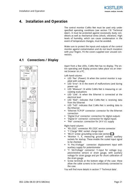
Apart from a few LEDs, CoMo Net has no display. The entire<br />
operating and display process takes place via an Internet<br />
browser on a PC.<br />
Left-hand column:<br />
• LED ‘Pwr’ (Power): lit when the control monitor is supplied<br />
with voltage<br />
• LED ‘Error’: lit in the event of malfunctions (and during<br />
power-up)<br />
• LED ‘Measure’: lit while CoMo Net is measuring or calculating<br />
evaluations<br />
• LED ‘Link’: lit when the Ethernet is connected at the<br />
electrical level<br />
• LED ‘RxD’: indicates that CoMo Net is receiving data<br />
from the Ethernet<br />
• LED ‘TxD’: indicates that CoMo Net is sending data to<br />
the Ethernet<br />
• ‘Ethernet TCP/IP’ connector: connector for the Ethernet<br />
connection<br />
• ‘Digital Out’ connector: connection for digital outputs<br />
• ‘Digital In’ connector: connection for digital inputs<br />
• ‘Pwr’ connector: connection for 24 V d.c supply<br />
Right-hand column:<br />
• ‘RS-232C’ connector: RS-232C service connector<br />
• ‘Y Charge’ BNC socket: charge input<br />
• ‘M2,5’ screw: grounding screw (see section 8.3)<br />
• ‘Monitor Y, X, measuring ground’ sockets: auxiliary<br />
sockets for startup. These enable the scaled input signal<br />
to be checked.<br />
• ‘X: Pot./Voltage’ connector: displacement input with<br />
auxiliary supply for potentiometer<br />
• ‘Y: SG/Voltage’ connector: Y-input for voltage (e.g.<br />
piezoresistive sensor) or strain gauge, with auxiliary<br />
voltage for strain gauge and pin for shunt calibration of<br />
the strain gauge<br />
• Screw terminals at the bottom edge of the case: these<br />
allow the cable screens to be conductively connected to<br />
the case.<br />
You will find more details in section 7 ‘Technical data’.<br />
002-228e-08.03 (B10.5863Ae) Page 21