Lawn Genie Richdel L80306p Controller Owner's ... - Irrigation Direct
Lawn Genie Richdel L80306p Controller Owner's ... - Irrigation Direct
Lawn Genie Richdel L80306p Controller Owner's ... - Irrigation Direct

You also want an ePaper? Increase the reach of your titles
YUMPU automatically turns print PDFs into web optimized ePapers that Google loves.
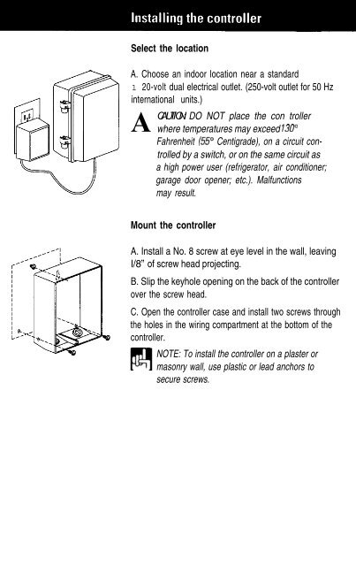
Select the location<br />
A. Choose an indoor location near a standard<br />
1 20-volt dual electrical outlet. (250-volt outlet for 50 Hz<br />
international units.)<br />
A<br />
CAUTION: DO NOT place the con troller<br />
where temperatures may exceed 130”<br />
Fahrenheit (55” Centigrade), on a circuit controlled<br />
by a switch, or on the same circuit as<br />
a high power user (refrigerator, air conditioner;<br />
garage door opener; etc.). Malfunctions<br />
may result.<br />
Mount the controller<br />
A. Install a No. 8 screw at eye level in the wall, leaving<br />
l/8” of screw head projecting.<br />
B. Slip the keyhole opening on the back of the controller<br />
over the screw head.<br />
C. Open the controller case and install two screws through<br />
the holes in the wiring compartment at the bottom of the<br />
controller.<br />
NOTE: To install the controller on a plaster or<br />
masonry wall, use plastic or lead anchors to<br />
secure screws.<br />
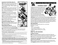
Wire the valves<br />
A. Run valve wiring underground wherever possible. For Wires to individual controller terminals<br />
line runs less than 800 feet long, use 18-gauge, plastic<br />
jacketed thermostat control wire; over 800 feet, use<br />
14-gauge wire. Your dealer can provide this wire in 2,3,<br />
4, 5,6,7 and 8-wire color-coded strands.<br />
B. Connect a single common wire to one of the wires<br />
from each valve. NOTE: It doesn’t matter which of the<br />
two valve wires you use.<br />
C. Solder or join all splices with wire nuts; then seal<br />
One wire from each valve connects<br />
with vinyl or waterproof cement to assure a water-<br />
to a single common wire running to<br />
controller<br />
resistant connection.<br />
IMPORTANT: The power transformer is protected<br />
by an electronic circuit breaker: Do not connect<br />
a combination of valves requiring an inrush current<br />
of more than 1 amp at 24 VAC.<br />
Connect the valve wires to controller<br />
A. Run all valve wires up through the insulated hole in<br />
bottom of controller.<br />
B. Connect the wire from valve number 1 to the terminal<br />
screw marked 1 on the controller; the wire from valve<br />
number 2, to the terminal 2, and so on. This allows your<br />
controller to selectively water the Zone controlled by<br />
( each valve.<br />
NOTE: On the L80306P terminal designations<br />
are marked on the inside of the wiring<br />
compartment cover.<br />
C. Connect the common wire to the terminal marked<br />
COMM.<br />
D. If using a water pump or master valve, refer to<br />
page 15 for installation details.<br />
CONTROLLER<br />
Individual wires<br />
connect valves to<br />
separate terminals<br />
Single common<br />
wire connects al<br />
valves to COMM<br />
terminal