COLDLAM/HOTLAM TH 1100N/1600N/2000N Mounter ... - Neschen
COLDLAM/HOTLAM TH 1100N/1600N/2000N Mounter ... - Neschen
COLDLAM/HOTLAM TH 1100N/1600N/2000N Mounter ... - Neschen

Create successful ePaper yourself
Turn your PDF publications into a flip-book with our unique Google optimized e-Paper software.
<strong>COLDLAM</strong>/<strong>HOTLAM</strong> <strong>TH</strong><br />
<strong>1100N</strong>/<strong>1600N</strong>/<strong>2000N</strong><br />
<strong>Mounter</strong> and Laminator<br />
User Manual<br />
Manuel d’utilisation<br />
Betriebsanleitung<br />
Manual de uso<br />
Manuale d’uso<br />
977-0069
© 2002, 2005 - <strong>Neschen</strong>, the Netherlands.<br />
All information included in this manual as well as information included in<br />
supplements or addendum to this manual is subject to copyright law.<br />
This information shall not be used, copied, reproduced, transmitted or<br />
disclosed to third parties without our prior written consent.<br />
© 2002, 2005 - <strong>Neschen</strong>, Pays-Bas.<br />
Toutes les informations contenues dans ce manuel ainsi que celles des<br />
suppléments ou ajouts à ce manuel sont soumis aux lois sur le copyright.<br />
Ces informations ne doivent pas être utilisées, copiées, reproduites,<br />
transmises ou divulguées à des tiers dans notre autorisation préalable<br />
par écrit.<br />
© 2002, 2005 - <strong>Neschen</strong>, Niederlande.<br />
Alle Informationen in diesem Handbuch sowie Informationen in<br />
Ergänzungen oder Zusätzen zu diesem Handbuch unterliegen dem<br />
Urheberrechtsgesetz. Die Informationen dürfen ohne unsere<br />
Genehmigung nicht verwendet, kopiert, wiedergegeben, übertragen oder<br />
an Dritte weitergegeben werden.<br />
© 2002, 2005 - <strong>Neschen</strong>, Países Bajos.<br />
Toda la información incluida en este manual y en los suplementos a<br />
anexos de este manual están sujetas a las leyes de derechos de autor.<br />
Queda prohibida la utilización, copia, reproducción, transmisión o<br />
divulgación de esta información a terceros sin nuestro consentimiento<br />
previo por escrito.<br />
© 2002, 2005 - <strong>Neschen</strong>, Paesi Bassi.<br />
Tutte le informazioni di questo manuale, nonché quelle dei supplementi o<br />
integrazioni a questo manuale sono soggette ai diritti d'autore (copyright)<br />
Queste informazioni non possono essere usate, copiate, riprodotte,<br />
trasmesse o comunicate a terze parti senza il nostro previo consenso<br />
scritto.<br />
<strong>Neschen</strong> AG<br />
Windmühlenstr. 6<br />
31675 Bückeburg<br />
Tel.: 0049 5722 207- 0<br />
Fax: 0049 5722 207- 197
<strong>COLDLAM</strong>/<strong>HOTLAM</strong> <strong>TH</strong><br />
<strong>1100N</strong>/<strong>1600N</strong>/<strong>2000N</strong><br />
<strong>Mounter</strong> and Laminator<br />
User Manual<br />
UM101EN, Rev.2.1<br />
May2005<br />
English<br />
Français<br />
Deutsch<br />
Español<br />
Italiano
TABLE OF CONTENTS<br />
TABLE OF CONTENTS ...............................................................2<br />
INTRODUCTION ..........................................................................3<br />
<strong>TH</strong>IS MANUAL .............................................................................3<br />
1 WARRANTY AND SAFETY INSTRUCTIONS ........................4<br />
1.1 Warranty .............................................................................4<br />
1.1.1 Warranty conditions..............................................................4<br />
1.1.2 Warranty period ....................................................................4<br />
1.2 Safety ..................................................................................5<br />
1.2.1 Safety features......................................................................5<br />
1.2.2 Safety instructions ................................................................6<br />
1.3 Warnings ............................................................................6<br />
1.3.1 General ESD-warning ..........................................................6<br />
1.3.2 In this manual .......................................................................6<br />
1.3.3 On the machine ....................................................................7<br />
2 DESCRIPTION.........................................................................8<br />
2.1 General ...............................................................................8<br />
2.2 Identification ......................................................................8<br />
2.3 Machine description..........................................................9<br />
2.3.1 General .................................................................................9<br />
2.3.2 Parts recognition...................................................................9<br />
2.4 Specifications ..................................................................10<br />
2.4.1 Machine dimensions...........................................................10<br />
2.4.2 Working area ......................................................................10<br />
2.4.3 Material specifications ........................................................10<br />
2.4.4 Machine specifications .......................................................11<br />
2.4.5 Delivered with the machine ................................................11<br />
2.5 Process principle.............................................................12<br />
3 INSTALLATION .....................................................................13<br />
3.1 Unpacking ........................................................................13<br />
3.2 Installation........................................................................14<br />
3.3 Transport ..........................................................................15<br />
4 OPERATING ..........................................................................16<br />
4.1 Process controls..............................................................16<br />
4.1.1 Control panel ......................................................................16<br />
4.1.2 Heater control .....................................................................18<br />
4.1.3 Additional controls ..............................................................18<br />
4.2 Operating modes .............................................................19<br />
4.2.1 Normal forward mode.........................................................19<br />
4.2.2 Reverse ..............................................................................20<br />
4.2.3 Slow mode ..........................................................................20<br />
4.3 Placing film rolls ..............................................................21<br />
4.3.1 Auto-grip shafts ..................................................................21<br />
4.3.2 Use of films with release liner ............................................22<br />
4.3.3 Loading shaft with film rolls................................................22<br />
4.3.4 Presetting the tension.........................................................23<br />
4.3.5 Pressure setting..................................................................23<br />
4.4 Webbing............................................................................24<br />
4.4.1 Upper section only..............................................................24<br />
4.4.2 Upper and lower section ....................................................24<br />
4.5 Processes and settings...................................................26<br />
4.5.1 Mounting images or decals ................................................26<br />
4.5.2 Pre-coating panels .............................................................27<br />
4.5.3 Single-sided lamination ......................................................27<br />
4.5.4 Over-lamination ..................................................................27<br />
4.5.5 Double-sided lamination.....................................................27<br />
4.5.6 Encapsulation .....................................................................28<br />
4.5.7 Decaling..............................................................................28<br />
4.5.8 Option and process combinations .....................................28<br />
5 MAINTENANCE.....................................................................29<br />
5.1 Cleaning............................................................................29<br />
5.1.1 Cleaning the silicone covered rollers.................................29<br />
5.2 Preventive maintenance..................................................30<br />
5.2.1 Auto-grip shafts ..................................................................30<br />
5.3 Trouble shooting .............................................................30<br />
5.4 Technical assistance.......................................................31<br />
6 GLOSSARY ...........................................................................32<br />
2 Table of contents
INTRODUCTION<br />
Thank you for purchasing your ColdLam/HotLam <strong>TH</strong>.<br />
The ColdLam/HotLam family consists of:<br />
2 cold versions (ColdLam <strong>1100N</strong>/<strong>1600N</strong>),<br />
3 top heater versions (HotLam <strong>TH</strong> <strong>1100N</strong>/<strong>1600N</strong>/<strong>2000N</strong>)<br />
2 dual heater versions (HotLam <strong>1100N</strong>/<strong>1600N</strong>)<br />
(The dual heated HotLam is described in a separate User<br />
Manual).<br />
Maximum effort has been invested in the design of this<br />
machine to give you years of reliable service.<br />
As you become familiar with your machine you will appreciate<br />
the high quality of its output and the excellence in engineering<br />
stated in its smartly styled design.<br />
The machines described in this manual, with all their factory<br />
installable options, are all multi-functional machines that can<br />
perform the following processes;<br />
• high-quality lamination,<br />
• panel mounting of images,<br />
• mounting and laminating in one pass (only with optional<br />
heater),<br />
• decaling,<br />
The process results can be controlled by:<br />
• temperature setting (HotLam <strong>TH</strong> only),<br />
• speed setting,<br />
• pressure setting,<br />
• unwind tension of the film(s).<br />
<strong>TH</strong>IS MANUAL<br />
This manual is intended for users of the ColdLam/HotLam <strong>TH</strong><br />
machine ranges <strong>1100N</strong>, <strong>1600N</strong> and <strong>2000N</strong>.<br />
Read this manual carefully before starting the machine. This<br />
manual contains important information for correct installation,<br />
operation and maintenance of the machine.<br />
It also contains important instructions to prevent accidents,<br />
personal injury or serious damage prior to or during operation<br />
of the machine.<br />
Familiarize yourself thoroughly with the functioning and<br />
operation of this machine and strictly observe the directions<br />
given.<br />
If you have any questions or need further details on specific<br />
aspects related to this machine, please do not hesitate to<br />
contact us. The address and phone number is stated on the<br />
copyright page.<br />
Chapter 1 will provide the safety and warranty information.<br />
Read this chapter carefully.<br />
Chapter 2 provides a general description of the machine and<br />
its specifications.<br />
Chapter 3 guides you through the installation of the machine.<br />
This chapter also provides information for moving, transport<br />
and decommissioning of the machine.<br />
Chapter 4 guides you through the operation in various<br />
processes to develop basic knowledge of the machine.<br />
Chapter 5 provides maintenance procedures for long time<br />
efficient and trouble free operation of the machine.<br />
Introduction 3<br />
English
1 WARRANTY AND SAFETY<br />
INSTRUCTIONS<br />
1.1 Warranty<br />
The warranty period and conditions stated in this chapter is<br />
merely a summary of the general warranty conditions.<br />
For the exact details on the warranty period and conditions for<br />
your machine, please contact your dealer.<br />
1.1.1 Warranty conditions<br />
The manufacturer warrants to the original end user* that the<br />
machine when proven defective in materials or workmanship,<br />
within the applicable warranty period will be repaired, or (at<br />
our option) replaced without charge.<br />
Note:<br />
The main rollers are subject to normal wear and tear and<br />
therefore have warranty on material defects only.<br />
The manufacturer or its representative shall not be liable for<br />
any damage caused by the machine nor loss of productivity.<br />
Warranty is voided when:<br />
• Changes or modifications are made to this machine, not<br />
explicitly approved by the manufacturer.<br />
• The machine is changed or modified by unauthorized<br />
persons.<br />
• The machine is used under other than normal working<br />
conditions.<br />
• The machine is used for purposes other than intended for<br />
(see page 3).<br />
* The original end user is the person that first purchased the<br />
machine from the manufacturer or its representative.<br />
1.1.2 Warranty period<br />
The standard warranty period on this machine is one year<br />
from the date of purchase. The warranty period however can<br />
be longer by local law or by purchase agreement.<br />
The main rollers and pull rollers have a warranty period of half<br />
a year on material defects only.<br />
The warranty ends when:<br />
• The periods stated above have expired.<br />
• The machine changes possession.<br />
• Warranty is voided by any of the conditions mentioned<br />
above.<br />
4 Warranty and Safety instructions
1.2 Safety<br />
This machine is provided with safety equipment to promote<br />
safe machine operation.<br />
The manufacturer has done everything possible to prevent<br />
any possible danger and to inform you as accurately and<br />
comprehensively as possible of any hazards relating to the<br />
operation of the machine.<br />
You should nevertheless proceed with caution when operating<br />
the machine.<br />
Read the safety instructions below and familiarize yourself<br />
with the warning symbols summarized in the Warnings<br />
section.<br />
1.2.1 Safety features<br />
Emergency stops<br />
The machine has 2 Emergency stops. When activated, the<br />
machine will come to a complete stop and the power to the<br />
motor controller is switched off.<br />
The Emergency stops must be disengaged before a restart is<br />
possible.<br />
Optical safety devices<br />
The machine has an optical safety device at the input side of<br />
the opening (nip) between the main rollers. This device<br />
performs a check of the operation between transmitter and<br />
receiver.<br />
When an error is detected (e.g. the signal is interrupted) the<br />
motor will stop and the motor controller will be disabled.<br />
The stop signal from the optical device is overruled when:<br />
• The machine is running in reverse direction,<br />
• The slow mode has been activated and the footswitch is<br />
pressed.<br />
Safety footswitch<br />
The safety footswitch is used as remote control to start and<br />
stop the machine in the normal and the slow mode.<br />
WARNING:<br />
<strong>TH</strong>E OPTICAL SAFETY DEVICE IS<br />
DISENGAGED WHEN USING <strong>TH</strong>E SAFETY<br />
FOOTSWITCH IN SLOW MODE.<br />
SO, KEEP CLEAR OF <strong>TH</strong>E NIP WHEN<br />
PRESSING <strong>TH</strong>E FOOTSWITCH, WHILE SLOW<br />
MODE IS ACTIVE.<br />
The safety footswitch is protected with a safety lock to prevent<br />
accidental switching. Insert the forefoot completely to<br />
disengage this lock.<br />
Slow mode<br />
The slow mode is used when setting up the machine with new<br />
films or images.<br />
In slow mode the machine is started with the footswitch and<br />
will then run at a fixed low speed so that the operator has both<br />
hands free to position and feed new film or image correctly<br />
into the machine.<br />
Warranty and Safety instructions 5<br />
English
1.2.2 Safety instructions<br />
Work safely!<br />
The owner of the machine is responsible for safe operation of<br />
the machine. He therefore is obliged to familiarize operating<br />
personnel with the contents of this manual and make them<br />
aware of all possible hazards.<br />
Allow ample free space around the machine to work safely<br />
(see section 0).<br />
The operator is recommended to wear safety shoes, to avoid<br />
injury by accidently falling material rolls or shafts.<br />
Service activities on this machine must be carried out by<br />
qualified personnel.<br />
Do not change, remove or disable the safety facilities!<br />
1.3 Warnings<br />
1.3.1 General ESD-warning<br />
WARNING:<br />
DANGER OF ELECTRIC SHOCK BY ELECTRO-<br />
STATIC DISCHARGE. PROCESSING FILMS<br />
<strong>TH</strong>ROUGH LAMINATING ROLLERS WILL<br />
CAUSE BUILD-UP OF ELECTROSTATIC<br />
CHARGES.<br />
An anti-static floor coating and wearing anti-static clothing and<br />
footwear can reduce the risk of ESD-shock.<br />
1.3.2 In this manual<br />
In this manual you will find 3 levels of warnings.<br />
WARNING:<br />
<strong>TH</strong>E WARNING MESSAGE IS USED WHEN A<br />
LIFE-<strong>TH</strong>REATENING SITUATION MAY ARISE<br />
OR PERSONAL INJURY CAN OCCUR.<br />
FOLLOW <strong>TH</strong>E INSTRUCTIONS CLOSELY.<br />
CAUTION:<br />
The caution message is used when there is<br />
danger of damage to the machine or materials.<br />
Follow the instructions to prevent damage.<br />
Note:<br />
This message is used to give you useful information for<br />
easier operation, to prevent waste of material, etc..<br />
6 Warranty and Safety instructions
1.3.3 On the machine<br />
On the machine you will find the following warning symbols<br />
(See Figure 1).<br />
HOT OBJECTS (1)<br />
DANGER OF GETTING BURN WOUNDS.<br />
MAKE SURE NOT TO TOUCH <strong>TH</strong>E UPPER<br />
MAIN ROLLER WHEN HEATED.<br />
When the heater option is installed (HotLam <strong>TH</strong>), this symbol<br />
is placed on the inside side panel on both sides of the<br />
machine, just above the upper main roller, visible from the<br />
front and rear side. And it is placed on the middle of the tie-bar<br />
located behind the roller.<br />
ROTATING PARTS (2)<br />
DANGER OF GETTING INJURED BY<br />
ROTATING PARTS.<br />
MAKE SURE <strong>TH</strong>AT <strong>TH</strong>ESE ROTATING PARTS<br />
DO NOT CATCH YOUR FINGERS, CLO<strong>TH</strong>ING,<br />
HAIR, ETC.<br />
This symbol is placed on the front side on both arms of the infeed<br />
table and on the rear side on the inside side panels just<br />
above and below the output table.<br />
ESD SHOCK (3)<br />
DANGER OF GETTING AN ELECTRIC SHOCK<br />
CAUSED BY ELECTROSTATIC CHARGE<br />
BUILD-UP IN <strong>TH</strong>IS AREA.<br />
This ESD symbol is placed in those places most likely to buildup<br />
electrostatic charges.<br />
Figure 1: Warning symbol positions.<br />
Warranty and Safety instructions 7<br />
English
2 DESCRIPTION<br />
This chapter describes the machine and its operating basics.<br />
2.1 General<br />
The machines described in this manual are available in 3<br />
width-versions. These differences will only show up in the<br />
section ‘Specifications’. They are of no influence on the rest of<br />
the manual.<br />
A number of items on this machine are optional.<br />
Table 1 gives you an overview of the possible options. Any<br />
combination of the options can be added on the standard<br />
machine.<br />
In this manual the maximum configuration is described. Where<br />
processes need an option installed, this is indicated.<br />
Options Description<br />
Standard machine<br />
(ColdLam)<br />
Unwind and wind-up shaft installed<br />
in the upper section only.<br />
Dual top supply Additional unwind shaft in the top<br />
of the upper section.<br />
Double lamination Unwind and wind-up shafts<br />
installed in the lower section.<br />
Top heater<br />
(HotLam <strong>TH</strong>)<br />
Table 1 Option overview.<br />
Heater installed in the upper main<br />
roller.<br />
The (real) HotLam is the dual heated family member.<br />
It has heaters in both main rollers, a pull roller set and an<br />
extra wind-up shaft in the bottom section.<br />
This is a separate design and the dual heaters cannot be<br />
installed in the standard machine.<br />
2.2 Identification<br />
The machine identification label is located at the bottom of the<br />
right-hand cabinet, on the rear side of the machine.<br />
This label indicates the model (version) and the power supply<br />
requirements.<br />
CAUTION:<br />
The mains supply must match the values<br />
indicated on the machine identification label.<br />
An example is shown below.<br />
Figure 2: Machine identification label.<br />
The machine model is called HotLam <strong>TH</strong> when the heater<br />
option is factory installed.<br />
The <strong>2000N</strong> width version is only available as top-heated (<strong>TH</strong>)<br />
version.<br />
8 Description
2.3 Machine description<br />
2.3.1 General<br />
The machine is designed for laminating pressure or heat<br />
sensitive materials. Two silicone-coated rollers generate this<br />
pressure while feeding through images and the films.<br />
For the upper main roller an optional heater is available that<br />
enables the machine to process also heat sensitive films.<br />
The machine can be divided in an upper and a lower section.<br />
The upper section consists of 2 auto-grip shafts and a splitting<br />
bar (idler).<br />
One shaft is for unwinding film, the other for re-winding the<br />
release liner. Optional an additional top unwind shaft can be<br />
installed.<br />
The 2 auto-grip shafts in the lower section are also optional.<br />
When this option is installed, this section is the mirror image of<br />
the upper section.<br />
The area where the upper and lower main roller meet is called<br />
the “nip”. The upper main roller can be moved up or down, so<br />
the nip can be varied to feed materials of various thicknesses.<br />
The lower main roller is motor driven. The speed can be<br />
manually set between zero and a given maximum value.<br />
When the rollers are equipped with a heater, the temperature<br />
of the roller-surface is controlled by the heater controls<br />
installed just above the control panel.<br />
2.3.2 Parts recognition<br />
In this machine the following parts can be recognized:<br />
Figure 3: Main parts identification.<br />
1 Lower main roller 10 Control panel<br />
2 In-feed table 11 Splitting bar<br />
3 Image guide/<br />
Input nip safety bar<br />
4 Upper main roller<br />
5 Auto-grip shaft<br />
6 Wind-up tension control<br />
7 Emergency button<br />
12 Output nip safety bar<br />
(finger protection)<br />
13 Output table with cutting<br />
groove or support table<br />
14 Nip setting and pressure<br />
control wheel<br />
8 Unwind tension control 15 Foot switch<br />
9 Heater control 16 Identification label<br />
Description 9<br />
English
2.4 Specifications<br />
The standard model name is ColdLam.<br />
When the top heater option is factory installed, the model<br />
name is called HotLam <strong>TH</strong>.<br />
2.4.1 Machine dimensions<br />
Uncrated:<br />
Width <strong>1100N</strong> 175.5 cm<br />
<strong>1600N</strong> 222 cm<br />
<strong>2000N</strong> 265 cm<br />
Height 141 cm<br />
Depth (excl. in-feed table) 60.5 cm<br />
(incl. in-feed table) 68.5 cm<br />
Working height 90 cm<br />
Weight <strong>1100N</strong> 306 kg<br />
<strong>1600N</strong> 450 kg<br />
Crated<br />
<strong>2000N</strong> 650 kg<br />
Width <strong>1100N</strong> 181.5 cm<br />
<strong>1600N</strong> 228 cm<br />
<strong>2000N</strong> 271 cm<br />
Height 162 cm<br />
Depth 90 cm<br />
Weight <strong>1100N</strong> 336 kg<br />
<strong>1600N</strong> 500 kg<br />
<strong>2000N</strong> 730 kg<br />
2.4.2 Working area<br />
Width <strong>1100N</strong> 300 cm<br />
<strong>1600N</strong> 350 cm<br />
<strong>2000N</strong> 390 cm<br />
Depth 190 cm + 2x maximum board length<br />
Note:<br />
Anti-static clothing and footwear of the operator and an<br />
anti-static floor coating will help reduce the build-up of<br />
electrostatic charges (ESD).<br />
A relative humidity of at least 70% also helps reducing<br />
ESD-build-up.<br />
2.4.3 Material specifications<br />
Maximum width<br />
Process up to 50°C <strong>1100N</strong> 1110 mm<br />
<strong>1600N</strong> 1575 mm<br />
<strong>2000N</strong> 2005 mm<br />
Process up to 125°C <strong>1100N</strong> 1059 mm<br />
<strong>1600N</strong> 1524 mm<br />
<strong>2000N</strong><br />
Maximum roll diameter<br />
1954 mm<br />
Material unwind 200 mm<br />
Release liner wind-up 150 mm<br />
Maximum panel thickness 38 mm<br />
Roll core inside diameter 76.2 mm<br />
10 Description
2.4.4 Machine specifications<br />
Power supply requirements:<br />
ColdLam versions:<br />
<strong>1100N</strong> 1N/PE 230VAC +/- 10%, 50/60Hz, 2A<br />
<strong>1600N</strong> 1N/PE 230VAC +/- 10%, 50/60Hz, 2A<br />
HotLam <strong>TH</strong> versions:<br />
(Top heater option installed)<br />
<strong>TH</strong> <strong>1100N</strong> 1N/PE 230VAC +/- 10%, 50/60Hz, 14A<br />
<strong>TH</strong> <strong>1600N</strong> 1N/PE 230VAC +/- 10%, 50/60Hz, 16A<br />
<strong>TH</strong> <strong>2000N</strong> 3N/PE 230VAC +/- 10%, 50/60Hz, 25A<br />
For the correct supply voltage version refer to the identification<br />
label on the machine.<br />
Standard number of shafts<br />
Material unwind 1 (auto-grip)<br />
Release liner wind-up 1 (auto-grip)<br />
Optional number of shafts<br />
Material unwind 2 (auto-grip)<br />
Release liner wind-up 1 (auto-grip)<br />
Nip setting 0–40 mm<br />
Pressure 0.6–1.4 N/mm<br />
Process speed<br />
Maximum 6 m/min<br />
Slow mode 0.6 m/min<br />
Maximum roller temperature 140 °C<br />
Noise level
2.5 Process principle<br />
In all processes the materials are fed through the nip from the<br />
front side to be joined together by pressure and/or<br />
temperature. The materials can be fed in via the in-feed table,<br />
or can be rolled off from a roll.<br />
Example (see Figure 4):<br />
When an image (2) has to be coated on both sides, the top<br />
coating film (1) is taken from a supply roll on the upper unwind<br />
shaft (5). The image itself (2) is fed in via the in-feed table and<br />
the bottom coating film (3) is taken from a supply roll on the<br />
lower unwind shaft (6).<br />
Some pressure sensitive laminates have a release liner that<br />
has to be removed. This laminate runs over a splitting bar (7)<br />
where the release liner (4) is peeled off. The release liner is<br />
rolled up onto a scrap core placed on the wind-up shaft (8).<br />
The bottom coating can also be an adhesive backing, like you<br />
will find on stickers (see Figure 5).<br />
On the top main roller a heating option can be installed which<br />
enables using heat sensitive film. This film is lead under the<br />
splitting bar to get a maximum of contact surface on the<br />
heated main roller.<br />
To encapsulate (dual sided hot lamination) both main rollers<br />
must be heated and pull rollers are needed to stretch the<br />
result to avoid warping. For this the HotLam is developed.<br />
The optional top unwind roll (9) can be used to put two<br />
laminate supply rolls (for the top layer) on the machine at the<br />
same time for faster changing.<br />
Note:<br />
The optional top unwind roll (9) and the upper unwind roll<br />
(5) can not be used at the same time in a process.<br />
Figure 4: Pressure sensitive encapsulating process.<br />
Figure 5: Cross section of layers, when making a decal.<br />
12 Description
3 INSTALLATION<br />
WARNING:<br />
INSTALLATION MUST BE CARRIED OUT BY<br />
SKILLED PERSONNEL.<br />
Note:<br />
Make sure that the machine, in its final position, has<br />
adequate space. You will need room to feed, receive and<br />
trim images.<br />
3.1 Unpacking<br />
At delivery, the machine is packed in a plastic bag to avoid<br />
moisture penetration. It is transported in a carton box and is<br />
fastened onto a wooden pallet.<br />
Note:<br />
To unpack the machine at least 2 persons are needed.<br />
The machine is equipped with castors that allow easy<br />
movement.<br />
Place the pallet in a space where there is enough room to roll<br />
off the machine from the pallet (approx. 3x the length).<br />
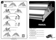
To unpack, follow the steps below (refer to Figure 6);<br />
1. Cut the straps and lift off the carton box.<br />
2. Remove the plastic bag.<br />
3. Remove the four securing bolts (1).<br />
4. Turn down the four leveling feet (2) to lift the machine.<br />
5. Remove the wooden blocks (3).<br />
Figure 6: Removing transport parts.<br />
WARNING:<br />
ROLL OFF <strong>TH</strong>E MACHINE ON <strong>TH</strong>E SHORT<br />
SIDE OF <strong>TH</strong>E PALLET. ON <strong>TH</strong>E LONG SIDE IT<br />
WILL BECOME TOP-HEAVY AND FALL OVER.<br />
6. Place the two ramps (4) to the pallet so that the castors (5)<br />
will run clear from the edge.<br />
7. Unscrew and turn the support block (6) 90° to make room<br />
for the machine to pass by.<br />
8. Turn up the four leveling feet (2) to put the machine on its<br />
castors (5).<br />
9. Roll off the machine from the pallet using the ramps and<br />
put the machine in its final place.<br />
WARNING:<br />
DANGER OFF GETTING CAUGHT UNDER <strong>TH</strong>E<br />
MACHINE. ROLL OFF <strong>TH</strong>E MACHINE BY 2<br />
PERSONS. IT IS HEAVY AND CAN NOT BE<br />
CONTROLLED ALONE.<br />
Note:<br />
Save all packing material for future moving over large<br />
distance or discard of according to local regulations.<br />
Installation 13<br />
English
3.2 Installation<br />
1. Move the machine to its final place.<br />
Note:<br />
Allow ample working space. See Figure 7.<br />
Figure 7: Working space.<br />
L = Maximum board length<br />
S = Minimum space 60 cm<br />
2. Turn down the four leveling feet until the castors are free<br />
from the floor.<br />
3. Level the machine by adjusting the four leveling feet. Put<br />
the spirit level horizontal on the upper main roller and<br />
vertical against the front of both cabinets.<br />
4. Remove all transport material.<br />
• Cut the straps holding the in-feed table arms and lower<br />
the in-feed table.<br />
• Cut the straps and move up the top main roller to<br />
remove the wooden blocks and the transport foam<br />
from the nip.<br />
• Cut the straps around the shaft suspensions and<br />
remove the transport foam.<br />
5. Connect the machine to the mains using the power cable<br />
supplied with the machine.<br />
CAUTION:<br />
Check the mains values before connecting. See<br />
section 2.4.4 for power supply details.<br />
WARNING:<br />
WHEN <strong>TH</strong>E POWER CORD OF <strong>TH</strong>E MACHINE<br />
IS PLUGGED IN, <strong>TH</strong>E MACHINE IS<br />
CONSTANTLY POWERED.<br />
CAUTION:<br />
Only if absolutely necessary, use an extension<br />
cable of ample capacity.<br />
Unroll the extension cable completely.<br />
WARNING:<br />
MAKE SURE <strong>TH</strong>E POWER SUPPLY CABLE<br />
AND/OR <strong>TH</strong>E EXTENSION CABLE IS NOT<br />
BLOCKING YOUR WAY AROUND <strong>TH</strong>E<br />
MACHINE.<br />
14 Installation
HotLam <strong>TH</strong> 2000<br />
The HotLam <strong>TH</strong> <strong>2000N</strong> has higher power consumption and is<br />
therefore supplied with a different mains input and a mains<br />
switch (Figure 8).<br />
Figure 8: Mains switch.<br />
6. Set the Mains switch to ON.<br />
3.3 Transport<br />
The machine can be transported on a smooth surface on its<br />
castors.<br />
CAUTION:<br />
Turn up the leveling feet completely to prevent<br />
them to bend or break when accidentally bumping<br />
into an obstacle.<br />
On rough surfaces use the original pallet and a pallet truck or<br />
forklift.<br />
When moving the machine over large distances, use original<br />
pallet and packing material and follow the unpacking<br />
procedure in the opposite way.<br />
Installation 15<br />
English
4 OPERATING<br />
This chapter describes the function of the controls and<br />
indicators, the operating modes, how to set up and operate<br />
the machine and a number of applications.<br />
4.1 Process controls<br />
This section gives an overview of the controls on the control<br />
panel (Figure 9), the optional heater control (Figure 10) and<br />
elsewhere on the machine (Figure 11).<br />
Note:<br />
Switch on the (optional) heater approximately 1 hour before<br />
use, if a process requires the roller to be heated. Close the<br />
nip and let the machine run at low speed, to avoid irregular<br />
warming up.<br />
4.1.1 Control panel<br />
This paragraph describes the controls and indicators on the<br />
control panel.<br />
When LED’s are blinking, this indicates an error.<br />
Control ON/OFF (1), toggle pushbutton;<br />
Press 1 second to switch the machine from stand by to active<br />
and back.<br />
WARNING:<br />
WHEN <strong>TH</strong>E POWER CORD OF <strong>TH</strong>E MACHINE<br />
IS PLUGGED IN, <strong>TH</strong>E MACHINE IS<br />
CONSTANTLY POWERED.<br />
Figure 9: Control panel<br />
Power indicator (2), LED;<br />
The LED will light when the machine is powered. It flashes<br />
when the machine is in stand-by mode.<br />
Safety indicator (3), LED;<br />
The LED will light when the beam of the optical safety device<br />
at the input side of the nip is not interrupted.<br />
16 Operating
Pressure indication (4), 4 LED’s;<br />
The LED’s indicate the pressure setting of the main rollers.<br />
When 2 LED’s light at the same time, they indicate the tens in<br />
between. See specifications for actual pressure range.<br />
All four LED’s flashing<br />
This indicates a pressure or nip setting error. The LED’s start<br />
flashing at 10% overload. When the pressure exceeds a 20%<br />
overload an audible signal is generated. Increase the nip to<br />
lower the pressure.<br />
NIP setting indication (5), Pointer;<br />
This mechanism is directly coupled with the nip control and<br />
indicates the distance (nip) between the main rollers, set by<br />
the hand wheel.<br />
Slow mode (6), toggle pushbutton;<br />
Press 1 second to switch slow mode ON or OFF.<br />
To run at the fixed slow mode speed the footswitch must be<br />
pressed.<br />
CAUTION:<br />
When slow mode is active the machine can still<br />
run at high speed.<br />
Slow mode indication is NOT a speed indication. It<br />
is a working method.<br />
Slow mode indicator (7), LED<br />
The LED will light when slow mode is selected.<br />
Stop (8), pushbutton;<br />
Press to stop the rotation of the rolls.<br />
Forward (9), pushbutton;<br />
Press to start the rotation of the rolls in the forward direction.<br />
Forward indicator (10), LED;<br />
The LED will light when the forward mode is selected.<br />
Speed control (11), control knob;<br />
Sets the speed anywhere in a range between 0 and 10<br />
(See specifications for actual speed range).<br />
Reverse (12), pushbutton;<br />
Press to start the rotation of the rolls in reverse direction.<br />
Reverse indicator (13), LED;<br />
The LED will light when the rollers are rotating in the reverse<br />
direction (reverse mode).<br />
Forward and Reverse indicator flashing<br />
This indicates a motor overload. Press the stop button and<br />
check the material flow and the tension setting of the unwind<br />
shafts. If the error persists, contact your service organisation.<br />
Operating 17<br />
English
4.1.2 Heater control<br />
Above the control panel a heater control can be installed. This<br />
section controls the temperature of the top main roller<br />
Figure 10: Heater control.<br />
The heater is enabled by the ON/OFF switch (1) and turned<br />
on and off by the temperature control.<br />
When the machine is turned ON, the actual temperature (3)<br />
and the operation mode OP1 (2) will be displayed on the<br />
temperature control.<br />
The heater has a factory defined temperature range. Within<br />
this range the roller temperature can be regulated.<br />
The temperature setting is displayed when the up (7) or down<br />
(6) button is pressed. To change the temperature setting<br />
press the up (7) or down (6) buttons.<br />
The buttons (4) and (5) are not used.<br />
Note:<br />
The heated roller needs time to reach its final temperature<br />
(e.g. from room temperature to maximum takes<br />
approximately 1 hour). Close the nip and let the machine<br />
run at low speed, to avoid irregular warming up.<br />
4.1.3 Additional controls<br />
Figure 11: Additional controls<br />
Emergency stop buttons (1), push and hold button;<br />
When pressed the rotation of the rolls is stopped immediately<br />
and the button is locked into this stop position.<br />
Turn the button to unlock it.<br />
Pressing start, reverse or footswitch starts the process again.<br />
Nip setting wheel (2), geared wheel;<br />
Turn the wheel clockwise to narrow (close) the nip or counterclockwise<br />
to widen (open) the nip.<br />
When both rollers touch the materials, the pressure is set as<br />
follows. By turning the wheel clockwise the pressure is<br />
increased. Turning the wheel counter-clockwise the pressure<br />
will decrease.<br />
The nip setting and the pressure are indicated on the control<br />
panel.<br />
18 Operating
Foot switch (3), snap switch;<br />
Press and hold the switch to start the rotation of the rolls.<br />
Insert the forefoot completely to disable the safety lock that<br />
prevents accidental starting.<br />
When the switch is released, the rotation of the rolls will stop.<br />
Tension control (4), knob;<br />
By turning this knob clockwise a brake is set to the rotation of<br />
the shaft.<br />
Tightening the brake will apply more tension to the material on<br />
the shaft in case.<br />
Turning the knob counter-clockwise will release the brake and<br />
therefore release the tension.<br />
In-feed table (5);<br />
The in-feed table can swing up around pivot point till it is<br />
upside down. In the upper position it is stopped by the shaft<br />
supports and in the lower position by the table stops.<br />
WARNING:<br />
DANGER OF GETTING CAUGHT BETWEEN<br />
TABLE AND CABINET OR MAIN ROLLER.<br />
HOLD <strong>TH</strong>E TABLE IN <strong>TH</strong>E MIDDLE AND<br />
SWING IT UP OR LOWER IT COMPLETELY.<br />
Mains switch (6), 2-position switch;<br />
To switch the mains supply to the machine ON or OFF.<br />
This switch is only present in the <strong>TH</strong><strong>2000N</strong>.<br />
4.2 Operating modes<br />
The machine is either in normal mode or slow mode. In both<br />
modes the rollers can rotate in forward direction and in normal<br />
mode the rollers can also rotate in reverse direction.<br />
4.2.1 Normal forward mode<br />
Normal forward mode can be activated from standstill when<br />
slow mode is not active.<br />
The rotation speed of the rollers in normal mode is set via the<br />
speed control knob.<br />
Rotation is started when the start button is pressed and<br />
stopped when the stop button is pressed.<br />
When the footswitch is pressed, control is taken over by the<br />
footswitch and the rollers will rotate forward until the<br />
footswitch is released.<br />
To return control to the control panel without stopping, press<br />
and hold the start button, release the footswitch and then<br />
release the start button.<br />
An interruption of the light beam of the optical safety device<br />
will stop the rotation of the rollers.<br />
The process can be continued by the start button after the<br />
interruption is taken away.<br />
Operating 19<br />
English
4.2.2 Reverse<br />
Rotation in the reverse direction can only be started from<br />
stand still by pressing the reverse button.<br />
CAUTION:<br />
The unwind shafts will not rewind the material,<br />
they are not motor driven.<br />
Rotation is stopped when the stop button is pressed.<br />
WARNING:<br />
KEEP CLEAR OF <strong>TH</strong>E REAR SIDE NIP WHEN<br />
RUNNING IN REVERSE MODE.<br />
When running in reverse, the optical safety device (at the front<br />
side nip) is disabled.<br />
The speed is determined by the speed control, also when slow<br />
mode is selected.<br />
4.2.3 Slow mode<br />
Slow mode is entered and left by pressing the slow mode<br />
button for 1 second. Selection is indicated by the slow mode<br />
indication LED.<br />
When selecting slow mode from normal forward mode, the<br />
speed (normal speed) will not change until the footswitch is<br />
pressed.<br />
Normal speed<br />
Normal speed in slow mode is still determined by the speed<br />
control setting.<br />
Switching between normal speed and standstill is done by the<br />
start and the stop button.<br />
Slow mode speed<br />
Slow mode speed is a fixed low speed (see specifications)<br />
independent from the speed control. Slow mode speed is only<br />
selected when the footswitch is pressed and held.<br />
WARNING:<br />
KEEP CLEAR OF <strong>TH</strong>E NIP WHEN RUNNING IN<br />
SLOW FORWARD MODE.<br />
When running at slow mode speed, the optical safety device is<br />
disabled.<br />
When the footswitch is released, the forward rotation is<br />
stopped.<br />
To change from slow mode speed to normal speed without<br />
stopping, press and hold the start button, release the<br />
footswitch and then release the start button.<br />
Note:<br />
Changing to normal speed will not deactivate slow mode.<br />
Pressing the footswitch again will slow down rotation to slow<br />
mode speed again.<br />
The combination of slow mode speed and reverse is not<br />
possible.<br />
20 Operating
4.3 Placing film rolls<br />
WARNING:<br />
DANGER OF FINGER OR TOE INJURY WHEN<br />
DROPPING A ROLL. FINGER OR TOE CAN<br />
GET PINCHED BY <strong>TH</strong>E MATERIAL ROLL<br />
AGAINST TIEFRAME OR FLOOR.<br />
When a shaft is not correctly inserted in its suspension, it can<br />
fall out during loading, webbing or running.<br />
4.3.1 Auto-grip shafts<br />
All shafts are equal. Their function is determined by its<br />
position in the machine.<br />
The shafts fit into the machine in both ways. (In older versions<br />
the shafts fit in just one way in the machine.)<br />
On the control panel side of the machine the shaft and the<br />
suspension snap together by a gripper slot and gripper.<br />
At the left-hand side of the machine the shaft has a thrust<br />
piece in the shaft and in the suspension. These thrust pieces<br />
push the shaft into locking position when the shaft is turned.<br />
To position the shaft correctly push it firmly into the<br />
suspensions and turn the shaft until it locks in.<br />
Check the auto-grip mechanism on each shaft. The rubber<br />
cords should just touch the edges of the recess (Figure 12A:<br />
d = 8 ± 2.5 mm).<br />
If not, see chapter 5 Maintenance.<br />
Figure 12: Auto-grip shaft<br />
When the shaft is rotated inside a cylinder, the rubber cord will<br />
move to the side and gets caught between shaft and cylinder<br />
(Figure 12B). Rotating back will release the cord.<br />
Operating 21<br />
English
4.3.2 Use of films with release liner<br />
When in a process film is used with release liner that must be<br />
removed, the wind-up shaft must be loaded with a scrap core<br />
(empty cardboard cylinder) having the same width as the film.<br />
1. Take the auto-grip shaft from the wind-up position of the<br />
machine.<br />
2. Place the scrap core on the shaft, holding the shaft as in<br />
Figure 13.<br />
CAUTION:<br />
Do not drop the end of the shaft on the floor.<br />
3. Put the shaft with cylinder back into the machine.<br />
4. Push the thrust piece side of the shaft firmly into its<br />
suspension.<br />
5. Turn the shaft until the gripper locks in.<br />
4.3.3 Loading shaft with film rolls<br />
The film roll is put on the shaft depending on the type of film<br />
and the use in upper or lower section of the machine.<br />
• In the upper section, the side contacting with the image<br />
must be on the top when unwinding the film to the front of<br />
the machine.<br />
• In the lower section, the side contacting with the image<br />
must be on the bottom when unwinding the film to the front<br />
of the machine.<br />
1. Take the auto-grip shaft from the unwind position of the<br />
machine.<br />
2. Insert the shaft (thrust piece side first) into the core<br />
cylinder of the film roll, holding the auto-grip shaft as in<br />
Figure 13.<br />
Unwind direction of film in the upper section:<br />
• film with release liner towards 1<br />
• film without release liner towards 2<br />
Unwind direction of film in the lower section:<br />
• film with release liner towards 2<br />
• film without release liner towards 1<br />
Figure 13: Auto-grip shaft position.<br />
3. Place the shaft with film roll in the machine.<br />
4. Push the thrust piece side of the shaft firmly into its<br />
suspension.<br />
5. Turn the shaft until the gripper locks in.<br />
6. Position the film and the empty core in the middle.<br />
Note:<br />
When both upper and lower section is used, place both<br />
films at exactly the same position.<br />
7. Make sure the film is set up the right way.<br />
22 Operating<br />
1<br />
2
4.3.4 Presetting the tension<br />
To enable the film to unwind without wrinkles a momentum<br />
(brake or tension) can be set to the roll.<br />
On the right-hand side of the machine you will find tension<br />
control knobs, corresponding with each shaft.<br />
Turn the tension control knob counter clockwise to release the<br />
brake.<br />
When the film is webbed, it is recommended to set a mild<br />
tension to each shaft by turning the knob clockwise until you<br />
feel some resistance.<br />
On the unwind shaft this will prevent film to unwind without<br />
tension. On the motor-driven wind-up shaft it allows the shaft<br />
to slip and adapt its rotation speed to the speed of the film.<br />
4.3.5 Pressure setting<br />
CAUTION:<br />
Remove the pressure and open the nip, to avoid<br />
flattening of the rollers when standing still for a<br />
longer period.<br />
Thin images<br />
When processing thin images (thickness less than the film)<br />
pressure is preset when the upper and lower material is<br />
webbed.<br />
During processing the pressure can be adjusted. The best<br />
pressure setting for thin films is about 40% on the <strong>1100N</strong> and<br />
<strong>1600N</strong> and about 80% on the <strong>TH</strong><strong>2000N</strong>.<br />
Panels<br />
When processing panels, a leader panel is used to preset the<br />
pressure.<br />
Use a leader panel of the same material, thickness and width<br />
as the panels to process.<br />
1. Set the nip to the thickness of the panel.<br />
2. Feed the panel in the nip in slow mode.<br />
3. Set the pressure to approximately 40%.<br />
For the HotLam <strong>TH</strong><strong>2000N</strong><br />
3. Set the pressure to approximately 80% for full-width<br />
panels.<br />
CAUTION:<br />
For narrower panels set the pressure proportional<br />
to the width between 40% and 80%.<br />
E.g. half width equals 60%.<br />
4. Push the reverse button to run the panel back through the<br />
machine.<br />
Operating 23<br />
English
4.4 Webbing<br />
Film with release liner always runs via a splitter bar (or idler)<br />
to separate the release liner from the film.<br />
To get more contact surface with the heated main roller heat<br />
sensitive film also runs via this idler (splitter bar).<br />
A leader panel is always needed to insert the films into the<br />
nip. When panels are processed, it must be of the same<br />
thickness as the panels to process to set correct nip-pressure.<br />
WARNING<br />
DANGER OF GETTING BURN WOUNDS.<br />
MAKE SURE NOT TO TOUCH <strong>TH</strong>E MAIN<br />
ROLLERS WHEN HEATED.<br />
4.4.1 Upper section only<br />
Figure 14: Webbing upper section.<br />
1. Remove the image guide.<br />
2. Unwind the film from the upper or top unwind roll.<br />
• Lead pressure sensitive film (without release liner)<br />
from the top unwind roll over the splitting bar (A).<br />
• Lead all other films underneath the splitting bar (B).<br />
3. Pull the film forward until approximately 10 cm is on the infeed<br />
table.<br />
In case of release liner:<br />
• Peal off the release liner.<br />
• Pull the release liner from the rear side over the windup<br />
shaft.<br />
• Stick it to the scrap core on the wind-up shaft.<br />
4. Stick a leader panel to the film.<br />
5. Feed the panel into the nip using slow mode speed.<br />
6. Refit the image guide.<br />
During processing:<br />
• Check and adjust the tension on the unwind- and wind-up<br />
shafts.<br />
• Check and adjust the pressure setting while feeding<br />
through the leader board or images.<br />
• Now speed can be set to normal.<br />
4.4.2 Upper and lower section<br />
The film in the upper section is webbed first;<br />
1. Lead the film underneath the splitting bar (between splitter<br />
bar and upper roller).<br />
• Pressure sensitive film (without release liner) from the<br />
top unwind shaft has to go over the splitting bar.<br />
24 Operating
2. Pull the film forward till it almost reaches the in-feed table<br />
and apply it to the upper roller.<br />
In case of release liner:<br />
• Peel off the release liner.<br />
• Pull it from the back over the wind-up shaft.<br />
• Stick it onto the cylinder on the wind-up shaft.<br />
Now web the lower section;<br />
Figure 15: Webbing lower section.<br />
3. Lift the in-feed table and put it in the top position.<br />
4. Unwind the film from the lower unwind roll.<br />
• Lead pressure sensitive film without release liner<br />
underneath the splitting bar (A).<br />
• Lead all other films over the splitter bar (B).<br />
5. Pull the film forward till the end reaches above the nip and<br />
stick it to the film from the upper section.<br />
In case of release liner:<br />
• Peel off the release liner.<br />
• Pull it underneath the wind-up shaft.<br />
• Stick it from below onto the cylinder on the wind-up<br />
shaft.<br />
6. Lower the in-feed table and refit the image guide<br />
7. Push the films with a leader panel into the nip using slow<br />
mode speed.<br />
Note:<br />
When laminating (encapsulating) thin images double sided,<br />
it is recommended to use release board as leader.<br />
8. When the leader panel is through the nip, cut off the leader<br />
panel and set the nip to zero.<br />
9. Set the pressure for optimum result.<br />
While feeding test images:<br />
• Check and adjust the pressure setting.<br />
• Now speed can be set to normal.<br />
• Check and adjust the tension on the unwind- and wind-up<br />
shafts (see also section 5.3).<br />
• Let the release liner split off close to the nip to prevent<br />
dust from attaching to the unprotected adhesive layer as<br />
much as possible.<br />
Operating 25<br />
English
4.5 Processes and settings<br />
4.5.1 Mounting images or decals<br />
In this process the machine is not webbed with film.<br />
• When mounting images onto a (pre-coated) board (B), the<br />
adhesive is on the mounting side of the board.<br />
• When mounting decals (A), the adhesive is on the back of<br />
the image.<br />
The mounting process is equal for both.<br />
1. Remove the shafts from the upper section.<br />
2. Preset the nip and the pressure (see section 4.3.5).<br />
3. Put the board on the in-feed table.<br />
6<br />
12 2<br />
1<br />
5<br />
Figure 16: Mounting images or decals<br />
2<br />
3<br />
4<br />
4. Put the image on top of the board (image side up). Turn<br />
back the image at the machine side (1).<br />
5. Turn back approx. 25 mm release liner (2) at the machine<br />
side and crease this evenly from the inside out.<br />
Note:<br />
The final quality depends on the way in which the leading<br />
edge of the image is applied to the board.<br />
6. Apply the image to the board (3).<br />
7. Insert the end with the image adhered to into the nip.<br />
8. Lay the loose end of the image smoothly over the upper<br />
roller (4).<br />
Note:<br />
Use the footswitch to start/stop in slow mode, keeping your<br />
hands free.<br />
9. With your left hand - peel back the release liner (6) from<br />
the image or board as it is slowly fed into the nip one<br />
section at a time, without stopping.<br />
Note:<br />
Removing the release liner completely exposes the<br />
adhesive to dirt and dust that will get trapped under the<br />
image.<br />
10. With your right hand - keep the image smooth against the<br />
upper roller (5), preventing the image to wrinkle.<br />
Note:<br />
For the best result; do not stop while feeding of an image.<br />
26 Operating
4.5.2 Pre-coating panels<br />
This process is used to coat boards (substrates) with a<br />
pressure sensitive mounting film onto which images can be<br />
mounted. This process can also be used to create a carrier<br />
board.<br />
Note:<br />
Mounting film is usually provided with one release liner.<br />
Place the film and web it as if it is without release liner, over<br />
the splitter bar.<br />
1. Place the roll of mounting film on the shaft of the upper<br />
unwind position.<br />
2. Set the nip to correspond to the thickness of the panels to<br />
process.<br />
3. Web the film using a leader board of the same material,<br />
thickness and width.<br />
4. Set the pressure while feeding the leader board.<br />
5. Before the end of the leader board enters the nip, butt up<br />
the panel to be pre-coated.<br />
When more panels have to be pre-coated feed them in<br />
continuously without any gap.<br />
At the end, use a leader board again to finish. This is to<br />
prevent the adhesive to touch the bottom roller.<br />
6. Butt up and feed the ending leader board until the previous<br />
panel is out of the nip.<br />
CAUTION:<br />
Do not cut film close to or on the rollers. This will<br />
damage the silicone coating of the rollers and will<br />
void the warranty.<br />
7. Cut this panel free.<br />
8. Back-up the leader board using the reverse.<br />
9. Cut the film using a blade cutter.<br />
After removing the release liner from the pressure sensitive<br />
mounting adhesive, the board has an adhesive coating ready<br />
to mount an image. See section 4.5.1 for mounting images.<br />
4.5.3 Single-sided lamination<br />
Images are laminated single-sided using carrier (or release)<br />
boards. This laminate can be a heat sensitive laminate or a<br />
pressure sensitive adhesive with release liner.<br />
• The image is put on the carrier board with the image up.<br />
• All steps in this process are equal to steps when precoating<br />
a board (section 4.5.2).<br />
4.5.4 Over-lamination<br />
After an image is mounted to a panel, a protective laminate<br />
can be applied. This over-laminate can be a heat sensitive<br />
laminate or a pressure sensitive adhesive with release liner.<br />
• All steps in this process are equal to steps when precoating<br />
a board (section 4.5.2).<br />
4.5.5 Double-sided lamination<br />
Encapsulating images with cold laminates is called doublesided<br />
lamination (and is normally not done with panels).<br />
On a standard machine (shafts only present in the upper<br />
section), double-sided lamination is done by performing<br />
single-sided lamination twice using a carrier board.<br />
The image side is laminated first. Then the image is put<br />
upside down on the carrier board and laminated again.<br />
Operating 27<br />
English
With the optional lower section installed, double-sided<br />
lamination can be done in one pass.<br />
1. Load and web laminating film in the upper and the lower<br />
section.<br />
2. Stick a leader board to the films and feed it together with<br />
the films through the nip.<br />
3. When the leader board is completely out of the nip, lower<br />
the upper roller onto the lower roller (nip setting = 0).<br />
4. Now feed the images into the nip, allowing a gap between<br />
them.<br />
5. Cut-off the result with the blade cutter when the images<br />
are clearly free from the rollers.<br />
To unload the machine:<br />
6. Cut the film along the splitter bar using a blade cutter.<br />
7. Backup and remove the film between the rollers, using the<br />
reverse.<br />
8. Open up the nip.<br />
4.5.6 Encapsulation<br />
Sealing an image with heat sensitive laminates on both sides<br />
in one pass is called encapsulation.<br />
It can only be done on a (real) HotLam that has heaters<br />
installed on both rollers.<br />
On the HotLam <strong>TH</strong> this process can be imitated by performing<br />
the procedure double-sided lamination on a standard machine<br />
with a heated top roller.<br />
• Switch ON the heater at least a ½ hour before starting<br />
(1 hour for max. temperature).<br />
4.5.7 Decaling<br />
When decaling, a laminate is put over the image side and an<br />
adhesive backing is put on the backside of the image.<br />
So this decal can later be mounted on a panel or other<br />
substrate.<br />
4.5.8 Option and process combinations<br />
Standard version Optional lower section installed HotLam*<br />
Heaters installed None Upper roller None Upper roller Both rollers<br />
Pre-coating (making panels self-adhesive) Yes Yes Yes Yes Yes<br />
Single sided / over lamination Cold only Yes Cold only Yes Yes<br />
Double sided lamination In 2 passes In 2 passes Yes Yes Yes<br />
Decaling Cold only,<br />
in 2 passes<br />
In 2 passes Cold only Yes Yes<br />
Encapsulation No No No No Yes<br />
Media unwind (User installed option) Yes Yes Yes Yes Yes<br />
Result to Roll and Roll to Roll No No No No Yes<br />
* High-end member of this machine range, described in a separate user manual<br />
28 Operating
5 MAINTENANCE<br />
Service activities on this machine must be carried out by<br />
qualified personnel.<br />
5.1 Cleaning<br />
The machine has to be cleaned regularly. Dirt and dust may<br />
influence the result of the lamination processes.<br />
CAUTION:<br />
Do not use abrasive materials for cleaning the<br />
machine. This can damage the painted surfaces or<br />
the silicone covering of the rollers.<br />
Use a damp cloth for cleaning.<br />
CAUTION:<br />
Make sure water does not run into any of the<br />
cabinets. This can damage the electrical circuits<br />
when power is applied.<br />
Clean the exterior of the machine with a damp cloth as<br />
needed. If necessary, use a household-cleaning solution to<br />
remove difficult marks.<br />
Clean the shafts and the rubber cords on it as required.<br />
5.1.1 Cleaning the silicone covered rollers.<br />
The rollers must be cleaned regularly to prevent a build-up of<br />
adhesive residue. This may eventually damage the rollers.<br />
Use a damp lint-free cloth to remove dust and other dirt.<br />
Use a silicone-cleaning block to remove the adhesive stains<br />
from the rollers.<br />
Note:<br />
Adhesive is easier to remove when the rollers are hot.<br />
Put a waste panel between the rollers when cleaning the<br />
upper roller, to prevent adhesive residues from falling onto the<br />
lower roller.<br />
WARNING:<br />
MAKE SURE <strong>TH</strong>E ROLLERS ARE COLD<br />
WHEN USING ALCOHOL FOR CLEANING.<br />
ISOPROPYL ALCOHOL IS EASY<br />
FLAMMABLE.<br />
Difficult stains can be removed with isopropyl alcohol (IPA) on<br />
a clean lint-free cloth.<br />
Do not pour isopropyl alcohol directly on the machine.<br />
Maintenance 29<br />
English
5.2 Preventive maintenance<br />
The machines are designed in such way that they need little<br />
(preventive) maintenance in addition to the cleaning.<br />
The following checks have to be performed:<br />
• Auto-grip shafts with blocking cords.<br />
5.2.1 Auto-grip shafts<br />
Check the auto-grip mechanism on each shaft.<br />
• The distance (d) between the rubber cords and the edges<br />
of the recess should be 8 ± 2.5 mm minimum (the cord<br />
must not touch the skew).<br />
d<br />
Figure 17: Auto-grip shaft<br />
3<br />
A B<br />
If not, correct as follows:<br />
• Loosen the clamp (2) with the screw (1) till the cord is free<br />
on one side.<br />
• Shorten the cord by approximately 10 mm.<br />
• Put back the end of the cord underneath the clamp (2).<br />
• Secure it by tightening the screw (1)<br />
2<br />
1<br />
5.3 Trouble shooting<br />
During processing wrinkles can show up in the image (1) on<br />
the in-feed table (2) and the process result (4) on the output<br />
table.<br />
The figures below show some examples where it is caused by<br />
the main rollers (3) or the pull rollers (5), and gives a possible<br />
solution.<br />
Wait until a few meters are processed to see results.<br />
Pressure too high.<br />
Figure 18: Wrinkles due to high pressure.<br />
• Decrease the nip pressure a little (5-10%).<br />
Pressure too low.<br />
Figure 19: Wrinkles due to low pressure.<br />
• Increase the nip pressure a little (5-10%).<br />
30 Maintenance
Unwind tension too low.<br />
Figure 20: Wrinkles due to low unwind tension.<br />
• Increase the unwind tension until the wrinkles (6) in the<br />
film on the roller disappear. The lines (7) in the result will<br />
disappear as well.<br />
Roller alignment fault.<br />
Figure 21: Wrinkles due to faulty roller alignment.<br />
The wrinkles occur on one side only (left or right).<br />
• This is a machine adjustment error. Contact your dealer<br />
and ask for technical assistance.<br />
Material rolls are jumping.<br />
A regular tick can be heard in the shaft suspension.<br />
• Adjust the shaft support (1) by turning up or down the<br />
screw (2) with an Allenkey.<br />
Figure 22: Shaft support adjustment.<br />
5.4 Technical assistance<br />
For technical assistance you can contact your dealer or the<br />
address on the copyright page in front of this manual.<br />
Make a clear description of the problem before contacting.<br />
Please keep the type and serial number of your machine at<br />
hand.<br />
You can find this data on the identification plate of your<br />
machine, which can be found on the rear side of the righthand<br />
cabinet.<br />
Maintenance 31<br />
English
6 GLOSSARY<br />
Carrier board<br />
A board with a non-stick surface that is used when<br />
laminating one side of an image only.<br />
Decal<br />
An image with an adhesive backside (Am.: Sticker)<br />
Decaling<br />
Providing an image with laminate on the image side and<br />
adhesive on the backside.<br />
Encapsulating<br />
Sandwiching an image between two heat sensitive films.<br />
Laminate<br />
A thin film of clear material to be permanently affixed onto<br />
an image.<br />
Laminating<br />
Providing an image with a thin film of clear material.<br />
Leader board<br />
A piece of stiff card or foam used to lead film into the nip of<br />
the main rollers. In addition this is used when pre-coating to<br />
prevent adhesive getting onto the rollers.<br />
Main rollers<br />
A set of two silicon coated rollers that perform the actual<br />
process.<br />
Mounting<br />
Permanently affixing an image onto a backing board.<br />
Mounting film<br />
Adhesive backing to make an image self-adhesive. On the<br />
side that is in contact with the image the carrier has an<br />
adhesive with or without release liner. The carrier can<br />
function as release liner or be supplied with a second (cold)<br />
adhesive layer and release liner.<br />
Nip<br />
The area where the top and bottom main rollers meet.<br />
Pre-coating<br />
Coating a substrate with an adhesive mounting film onto<br />
which an image can be mounted.<br />
Release board<br />
See carrier board.<br />
Release liner<br />
Backing film protecting the adhesive layer of a laminate or<br />
mounting adhesive. Once the release liner is pealed off, the<br />
adhesive layer becomes exposed.<br />
Roll<br />
A (shaft with a) cylinder loaded with film or release liner.<br />
Roller<br />
One part of the main element in the machine that performs<br />
the actual process (see main rollers).<br />
Scrap core<br />
An empty cardboard cylinder left over when all material on<br />
a roll is used.<br />
Webbing<br />
Loading the machine with film, so that the machine is ready<br />
for processing.<br />
32 Glossary