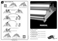
COLDLAM/HOTLAM TH 1100N/1600N/2000N Mounter ... - Neschen
COLDLAM/HOTLAM TH 1100N/1600N/2000N Mounter ... - Neschen
COLDLAM/HOTLAM TH 1100N/1600N/2000N Mounter ... - Neschen

You also want an ePaper? Increase the reach of your titles
YUMPU automatically turns print PDFs into web optimized ePapers that Google loves.
4.3.2 Use of films with release liner<br />
When in a process film is used with release liner that must be<br />
removed, the wind-up shaft must be loaded with a scrap core<br />
(empty cardboard cylinder) having the same width as the film.<br />
1. Take the auto-grip shaft from the wind-up position of the<br />
machine.<br />
2. Place the scrap core on the shaft, holding the shaft as in<br />
Figure 13.<br />
CAUTION:<br />
Do not drop the end of the shaft on the floor.<br />
3. Put the shaft with cylinder back into the machine.<br />
4. Push the thrust piece side of the shaft firmly into its<br />
suspension.<br />
5. Turn the shaft until the gripper locks in.<br />
4.3.3 Loading shaft with film rolls<br />
The film roll is put on the shaft depending on the type of film<br />
and the use in upper or lower section of the machine.<br />
• In the upper section, the side contacting with the image<br />
must be on the top when unwinding the film to the front of<br />
the machine.<br />
• In the lower section, the side contacting with the image<br />
must be on the bottom when unwinding the film to the front<br />
of the machine.<br />
1. Take the auto-grip shaft from the unwind position of the<br />
machine.<br />
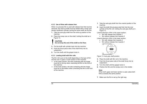
2. Insert the shaft (thrust piece side first) into the core<br />
cylinder of the film roll, holding the auto-grip shaft as in<br />
Figure 13.<br />
Unwind direction of film in the upper section:<br />
• film with release liner towards 1<br />
• film without release liner towards 2<br />
Unwind direction of film in the lower section:<br />
• film with release liner towards 2<br />
• film without release liner towards 1<br />
Figure 13: Auto-grip shaft position.<br />
3. Place the shaft with film roll in the machine.<br />
4. Push the thrust piece side of the shaft firmly into its<br />
suspension.<br />
5. Turn the shaft until the gripper locks in.<br />
6. Position the film and the empty core in the middle.<br />
Note:<br />
When both upper and lower section is used, place both<br />
films at exactly the same position.<br />
7. Make sure the film is set up the right way.<br />
22 Operating<br />
1<br />
2