Manual - Ruberkon
Manual - Ruberkon
Manual - Ruberkon

You also want an ePaper? Increase the reach of your titles
YUMPU automatically turns print PDFs into web optimized ePapers that Google loves.
WARNING<br />
WARNING<br />
WARNING<br />
WARNING<br />
BUILDING HINT<br />
6
1<br />
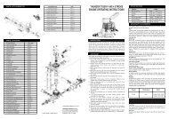
MAIN FRAME ASSEMBLY<br />
For the kit, parts are bagged according to each major assembly and are labeled "Bag A, Bag<br />
B, etc." The heading for each assembly indicates which bag to open. As a good practice,<br />
only open up the bag that you need for the particular assembly. Check the parts in that bag<br />
against the parts list shown for each assembly as well as each sub-assembly to make sure<br />
there are no missing parts. To prevent losing small hardware, please empty the small nuts<br />
and bolts and parts into small plastic trays on your work table. At the end of each major<br />
assembly, there should be no left over parts.<br />
7
1-4<br />
Installation of Servo Frame<br />
BAG C<br />
No. Material No. Description<br />
Qty.<br />
1 BK0667 Servo Frame 1<br />
2 HSE3-12B M3x12 Self-Tapping Screw 6<br />
3 1-3 Main Frame Assembly 1<br />
Install the one-piece servo frame using six self-tapping screws.<br />
Do not use Loctite when attaching self-tapping screws to plastic<br />
parts. Loctite is only for threading metal into metal parts.<br />
(3)<br />
(2)<br />
(1)<br />
13
1-5-1 Aileron Lever Subassembly<br />
No. Material No. Description<br />
Qty.<br />
1 HMJ2-10N M2x10 Self-Tapping Screw 2<br />
2 HMV840ZZ d4xD8x3 BRG 2<br />
3 BK0340 Aileron Control Arm 1<br />
4 BK0075 Link Ball 4.8 2<br />
Add a tiny drop of thick CA glue at the tip of the M2x10<br />
self-tapping screw (No. 1) before screwing it into the<br />
Aileron Levers.<br />
(L)<br />
(3)<br />
(4)<br />
No. Material No. Description<br />
Qty.<br />
1 HMJ2-10N M2x10 Self-Tapping Screw 2<br />
2 HMV840ZZ d4xD8x3 BRG 2<br />
3 BK0340 Aileron Control Arm 1<br />
4 BK0075 Link Ball 4.8 2<br />
(R)<br />
(3)<br />
(2)<br />
(1)<br />
(2)<br />
(4)<br />
(1)<br />
Add CA glue<br />
Add CA glue<br />
1-5-2 Elevator Parallel Lever Subassembly<br />
No. Material No. Description<br />
Qty.<br />
1 HMJ2-10N M2x10 Self-Tapping Screw 1<br />
2 BK0337 Elevator Arm Parallel Lever 1<br />
3 BK0075 Link Ball 4.8 1<br />
(2)<br />
Add CA glue<br />
(1)<br />
(3)<br />
1-5-3 Elevator Control Lever Subassembly<br />
No. Material No. Description<br />
Qty.<br />
1 HMJ2-14N M2x14 Self-Tapping Screw 1<br />
2 HMV840ZZ d4xD8x3 BRG 2<br />
3 BK0338 Elevator Control Lever 1<br />
4 BK0075 Link Ball 4.8 2<br />
(3)<br />
(2)<br />
Add CA glue<br />
(1)<br />
(4)<br />
15
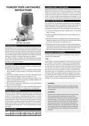
2<br />
ROTOR HEAD ASSEMBLY<br />
19
2-1 Rotor Head Assembly BAG F<br />
No. Material No. Description Qty.<br />
1 BK0292 2.3x24 Link Rod 2<br />
2 HMC3-10B M3x10 Socket Screw 2<br />
3 HMV694ZZ d4xD11x4 BRG 2<br />
4 BK0408 Collar d3xD4x5.5 2<br />
No. Material No. Description Qty.<br />
5 BK0086 Ball Link 4.8 4<br />
6 2-1-1 Flybar Seesaw Subassembly 1<br />
7 2-1-2 Main Rotor Hub Subassembly 1<br />
Make two pushrods for controlling blade pitch. The distance of 43 mm is measured between the center of two pushrod holes.<br />
Attach the Seesaw Hub of the Control Paddle Assembly to the Main Rotor Head with No.2 Socket Screws, No. 3 Bearing.<br />
Please add a small drop of Loctite along the entire length of the M3x10 Socket Screw (No.2 ) and on the outside of the collar<br />
d3xD4x5.5(No.4).<br />
Link the pushrod onto the Rotor Grip and Mixing Lever (See illustration in P.28)<br />
(5)<br />
43mm<br />
(1)<br />
(6)<br />
(4)<br />
(3)<br />
(2)<br />
(5)<br />
(1)<br />
(7)<br />
20
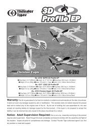
3<br />
TAIL ASSEMBLY<br />
23
No. Material No. Description Qty.<br />
1 HMM3B M3 Locknut 4<br />
2 HSE3-12B M3x12 Self-Tapping Screw 2<br />
3 HMC3-20B M3x20 Socket Screw 2<br />
4 HMC3-25B M3x25 Socket Screw 4<br />
No. Material No. Description<br />
Qty.<br />
5 BK0087 d3xD8x1.4 Washer 2<br />
6 3-1 Tail Assembly 1<br />
7 4-3-1 Tail Support Subassembly 2
No. Material No. Description<br />
Qty.<br />
1 HML2 M2 Nut 4<br />
2 HMF2-8N M2x8 Philip Machine Screw 4<br />
3 BK0436 2.3x55 Link Rod 2<br />
4 BK0438 2.3x88 Link Rod 1<br />
5 HSE2614N 2.6x14 Self Tapping Screw 12<br />
6 HME4-5B M4x5 Set Screw 2<br />
No. Material No. Description<br />
Qty.<br />
7 ***** Servo 5<br />
8 BK0105 Rod Joint 1<br />
9 BK0347 Tail Control Rod A (In BAG O) 1<br />
10 BK0075 Link Ball 4.8 4<br />
11 BK0086 Ball Link 4.8x20 7<br />
12 BK0104 Servo Mounting Plate 6
6<br />
SETTINGS<br />
38
Always operate or fly a model helicopter in a safe manner and away from crowd, or spectators,<br />
or distractions.<br />
Do not operate model helicopters in rainy or windy condition.<br />
Check to make sure there is no radio interference before operating a model helicopter.<br />
Make sure the transmitter and receiver batteries are fully charged before operation.<br />
Make sure all controls operate properly before flight.<br />
Model helicopter main and tail rotors operate at high rpm, therefore make sure nothing can come<br />
into contact with the rotors during flight.<br />
Use only model engine fuel. Do not use gasoline, kerosene, or any other substitute.<br />
Model engine fuel is highly flammable.<br />
Attention<br />
Do not let model engine fuel get in contact with eyes. Do not intake model engine fuel.<br />
Range check the radio before flying. The servos must operate properly with the transmitter<br />
antenna collapsed and at 20 meters away.<br />
The engine must be in the idle position before starting the engine.<br />
Make sure the transmitter and receiver are turned on before starting the engine.<br />
Always maintain a safe distance when operating a model helicopter.<br />
Do not fly a model helicopter above people or cars.<br />
Flying requires concentration. Operating a model helicopter for extended time can cause fatigue.<br />
Please rest in between flights.<br />
Do not touch the engine or muffler immediately after the engine was run, because they will be<br />
extremely hot.<br />
Warning (Items to watch out after flight)<br />
Inspect the model helicopter thoroughly to make sure nothing is loosen or damaged.<br />
Pump out the remaining fuel from the fuel tank.<br />
Lubricate every moving part with oil to ensure a smooth operation in the future.<br />
Warning (For Storage)<br />
Keep the model in a cool, dry place. Avoid storage under direct sun light or near heat.<br />
Add some engine after-run oil through the carburetor, then crank the engine by an electric starter.<br />
This help to prevent the engine bearings from rusting. After-run oils are available from hobby<br />
shops.<br />
Please replace any damaged parts if they are discovered during maintenance.<br />
43
Preflight Checklist and Starting Procedure<br />
Control system check.<br />
(1) The flybar and control paddles must tilt in the proper direction and smoothly through the whole range.<br />
(2) The rotor shaft and flybar must be straight and not damaged.<br />
(3) The swashplate must remain clean and tilts freely.<br />
(4) When control input are given to tilt the swashplate, make sure none of the control arms and pushrods<br />
show any binding.<br />
(5) The two control paddles must be leveled and parallel to each other, and point in the correct direction.<br />
(6) Check to make sure there is no radio interfence before operating the model helicopter.<br />
(7) Make sure the transmitter and receiver are on and all controls operate properly before flight. Range<br />
check the radio.<br />
(8) The engine carburetor must be in the idle position before starting the engine. Please read the engine<br />
instruction manual on how to properly adjust the engine. Set the carburetor main needle according to<br />
the engine instruction. Depends on the fuel and glow plug used, the carburetor idle screw may require<br />
fine adjustment of 1/4 to 1/2 turns away from the factory setting.<br />
(9) Fuel up the tank, move the throttle stick to idle, and connect a specially designed glow plug battery to<br />
the glow plug.<br />
(10)Use a 12 volt model engine electric start<br />
along with a6mmhexstarter extension<br />
(sold separately) to start the engine.<br />
Always grab on the helicopter<br />
main rotor head when<br />
starting the engine.<br />
Otherwise, the main<br />
rotor may start spinning<br />
immediately after the<br />
engine is started.<br />
44
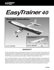
Flying Adjustments (1)<br />
Tracking adjustment ... When the two main rotor blades are in track it means their blade tips<br />
should follow the same path as they rotate.<br />
(1) Rev up the motor until the helicopter becomes<br />
light on its skids.<br />
(2) When the two main rotor blades are in<br />
track it means their blade tips should follow<br />
the same path as they rotate, then it's ok.<br />
increase<br />
throttle gently<br />
and not too<br />
much<br />
(3) When two blades are in track, the blade tips will<br />
appear overlapped as one look at the rotor tip<br />
path plane from the edge.<br />
out of track<br />
If the blades are out of track, then adjust<br />
one of the pushrods that connects to the<br />
main rotor blade pitch arm.<br />
Redo steps (1) to (3) until<br />
the blades are tracking<br />
properly.<br />
in track<br />
In hover, the main blades should be<br />
around 5.5 to 6 degrees in pitch.<br />
45
Flying Adjustments (2)<br />
Trimming: All helicopters are inherently unstable. But when a helicopter is properly trimmed, it<br />
will not drift away or yaw by itself quickly. Use the following procedure to trim your<br />
helicopter.<br />
(1) If the helicopter nose starts to yaw left or right,<br />
then use the transmitter trim to compensate:<br />
yaw right<br />
yaw left<br />
(A) situation: move to (b)<br />
(B) situation: move to (a)<br />
(2) If the helicopter rolls to left or right, then:<br />
rolls right<br />
rolls left<br />
(C) situation: move to (d)<br />
(d) situation: move to (c)<br />
(3) If the helicopter noses down or up, then:<br />
Noses down<br />
Noses up<br />
(E) situation: move to (f)<br />
(F) situation: move to (e)<br />
46
Hover Training (1)<br />
Hovering is when the helicopter is floating in a stationary position in the air. Hovering is the<br />
fundamental manuever to learn first. Here is the procedure to practice hovering:<br />
(1) Make sure there is no spectator anywhere<br />
near the model helicopter. You, the pilot,<br />
should stand at least 10 meters (30 feet)<br />
behind and slightly to the side of the model<br />
helicopter.<br />
(2) Prior to lifting off, while the main rotor is spinning and the helicopter is<br />
on the ground, check the main rotor fore/aft and left/right cyclic to make<br />
sure the main rotor is tilting in the correct direction according to your<br />
cyclic command. Move the tail rotor control stick to make sure the<br />
helicopter nose will swing in the desired direction accordingly.<br />
(3) Increase the throttle/collective to lift the model helicopter skids off the<br />
ground to no more than 10 cm(4 inches). Initially, it will be very difficult<br />
to control the model to prevent it from moving. For a beginner it will<br />
also be difficult to determine whether the helicopter is in trim or not.<br />
But with repeated practice close to the ground you will develop a feel<br />
for the controls. It is recommended to let a more experienced model<br />
helicopter pilot trim out your new model before you attempt to learn<br />
to hover.<br />
47
(4) It will take a few hours of hover practice with the helicopter skids at 10 to 20 cm (4-8 inches)<br />
off the ground in order to comfortably control the model.<br />
Do not try to lift the model to more than 10 to 20 cm(4-8 inches) in the beginning because<br />
then the model may tip over readily when the beginner panics and an incorrect command is<br />
given. Once you can keep the model at one place, then it is time to slowly increase the height<br />
a few centimeters (inches) in each flight. Soon, you will be able to hover the helicopter<br />
confidently at few feet high. Beginners should always practice hovering close to the ground<br />
because in an emergency panic, throttle and collective can be reduced rapidly without causing<br />
a large drop or damage to the model. If the model was hovering at beyond one meter(3 feet)<br />
altitude, then always descend slowly. A panic drop can damage the helicopter.<br />
(5) Always stand behind the model helicopter when learning how to hover because then you<br />
can watch the nose of the helicopter, and a left tail rotor command will yaw the helicopter<br />
nose to the left, and a right command will yaw to the right. Similarly, a left cyclic command<br />
will cause the helicopter to translate left. After you can comfortably hover the model at one<br />
meter high without drifting, then start practice hovering while standing to either side of the<br />
model. Eventually, you need to be comfortable<br />
at hovering the model from any orientation,<br />
including with the helicopter nose pointing at<br />
you, this is challenging because all control<br />
directions are seem backward.<br />
(6) Once you can confidently hover a model helicopter at any altitude and at any orientation,<br />
then congratulate yourself because you have mastered 80% of the fundamental control<br />
movements of a helicopter.<br />
48
Forward Flight Training<br />
After mastering hovering flight:<br />
(1) Start practicing moving the helicopter laterally to the left or right slowly from a 1.5 meter (60<br />
inches) high hover. This is the beginning exercise of translational flight.<br />
hovering at 1-1.5 meter<br />
(2) After a few hours of practicing step (1) and you are comfortable with translational movement,<br />
start using some tail rotor control so the helicopter nose will point slightly to the left or right<br />
as you fly it to the left or right. Eventually, this pattern will become a figure-eight in front of<br />
you. Please visualize these movements in your mind.<br />
49
After Flight Checklist<br />
The model helicopter should be thoroughly inspected after each flying session.<br />
(1) Check every screw and bolt to make sure none has loosened due to vibration.<br />
(2) Check every rotating and movable part to ensure they still move smoothly and normally.<br />
(3) Clean off the exhaust residue from the muffler, engine, and helicopter.<br />
(4) Check all movable parts, such as gears, ball links, belt, etc. for unusual wear.<br />
Trouble Shooting<br />
[1]The engine will not start.<br />
* The engine starting shaft will not turn:<br />
The engine may be flooded with too much fuel. Please remove the glow plug first, then turn the engine<br />
with the electric starter until the excess fuel spits out of the glow plug hole.<br />
* The engine turns when the electric starter is applied, but the engine will not start:<br />
(1) Is the glow plug working? Remove the glow plug and does the platinum coil glow red when a 1.5<br />
volt battery is applied to the plug? The glow plug battery may be weak and old.<br />
(2) Is the carburetor needle properly set? Please refer to the engine instruction manual for the proper<br />
needle setting.<br />
(3) Does the throttle control arm move properly and in the correct direction according to your transmitter<br />
command?<br />
* Engine will start, but quits immediately.<br />
(1) Use the transmitter to increase the throttle carburetor slightly.<br />
(2) Try a new or different type of glow plug. There are different types of glow plugs on the market for<br />
different types of fuel and operating conditions. Seek the advice of experienced fliers and also<br />
experiment with different types of glow plugs until you find the one that suits your operating condition<br />
the best.<br />
*Engine runs, but the helicopter will not lift off.<br />
(1) Check the main rotor blade pitch angle, they should be set at 5.5 to 6 degrees when the transmitter<br />
throttle/collective stick is at the center position.<br />
(2) Does the engine throttle arm move properly? The carburetor opening should be fully open when<br />
the transmitter throttle/collective stick is moved up. The carburetor opening should be nearly closed<br />
when the transmitter throttle/collective stick is moved down. And the opening should be completely<br />
closed when the transmitter throttle/collective stick is moved down and the throttle trim is also moved<br />
down.<br />
(3) The carburetor needle is not set properly. Close the needle (turn it clockwise) all the way, then<br />
open the needle (turn it counter clockwise) 1 and 1/2 turns and try again. If the model still will not<br />
lift, then the engine maybe running too rich. The symptom is the engine exhaust has a lot of smoke<br />
and the engine coughs and wants to quit when the transmitter throttle/collective stick is moved up,<br />
then close the needle 1/8 turn at a time, until the model will lift off. Do not turn the needle too far<br />
inward, that will make the engine run too lean and over-heat and damage the engine.<br />
[2] Helicopter problems.<br />
* The helicopter shakes.<br />
(1) Is the blade spindle bent?<br />
(2) Is the flybar bent?<br />
(3) Is the main rotor shaft bent?<br />
(4) Are the two control paddles mounted at the same distance from the rotor shaft, and the paddles<br />
are parallel to each other, and in the proper direction?<br />
(5) Is the tail rotor shaft bent? The tail rotor blades mounted properly or damaged?<br />
(6) Are the main rotor blades damaged or mounted in the proper orientation? The blade may require<br />
additional balancing. The blade balance can be checked by removing both blades and then use<br />
one of the 5mm blade bolt and nut to hold the two blades together like a teeter totter. Then, hold<br />
the blade bolt with your thumb and index finger. The two blades should teeter and remain in a<br />
level position. If not, then add some tape to the lighter blade near the blade tip until the two blades<br />
teeter in a level position. Hobby shops also sell blade balancers that are designed solely for balancing<br />
model helicopter blades.<br />
50
In the event the model has crashed.<br />
Inspect the flybar, rotor shaft and the blade spindle to make sure they are not bent at all. If any item is damaged, it<br />
must be replaced by a new part to ensure safe operation. Do not glue any broken or damaged plastic part. Do not<br />
repair broken rotor blades. Always inspect the following items immediately:<br />
(a). Engine starting shaft.<br />
(b). All the gears.<br />
(c). Main shaft, flybar and blade feathering spindle.<br />
(d). Tail boom and supports for cracks.<br />
(e). Drive shaft for the tail rotor.<br />
(f). Vertical and horizontal fins.<br />
(g). Tail rotor shaft and control system.<br />
(h). Main and tail rotor blades.<br />
(i). Main frame.<br />
51
No. NAME Parts No. Parts Name quantity Reference<br />
Assembly Step<br />
PV0041 BALL LINK BK0086 Ball Link 4.8x20 12<br />
PV0046 ELEVATOR ARM ,BRG HMV1280 d8xD12x3 BRG 2 1-5-4<br />
PV0048 BRG:PITCH FRAME & ROTOR HUB SEESAW HMV840ZZ d4xD8x3 BRG 2<br />
4830 / LEVER & PITCH ARM 4870<br />
PV0050 BRG:FEATHERING 4830/TAIL SHAFT HMV1350 d5xD13x4 BRG 2 3-1-1<br />
PV0052 TAIL SLIDER BRG HMV1060 d6xD10x3 BRG 2 3-1-2<br />
PV0054 SERVO MOUNTING PLATE BK0104 Sever Mounting Plate 10 5-1, 5-2<br />
PV0058 LINK BALL BK0075 Link Ball 4.5 12<br />
PV0062 BODY MOUNT RUBBER GROMMENTS BK0102 d3xD6x11 RUBBER Grommet 5 5-4-1<br />
PV0120 MAIN ROTOR GRIP BK0075 Link Ball 4.8 2 2-1-2<br />
BK0319 Main Rotor Pitch Housing 2 2-1-2<br />
HMJ2-10N M2X10 Self-Tapping Screw 2 2-1-2<br />
PV0123 MIXING LEVER BK0324 Mixing Lever 2 2-1-1<br />
BK0075 Link Ball 4.8 4 2-1-1<br />
BK0410 Collar d3xD4x13 2 2-1-1<br />
HMC3-18B M3x18 Socket Screw 2 2-1-1<br />
BK0088 d3xD5x0.5 Washer 2 2-1-1<br />
HMJ2-10N HMJ2-10N 4 2-1-1<br />
PV0124 FLYBAR CONTROL ROD BK0344 Flybar Control Rod 2 2-1-1<br />
PV0125 THRUST WASHER BK0325 Thrust Collar 2 2-1-2<br />
PV0126 SPINDLE BK0326 Spindle 1 2-1-2<br />
BK0477 Washer 2 2-1-2<br />
HMC4-10B M4x10 Socket Screw 2 2-1-2<br />
PV0131 ELEVATOR ARM BK0020 Elevator Arm Shaft 1 1-5<br />
BK0075 Link Ball 4.8 1 1-5-2<br />
BK0335 Elevator Arm Link 2 1-5-5<br />
BK0337 Elevator Arm Parallel Lever 1 1-5-2<br />
BK0339 Elevator Control Arm 1 1-5-5<br />
BK0413 Pin 2x29 2 1-5-5<br />
HMJ2-8N M2x8 Self-Tapping Screw 1 1-5-2<br />
HMJ3-20N M3x20 Self-Tapping Screw 2 1-5<br />
PV0132 PITCH CONTROL ARM BK0075 Link Ball 4.8 2 1-5-4<br />
BK0336 Pitch Frame 1 1-5-4<br />
BK0407 Collar d3xD4x13 1 1-5<br />
HMC3-10B Elevator Control Lever 1 1-5<br />
HMC3-25B M2x14 Self-Tapping Screw 1 1-5<br />
HMJ2-10N M2x10 Sefl-Tapping Screw 1 1-5-2<br />
PV0133 ELEVATOR LEVER BK0075 Link Ball 4.8 2 1-5-3<br />
BK0088 d3xD5x0.5 Washer 1 1-5<br />
BK0410 Collar d3xD4x13 1 1-5<br />
BK0338 Elevator Control Lever 1 1-5-3<br />
HMJ2-14N M2x14 Self-Tapping Screw 1 1-5-3<br />
PV0134 AILERON LEVER BK0075 Link Ball 4.8 4 1-5-1<br />
BK0340 Aileron Control Arm 2 1-5-1<br />
BK0410 Collar d3xD4x13 2 1-5-1<br />
HMJ2-10N M2x10 Sefl-Tapping Screw 4 1-5-1<br />
HMJ3-20N M3x20 Self-Tapping Screw 2 1-5<br />
PV0135 TAIL PITCH CONTROL LEVER BK0075 Link Ball 4.8 1 3-1-1<br />
BK0076 Collar d3xD4x10 1 3-1-1<br />
BK0088 d3xD5x0.5 Washer 1 3-1-1<br />
BK0346 Tail Pitch Control Lever 1 3-1-1<br />
HMJ2-8N M2x8 Self-Tapping Screw 1 3-1-1<br />
HMJ3-20N M3x20 Self-Tapping Screw 1 3-1-1<br />
PV0137 MAIN SHAFT LOCK RING BK0234 Lock Ring 1 1-6<br />
HMC3-6B M3x6 Socket Screw 2 1-6<br />
PV0139 ONE WAY CLUTCH SHAFT BK0359 One Way Clutch Shaft 1 1-6-3<br />
HMC4-25B M4x25 Socket Screw 1 1-6-3<br />
HMM4B M4 Locknut 1 1-6-3<br />
HMQ16 Retaining Ring 1 1-6-3<br />
PV0140 TAIL DRIVE GEAR SET BK0362 Tail Drive Bevel Gear A 1 1-2-2<br />
BK0363 Tail Drive Bevel Gear B 1 1-2-2<br />
BK0364 Tail Drive Pinion 1 1-2-2<br />
BK0414 Pin 2x12 2 1-2-2<br />
HME3-4B M3x4 Set Screw 2 1-2-2<br />
58
No. NAME Parts No. Parts Name quantity Reference<br />
Assembly Step<br />
PV0141 ENGINE MOUNT BK0349 Engine Mount 1 1-2<br />
BK0435 d4xD11x1.7 Washer 4 1-2<br />
HMC4-12B M4x12 Socket Screw 4 1-2<br />
HMC4-18B M4x18 Socket Screw 4 4-2<br />
PV0147 TAIL CASE BK0370 Tail Case L 1 3-1-1<br />
BK0371 Tail Case R 1 3-1-1<br />
HMC3-10B M3x10 Socket Screw 3 3-1-1<br />
HMM3B M3 Locket 3 3-1-1<br />
PV0148 TAIL ROTOR GRIP BK0302-1 Tail Pitch Housing A 2 3-1-2<br />
BK0303-1 Tail pitch Housing B 2 3-1-2<br />
HMC26-10B M2.6x10 Socket Screw 4 3-1-2<br />
HMC3-14B M3x14 Socket Screw 2 3-1-2<br />
HMM26B M2.6 Locknut 4 3-1-2<br />
HMM3B M3 Locknut 2 3-1-2<br />
PV0149 TAIL BEVEL GEAR BK0372 Tail Input Bevel Gear 1 3-1-1<br />
BK0373 Tail Output Bevel Gear 1 3-1-1<br />
BK0414 Pin 2x12 1 3-1-1<br />
HME3-4B M3x4 Set Screw 1 3-1-1<br />
PV0150 TAIL ROTOR SHAFT BK0374 Tail Shaft 1 3-1-2<br />
BK0414 Pin 2x12 1 3-1-2<br />
HME3-4B M3x4 Set Screw 1 3-1-2<br />
PV0151 TAIL ROTOR HUB BK0307 Tail Rotor Hub 1 3-1-2<br />
HME3-18B M3x18 Set Screw 2 3-1-2<br />
HMM3B M3 Locknut 2 3-1-2<br />
PV0154 MAIN SHAFT LOWER BRG CASE BK0387 Lower BRG Case 2 1-2-1<br />
PV0155 PITCH GUIDE COLLAR SET BK0384 Pitch Guide Collar L 1 1-2-1<br />
BK0385 Pitch Guide Collar R 1 1-2-1<br />
PV0157 REAR FRAME SET BK0380 Rear Frame L 1 1-2<br />
BK0381 Rear Frame R 1 1-2<br />
BK0629 Washer 4 1-2<br />
PV0158 TAIL BOOM BRACKET BK0382 Tail Boom Bracket L 1 1-2-2<br />
BK0383 Tail Boom Bracket R 1 1-2-2<br />
PV0162 FLYBAR PADDLE SET BK0406 Paddle Root 2 2-1-1<br />
BK0416 Paddle Stopper 2 2-1-1<br />
BK0432 Flybar Paddle 2 2-1-1<br />
HME4-3B M4x3 Set Screw 4 2-1-1<br />
PV0163 TAIL ROTOR BLADE BK0404 Tail Rotor Blade 2 3-1<br />
PV0164 TAIL FIN BK0399 Vertical Fin 1 3-1<br />
BK0400 Stabilizer Fin 1 3-1<br />
BK0401 Stabilizer Fin Bracket 1 3-1<br />
HMC3-30B M3x30 Socket Screw 2 3-1<br />
HMM3B M3 Locknut 2 3-1<br />
HSE3-12B M3x12 Self-Tapping Screw 2 3-1<br />
PV0169 LINKAGE ROD BK0093 2x46 Link Rod 3 1-5<br />
BK0292 2.3x24 Link Rod 2 2-1<br />
BK0318 2.3x95 Link Rod 2 4-1<br />
PV0170 MAIN SHAFT BRG HMV6901ZZ d12xD24x6 BRG 2 1-1-1, 1-2-1<br />
PV0171 BODY BK0098 Body Clip A 1 5-4-1<br />
BK0099 Body Clip B 1 5-4-1<br />
BK0102 d3xD6x11 RUBBER Grommet 2 5-4-1<br />
BK0428 Canopy 1 5-4-1<br />
BK0429 Body 1 5-4-1<br />
HMJ2-6B M2x6 Self-Tapping Screw 8 5-4-1<br />
HSE3-12B M3x12 Self-Tapping Screw 2 5-4-1<br />
PV0172 THRUST BRG HMX0816 d8xD16x5 Thrust Bearing 2 2-1-2<br />
PV0174 FLY BAR SEESAW BRG HMV694ZZ d4xD11x4 BRG 2 2-1-1<br />
PV0175 FEATHERING BRG HMV1680 d8xD16x5 BRG 2 2-1-2<br />
PV0176 TAIL PITCH CONTROL LEVER BRG HMV740ZZ d4xD7x2.5 BRG 2 3-1-1<br />
PV0177 ROTOR BOLT BK0446 Rotor Bolt 2 5-5<br />
HMM5Z M5 Locknut 2 5-5<br />
PV0182 CLUTCH BELL BRG HMV1360Z d6xD13x5 BRG 2 1-1-2<br />
PV0183 BODY RETAINING SET BK0103 Body Fitting Pin 2 5-4-1<br />
HSA3-22 M3x22 Button Head Socket Screw 2 5-4-1<br />
PV0184 FLYBAR SEESAW BK0322 Flybar Seesaw Hub 1 2-1-1<br />
59
No. NAME Parts No. Parts Name quantity Reference<br />
Assembly Step<br />
BK0408 Collar d3xD4x5.5 2 2-1<br />
HMC3-10B M3x10 Socket Screw 2 2-1<br />
PV0186 MAIN SPUR GEAR 93T(STD) BK0420 Main Spur Gear 93T 1 1-6-3<br />
PV0188 MAIN SPUR GEAR 95T(OPT) BK0431 Main Spur Gear 95T 1 1-6-3<br />
PV0189 MAIN SPUT GEAR 94T(OPT) BK0421 Main Spur Gear 94T 1 1-6-3<br />
PV0190 TAIL DRIVE SPUR GEAR BK0357 Tail Drive Spur Gear 83T 1 1-6-3<br />
HMC4-25B M4x25 Socket Screw 1 1-6-3<br />
HMM4B M4 Locknut 1 1-6-3<br />
PV0191 PINION GEAR 10T(OPT) BK0355 Drive Pinion 10T 1 1-1-2<br />
BK0366 Pinion Gear Nut 1 1-1-2<br />
PV0192 PINION GEAR 11T(STD) BK0422 Drive Pinion 11T 1 1-1-2<br />
BK0366 Pinion Gear Nut 1 1-1-2<br />
PV0193 PINION GEAR 12T(STD) BK0423 Drive Pinion 12T 1 1-1-2<br />
BK0366 Pinion Gear Nut 1 1-1-2<br />
PV0195 TAIL DRIVE SHAFT BRG BV0423 Tail Drive Shaft BRG 1 3-1-3<br />
PV0197 TAIL DRIVE SHAFT BEVEL GEAR BRG HMV6701Z d12xD18x4 BRG 2 3-1-1<br />
PV0198 COOLING FAN ASSY BV0380 Cooling Fan Assy 1 4-2-1<br />
PV0200 TAIL ROTOR BRG HMV1050 d5xD10x4 BRG 4 3-1-2<br />
PV0203 STARTER SHAFT BRG HMV696Z d6xD15x5 BRG 2 1-1-2<br />
PV0204 CLUTCH LINER BK0354 Clutch l iner 1 1-1-2<br />
PV0206 CANOPY BK0428 Canopy 1 5-4-1<br />
HMJ2-6B M2x6 Self-Tapping Screw 8 5-4-1<br />
PV0208 FUEL TANK RUBBER GROMMENT BK0274 Tank Rubber Grommet 4 1-2<br />
PV0209 WASHER,d4xD11xt1.7 BK0435 d4xD11x1.7 Washer 4<br />
PV0210 WASHER,d3xD8xt1.4 BK0087 d3xD8x1.4 Washer 16<br />
PV0211 SOCKET SCREW,M2.6x10 HMC2610B M2.6x10 Socket Screw 20<br />
PV0212 SOCKET SCREW,M3x10 HMC3-10B M3x10 Socket Screw 20<br />
PV0213 SOCKET SCREW,M3x12 HMC3-12B M3x12 Socket Screw 20<br />
PV0214 SOCKET SCREW,M3x14 HMC3-14B M3x14 Socket Screw 20<br />
PV0215 SOCKET SCREW,M3x18 HMC3-18B M3x18 Scket Screw 20<br />
PV0216 SOCKET SCREW,M3x25 HMC3-25B M3x25 Scket Screw 20<br />
PV0217 SOCKET SCREW,M3*28 HMC3-28B M3x28 Scket Screw 20<br />
PV0218 SOCKET SCREW,M3x8 HMC3-8B M3x8 Scket Screw 20<br />
PV0219 SOCKET SCREW,M4x10 HMC4-10B M4x10 Scket Screw 20<br />
PV0220 SOCKET SCREW,M4x12 HMC4-12B M4x12 Scket Screw 20<br />
PV0221 SOCKET SCREW,M4x18 HMC4-18B M4x18 Scket Screw 20<br />
PV0222 SOCKET SCREW,M4x25 HMC4-25B M4x25 Scket Screw 20<br />
PV0223 SOCKET SCREW,M4x8 HMC4-8B M4x8 Scket Screw 20<br />
PV0224 SET SCREW,M3x18 HME3-18B M3x18 Set Screw 20<br />
PV0225 SET SCREW,M3x4 HME3-4B M3x4 Set Screw 20<br />
PV0226 SET SCREW,M4x3 HME4-3B M4x3 Set Screw 20<br />
PV0227 SET SCREW,M4x5 HME4-5B M4x5 Set Screw 20<br />
PV0228 PHILIP MACHINE SCREW,M2X8 HMF2-8N M2x8 Philip Machine Screw 20<br />
PV0229 SELF-TAPPING SCREW,M2x10 HMJ2-10N M2x10 Sefl-Tapping Screw 20<br />
PV0230 SELF-TAPPING SCREW,M2x14 HMJ2-14N M2x14 Self-Tapping Screw 20<br />
PV0231 SELF-TAPPING SCREW,M2x6 HMJ2-6B M2x6 Self-Tapping Screw 20<br />
PV0232 SELF-TAPPING SCREW,M2x8 HMJ2-8N M2x8 Self-Tapping Screw 20<br />
PV0233 SELF-TAPPING SCREW,M3x20 HMJ3-20N M3x20 Self-Tapping Screw 20<br />
PV0234 Nut,M2 HML2 M2 Nut 20<br />
PV0235 LOCK NUT,M2.6 HMM26B M2.6 Locknut 20<br />
PV0236 LOCK NUT,M3 HMM3B M3 Locknut 20<br />
PV0237 LOCK NUT,M4 HMM4B M4 Locknut 20<br />
PV0238 LOCK NUT,M5 HMM5Z M5 Locknut 10<br />
PV0239 BODY CLIP 4830/4870 BK0098 Body Clip A 1 5-4-1<br />
BK0099 Body Clip B 1 5-4-1<br />
HSE3-12B M3x12 Self-Tapping Screw 2 5-4-1<br />
PV0240 SERVO LINK ROD BK0436 2.5x55 Link Rod 3 5-1<br />
BK0095 2.3x76 Link Rod 1 5-2<br />
BK0438 2.3x88 Link Rod 1 5-1<br />
PV0241 ROD GUIDE COLLAR BK0389 Rod Guide Collar 2 1-3-1<br />
PV0242 MAIN SHAFT UPPER BRG CASE BK0386 Upper BRG Case 2 1-1-1<br />
PV0243 CLUTCH BRG CASE BK0388 Clutch BRG Case 2 1-1-2<br />
PV0244 PINION BRG HMV6800 d10xD19x5 BRG 2 1-1-2<br />
PV0245 WASH OUT LINK BK0343 Wash Out Link 2 1-6-1<br />
60
No. NAME Parts No. Parts Name Quantity Reference<br />
Assembly Step<br />
PV0246 TAIL DRIVE GEAR SHAFT BK0365 Tail Drive Gear Shaft 1 1-2-2<br />
BK0414 Pin 2X12 2 1-2-2<br />
HME3-4B M3x4 Set Screw 2 1-2-2<br />
PV0247 ELEVATOR ARM LINK BK0335 Elevator Arm Link 2 1-5-5<br />
PV0248 PITCH ARM CROSS MEMBER BK0393 Pitch Frame Cross Member 1 1-1<br />
BK0394 Pitch Frame Cross Member Nut 2 1-1<br />
PV0251 FUEL PLUG BK0445 Fuel Plug 3 1-2-4<br />
PV0253 ANTENNA PIPE 4830/4870 BE1052 Antenna Pipe 2 5-3<br />
PV0254 INSTALLATION SET BK0106 Two Touch Tape 2<br />
BK0109 Rubber Band 5x320xT1 2<br />
HNI15 Hex Wrench 1.5m/m 1<br />
HNI2 HEx Wrench 2m/m 1<br />
HNI25 HEx Wrench 2.5m/m 1<br />
HNI3 HEx Wrench 3m/m 1<br />
HNI4 HEx Wrench 4m/m 1<br />
HNJ-1 Tie Band 2.5x100 3<br />
PV0262 BODY SUPPORT BK0473 Budy Support 1 5-4-1<br />
BK0474 Rubber Cap 2 5-4-1<br />
HNLR6 R Pin 2 5-4-1<br />
PV0267 LOCTITE #242 1<br />
PV0268 LOCTITE #262 1<br />
PV0269 PLASTIC GEAR GREASE 1<br />
PV0270 THRUST BEARING GREASE 1<br />
PV0284 METAL SWASH PLATE BV0504 Metal Swash Plate 1 1-6-2<br />
PV0298 91T MAIN SPUR GEAR BK0356 Main Gear 91T 1 1-6-3<br />
PV0310 FUEL TANK 550C.C BV0503 Fuel Tank 1 1-2-4<br />
PV0322 HEAVY DUTY CLUTCH BV0521 Heavy Duty Clutch 1 1-1-2<br />
PV0324 HEAVY DUTY CLUTCH LINER BK0523 H.D Clutch Linear 1 1-1-2<br />
PV0350 MAIN SHAFT BK0547 Main Shaft 1 1-6<br />
PV0351 ONE WAY CLUTCH REINFORCED RING BK0613 One Way Clutch Reinforced Ring 1 1-6-3<br />
HMC3-14B M3x14Socket Screw 1 1-6-3<br />
PV0360 STARTER SHAFT BK0592 Starter Shaft 1 1-1-2<br />
HME4-5B M4x5 Set Screw 2 1-1-2<br />
HMS5 M5x8 E Ring 1 1-1-2<br />
PV0361 STARTER COUPLING BK0594 Starter Couling 1 1-1-2<br />
HME4-5B M4x5 Set Screw 2 1-1-2<br />
PV0395 SUS FLYBAR ROD BK0640 SUS FlyBar Rod 1 2-1<br />
PV0402 FLYBAR CONTROL ARM BK0655 Flybar Control Arm 2 2-1-1<br />
BK0075 Link Ball 4.5 2 2-1-1<br />
HMJ2-10N M2x10 Sefl-Tapping Screw 2 2-1-1<br />
BK0323 Flybar Arm Bushing 2 2-1-1<br />
HME4-6B M4x6 Set Screw 2 2-1-1<br />
PV0403 MAIN ROTOR HUB BV0321 Main Rotor Hub 1 2-1-2<br />
BK0330 Main Rotor Hub Pin 1 2-1-2<br />
BK0617 Socket Screw 1 2-1-2<br />
HMM4B M4 Locknut 1 2-1-2<br />
PV0404 70 DUROMETER FLAP DAMPER BK0656 70 Durometer Flap Damper 2 2-1-2<br />
PV0405 80 DUROMETER FLAP DAMPER BK0657 80 Durometer Flap Damper 2 2-1-2<br />
PV0406 FLYBAR CONTROL LEVER SET BK0342 Flybar Control Lever 2 1-6-1<br />
BK0075 Link Ball 4.8 2 1-6-1<br />
BK0343 Wash Out Link 2 1-6-1<br />
BK0409 Collar d3xD4x7 2 1-6-1<br />
BK0412 Pin 2x14.5 2 1-6-1<br />
HMC3-12B M3x12 Socket Screw 2 1-6-1<br />
HMJ2-10N M2x10 Sefl-Tapping Screw 2 1-6-1<br />
PV0407 TAIL PITCH SLIDER BK0026 Tail Pitch Control Link 2 3-1-2<br />
BK0027 Tail Pitch Control Slider 1 3-1-2<br />
BK0075 Link Ball 4.5 1 3-1-2<br />
BK0082 Collar d3xD3x4 2 3-1-2<br />
HSE2-10B M2x10 Self-Tapping Screw 2 3-1-2<br />
HMJ2-8N M2x8 Self-Tapping Screw 1 3-1-2<br />
PV0408 HEAVY DUTY CLUTCH BELL BV0522-1 Heavy Duty Clutch Bell Set 1 1-1-2<br />
PV0409 ONE WAY CLUTCH BV0368 Autorotation Clutch 1 1-6-3<br />
HMC3-8B M3x8 Socket Screw 4 1-6-3<br />
61
No. NAME Parts No. Parts Name Quantity Reference<br />
Assembly Step<br />
PV0410 UPPER METAL FRAME BK0375T Upper Metal Frame 2 1-1<br />
PV0411 LOWER METAL FRAME BK0376T Lower Metal Frame 2 1-2<br />
PV0412 FAN CASING SET BK0665 Fan Casing L 1 1-2-3<br />
BK0666 Fan Casing R 1 1-2-3<br />
BK0662 Fan Caseing Plate 1 1-2-3<br />
HME3-6B M3x6 Set Screw 2 1-2-3<br />
PV0413 SERVO FRAME BK0667 Servo Frame 1 1-4<br />
HSE3-12B M3x12 Self-Tapping Screw 6 1-4<br />
PV0414 LANDING SKID SET BK0668 Skid Pipe 2 4-3-1<br />
BK0397 Skid Brace 2 4-3-1<br />
BK0398 Skid Pipe End Cap 4 4-3-1<br />
HME4-5B M4x5 Set Screw 4 4-3-1<br />
HMC3-25B M3x25 Socket Screw 4 4-3-1<br />
HMM3B M3 Locknut 4 4-3-1<br />
PV0415 TAIL SUPPORT BK0669 Tail Support Rod 2 4-4-1<br />
BK0447 Tail Support Rod End 4 4-4-1<br />
HMJ2-8N M2x8 Self-Tapping Screw 4 4-4-1<br />
PV0416 TAIL CONTROL ROD BK0086 Ball Link 4.8x20 2 3-1<br />
BK0105 Rod Joint 1 3-1<br />
BK0347 Tail Control Rod A 1 3-1<br />
BK0653 Tail Control Rod B 1 3-1<br />
HME4-5B M4x5 Set Screw 2 3-1<br />
PV0417 DECAL JV0131 Decal 1 3-1<br />
PV0418 FRAME SPACER (L) BK0660 Frame Spacer L 14<br />
PV0419 FRAME SPACER(M) BK0659 Frame Spacer M 8<br />
PV0420 FRAME SPACER(S) BK0658 Frame Spacer S 13<br />
PV0421 TAIL DRIVE SHAFT SET BV0651 Tail Drive Shaft Set 1 3-1-3<br />
PV0422 TAIL BOOM BK0650 Tail Boom 1 3-1<br />
PV0423 TAIL ROD GUIDE BK0403 Rod Guide 4 3-1<br />
PV0424 METAL FORK BK0545 Metal Fork 1 3-1-2<br />
BK0546 Pin 2mm 2 3-1-2<br />
HMS15 E Ring 6 3-1-2<br />
PV0425 TAIL PITCH CONTROL SLIDE BUSHING BK0345 Tail Pitch Control Slide Bushing 1 3-1-2<br />
PV0455 SKID PIPE END CAP BK0398 Skid Pipe End Cap 8 4-3-1<br />
62