
Create successful ePaper yourself
Turn your PDF publications into a flip-book with our unique Google optimized e-Paper software.
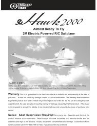
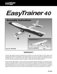
No. 4316 EXPO 3D Profile EP<br />
nWing Span: 31.5" (800mm) nLength: 32.17" (817mm) nWing Area: 252.3 sq.in. (16.28dm 2 )<br />
nWeight: 9.3 oz. (265g) nMotor: 370 with 6: 1 Gear nRadio: 4 CH, 3 Micro Servos Req'd<br />
No. 4317 G202 3D Profile EP<br />
nWing Span: 31.5"(800mm) nLength: 32.87 (835mm) nWing Area: 258.5 sq.in. (16.68dm 2 )<br />
nWeight: 9.3 oz. (265g) nMotor: 370 with 6: 1 Gear nRadio: 4 CH, 3 Micro Servos Req'd<br />
No. 4318 Christen Eagle 3D Profile EP<br />
nWing Span: 30.7"(780mm) nLength: 30.9" (785mm) nWing Area: 369.8 sq.in. (23.86dm 2 )<br />
nWeight: 10.5 oz. (300g) nMotor: 370 with 6:1 Gear nRadio: 4 CH, 3 Micro Servos Req'd<br />
Warranty:This kit is guaranteed to be free from defects in material and workmanship at the date of purchase.<br />
It does not cover any damage caused by use or modification. The warranty does not extend beyond the product<br />
itself and is limited only to the original cost of the kit. By the act of building this user-assembled kit, the user<br />
accepts all resulting liability for damage caused by the final product. If the buyer is not prepared to accept this<br />
liability, it can be returned new and unused to the place of purchase for a refund.<br />
Notice: Adult Supervision Required:This is not a toy. Assembly and flying of this product<br />
requires adult supervision. Read through this book completely and become familiar with the assembly and flight of<br />
this airplane. Inspect all parts for completeness and damage. Contact Thunder Tiger authorized agent if you find<br />
any problem or need tech support.
INTRODUCTION<br />
All of us at Thunder Tiger want to thank you for choosing the 3D Profile EP series.<br />
The 3D Profile EP series includes Expo 3D, G202 and Christen Eagle. These are the latest<br />
developments in small 3D aerobatic EP design and engineered to go together quickly and easily<br />
while still providing you with great looks and exceptional flying performance.<br />
The 3D Profile is good for those pilots who are interested in learning 3D-aerobatics or for those<br />
experienced 3D pilots looking for a relaxed practicing plane that can be used both outdoor or<br />
indoor.<br />
Thunder Tiger guarantees that you should enjoy the trouble free use from our R/C products.<br />
Thunder Tiger products have been sold worldwide through the authorized distributors that are<br />
supported directly and rapidly from Thunder Tiger. You may find that Thunder Tiger is always<br />
pursuing to explore new items creatively with highest quality. To update the latest product<br />
information and to get the best technical support, please fee free to contact your local hobby<br />
shops or Thunder Tiger authorized distributor.<br />
Table of Contents<br />
Introduction<br />
Pre-Assembly Notes...............................1<br />
Other Items Required.............................1<br />
Tools and Supplies Needed ...................1<br />
Part Drawings........................................2<br />
Assembly<br />
Wing........................................................4<br />
Tail...........................................................5<br />
Landing Gear..........................................6<br />
Servo.......................................................7<br />
Motor......................................................9<br />
RX, ESC, Battery.................................10<br />
Control Throws....................................10<br />
Balance ..............................................11<br />
3D Set Up<br />
Exponetial...........................................12<br />
Simulator.............................................12<br />
CG.......................................................12<br />
Flying..................................................13<br />
AMA Safety Code................................14
PRE-ASSEMBLY NOTES<br />
1.This manual is for 3D Profile EP series including<br />
Expo 3D, G202 and Christen Eagle. The photos<br />
shown in the assembly steps may not show all<br />
three kinds of plane as they are in the same manner<br />
of assembly. If you encounter any assembly<br />
question, you may contact Thunder Tiger authorized<br />
distributors or write email to Thunder Tiger directly<br />
for tech support.<br />
2.These 3D profile EP are for experienced R/C pilot<br />
orientated and not for novice or entry level pilot. If<br />
you are not an experienced pilot, please get a fully<br />
competent pilot to help you to learn. This will avoid<br />
potential damage of your model as this series are<br />
made of PSP board which is easily broken if heavy<br />
landing or crash.<br />
3.Please assemble your model exactly according to<br />
the instruction. Do not attempt to modify or change<br />
in any way as doing so may adversely change its<br />
flying characteristics.<br />
4.Before you begin please check the entire contents<br />
of this kit against the part drawing to be sure that no<br />
parts are missing or damaged. This will also help<br />
you to become familiar with each component of your<br />
plane. If you find any of parts are either missing or<br />
damaged. Please contact your dealer immediately<br />
for replacement.<br />
Note: Your dealer cannot accept kits for return if<br />
construction has begun.<br />
Other Items Required<br />
Radio: You will need at least a 4 channel radio<br />
control system with 3 sub-micro servos and mini<br />
receiver on an aircraft frequency for use in your 3D<br />
profiles EP.<br />
ESC: We recommend a quality Speed Controller for<br />
this plane like Ace ESC-10 is recommended.<br />
Lipoly Battery: Suggest to<br />
use Quality 2~3-cell Lipoly<br />
battery instead of any other NiCd<br />
or NiMH battery pack. The<br />
advantage of Lipoly battery is<br />
much lighter than the traditional<br />
Nicd or NiMH battery pack of the<br />
same capacity. Thunder Tiger<br />
provide high performance Ace<br />
Power Lipoly Battery which is at<br />
true discharge rate at 13C that<br />
most 3D pilots are looking for.<br />
The 2-cell Li-Poly battery is for normal flight yet 3-cell<br />
is good for 3D aerobatics.<br />
Lipoly Charger: You will need a performance Lipoly<br />
battery charger to charge your Lipoly battery either at<br />
flying field or home. Always pay high attention when<br />
you’re charging the Lipoly battery. Get a charger with<br />
alarm system and computerized charger with LCD<br />
screen that shows charging status. This will help you<br />
monitor the battery easily and safely.<br />
Extension Wire: You will need a short extension<br />
wire for aileron servo.<br />
Motor Care<br />
The included Super 370 motor is designed for 2~3-<br />
cells use yet we recommend you break-in the motor<br />
properly to extend the life of the motor. The following<br />
are some tricks :<br />
1. Drop some oil on both bushing at the end caps of motor.<br />
2. Break-in the motor for couple minutes at about 4.8 V<br />
without loading.<br />
3. Apply oil after every 5 flights for best performance.<br />
4. Do not fly continuously without letting motor have chance<br />
to cool down. This will hurt motor badly. Make sure<br />
motor is cool before you perform next flight.<br />
5. Motor Heat Sink will help cooling and you can get this<br />
heat sink at any hobby shop.<br />
OBL:Thunder Tiger OBL outrunner<br />
brushless motor 29 series is<br />
available for upgraded power. For<br />
more information please browse<br />
website at www.thundertiger.com<br />
No.2800 2cell 1050mAh<br />
No.2801 3cell 1050mAh<br />
No.8117AC<br />
No.8015AC<br />
No.8416 ACE Commander 4FD<br />
TOOLS AND SUPPLIES NEEDED<br />
Mixing Stick for Epoxy<br />
Rubbing Alcohol<br />
Paper Towels<br />
Hobby Knife<br />
Ruler<br />
Pen, Pencil or Maker<br />
Small Screw Drivers
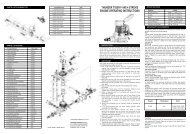
PART DRAWINGS<br />
Open the box and check that you have all the parts as shown below. If anything is missing please contact<br />
your dealer. Parts shown in this page are vary in foamy and linkeg sets of each kit.<br />
As6350 Foamy set expo 3D<br />
Horizontal Tail (1)<br />
Rudder (1)<br />
Main Wing (1)<br />
Triangle Balsa Wood (2)<br />
Tape (1)<br />
Double Side Tape (1)<br />
Velcro (1)<br />
Tail Skid (1) Wheel Pant (2)<br />
Square (2)<br />
Fuselage (1)<br />
As6351 Foamy set G202 3D<br />
Horizontal Tail (1)<br />
Rudder (1)<br />
Main Wing (1)<br />
Triangle Balsa Wood (2)<br />
Tape (1)<br />
Double Side Tape (1)<br />
Velcro (1)<br />
Tail Skid (1) Wheel Pant (2)<br />
Square (2)<br />
Fuselage (1)<br />
As6352 Foamy set Christen eagle 3D<br />
Upper Wing (1)<br />
Fuselage (1)<br />
Lower Wing (1)<br />
Double Side Tape (1)<br />
Horizontal Tail (1) Wing Support (2) Rudder (1)<br />
Velcro (1)<br />
Tail Skid (1) Wheel Pant (2) Square (2)<br />
Triangle Balsa Wood (2) Tape (1)<br />
As6359 linkage set (expo 3D, G202)<br />
As6363 linkage set (Christen eagle)<br />
Rudder Pushrod (1)<br />
Clevis (4)<br />
Rudder Pushrod (1)<br />
Aileron Linkage Rod (2)<br />
Elevator Pushrod (1) Aileron Pushrod (2) Elevator Pushrod (1) Aileron Pushrod (2)<br />
Clevis (4)
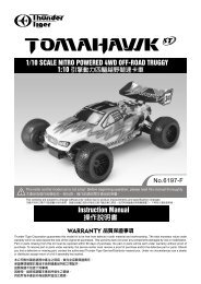
PART DRAWINGS<br />
Parts shown in this page are same for all 3D Profile EP planes.<br />
As6360 landing Gear<br />
As6355 Drive shaft<br />
Mount (1)<br />
Landing Gear (1)<br />
Spur Gear/Drive Shaft (1)<br />
2x5 mm<br />
Washer Screw (2)<br />
Retainer (2)<br />
Pinion (1)<br />
E Clip (1)<br />
No. 3549 11x 8 sF Propeller<br />
As6361 Decal<br />
Propeller (1)<br />
Decal (1)<br />
As6336 Wheel<br />
As6354 spinner<br />
Rubber Spinner (1)<br />
M3 Nut (2) Prop Washer (1)<br />
Wheel (2)<br />
As6358 Control Horn<br />
As6357 super 370 motor<br />
Motor (1)<br />
Control Horn (4) Back plate (4)<br />
As6356 motor mount<br />
3 x 5mm<br />
Machine Screw (2)<br />
Motor Mount (1)<br />
Mounting Strip (2) Washer (2)<br />
Bearing (2)<br />
2 x 8 mm<br />
Self-Tapping Screw (4)
Assembly / wing<br />
Assembly<br />
Expo 3D<br />
1. Check all pre-hinged aileron and elevator, lightly<br />
press the taped area and make sure the aileron<br />
and elevator will not come apart. You will also<br />
have to check this before and after each flight to<br />
get precise throws for better performance.<br />
G202<br />
Christen Eagle<br />
2. Cut triangle balsa wood as indicated length which<br />
is going to reinforce the main wing later and keep<br />
the rest wood for elevator.<br />
Expo 3D: 13.5cm; 6.5cm (5-1/4”, 2-1/2”)<br />
G202: 13cm; 8cm (5-1/8”, 3-1/8”)<br />
Christen Eagle: Lower Wing–1cm;9.5cm (3/8”, 3-3/4”)<br />
Upper Wing– 11cm (4-1/4”)<br />
4. Note the orientation of servo output shaft and<br />
install aileron servo on the wing first. Do not glue<br />
the wing before you install the aileron servo. Next<br />
connect the servo wire to RX and turn on radio to<br />
make sure the servo rotating direction is correct.<br />
Secure the servo horn with the screw which comes<br />
with the servo. Now you can center and epoxy the<br />
main wing in place. Reinforce wing with triangle<br />
Balsa wood. Note the servo wire should go right<br />
side as RX and ESC will be installed at right side<br />
of fuselage later.<br />
3. Get the furnished servo tape 3/16"x 1/2" (5x12mm)<br />
and place as shown.<br />
5. For Christen Eagle owner<br />
Locate wing support and epoxy the wing support and<br />
upper wing in place as shown.<br />
It will be easier if you place the airplane up side down<br />
to apply epoxy at the joints.
Assembly / tail<br />
Expo 3D<br />
8. Epoxy the tail in place. You may use the rest<br />
triangle balsa wood and epoxy it at the bottom of<br />
horizontal tail.<br />
G202<br />
Christen Eagle<br />
6. Use furnished square and make sure wing is<br />
perpendicular to the fuselage while gluing wing<br />
and fuselage together.<br />
9. Locate the tail skid, next use hobby knife to cut a<br />
slot at the bottom of fuselage tail. Then insert the<br />
tail skid in place.<br />
CUT<br />
Expo 3D<br />
G202<br />
7. For Expo 3D and G202, it is necessary to cut<br />
fuselage tail so the horizontal fin could go in.<br />
Christen Eagle<br />
10. Glue the tail skid in place as shown. For Expo 3D,<br />
you may need to cut one end of skid so it will not<br />
have any influence to rudder movement.
Assembly / landing gear<br />
Expo 3D<br />
12. Locate landing gear parts and wheels as shown.<br />
G202<br />
13. Secure the landing gear on plywood with furnished<br />
2 x 5mm washer wood screws.<br />
Expo 3D<br />
Christen Eagle<br />
G202<br />
11. Use the furnished tape to tape the Rudder in<br />
place. Tape the left side first then the right side.<br />
Christen Eagle<br />
14. Epoxy the landing gear assembly in the hollow<br />
square area.
Assembly / servo<br />
15. Install wheels by threading the wheel pant retainer<br />
in proper position.<br />
19. Install aileron control horns.<br />
16. Epoxy the wheel pants on the retainer. Make sure<br />
two wheel pants are parallel.<br />
20. Install aileron pushrods as shown.<br />
17. Install rudder control horn, slowly insert the control<br />
horn to avoid any damage of surface at the other<br />
side.<br />
21. For Christen Eagle owner, please install control<br />
horn on two wings for aileron linkage.<br />
Epoxy<br />
18. Press and lock the control<br />
horn by the backplate.<br />
Note the orientation of the<br />
backplate. Apply tiny of<br />
epoxy will help secure the contorl horn in place<br />
firmly.<br />
<br />
22. Locate aileron lingage rod and thread clevises on<br />
two ends. Snap the clevis on the lowest hole of the<br />
control horn for best control throw.
Assembly / servo<br />
Expo 3D<br />
23. Use the same way to install control horns for<br />
elevator and rudder.<br />
Expo 3D<br />
G202<br />
G202<br />
Christen Eagle<br />
24. Install rudder and elevator servo note the<br />
orientation of servo output shaft. Above photos<br />
shown are all at left side.<br />
Christen Eagle<br />
<br />
25. Install the elevator and rudder pushrods when<br />
servos are in neutral position and make sure<br />
rudder and elevator are even with the vertical fin<br />
and horizontal tail respectively.
Assembly / motor<br />
26. Locate all the parts of universal power unit.<br />
29. Secure power unit on the fuselage with the<br />
mounting plates by four 2x8mm self-tapping<br />
screws. Drive shaft should be in line with the<br />
fuselage without qny thrust angle.<br />
27. Press the bearings all the way in then insert the<br />
Spur Gear Drive Shaft. Snap on the E clip. Try<br />
pull the drive shaft and make sure E clip is well<br />
positioned and drive shaft will not come off.<br />
30. Locate M3 nut, put it in the propeller then thread<br />
the propeller on the drive shaft. Next attach<br />
propeller washer and another nut. Secure it firmly<br />
and make sure to leave at least 6mm drive shaft<br />
for rubber spinner.<br />
28. Install the motor in the power unit. To get good<br />
gear mesh, use a piece of thin paper and set<br />
between the pinion and spur gear. Then secure<br />
the motor tightly with 3x5mm machine screw and<br />
washer. Remove the paper by rotating the gear.<br />
31. Install the rubber spinner on drive shaft properly<br />
and make sure it is not transformed.
Assembly / rx, esc, battery<br />
Control Throws<br />
The following contorl throw of 3D Profile EP is merely<br />
a starting point for your radio setup and can be tailored<br />
to fit your flying syle.<br />
For All three models the aileron and elevator are of the<br />
same throws but rudder are different as shown below.<br />
Expo 3D & G202<br />
Aileron-Low Rate<br />
3/4"= 19mm<br />
3/4"= 19mm<br />
Aileron-High Rate<br />
1-1/4"= 32mm<br />
1-1/4"= 32mm<br />
Christen Eagle<br />
32. Connect the servo wires to receivers and speed<br />
controller as shown. You will need one servo<br />
extension to connect aileron servo. Use Velcro to<br />
secure battery as photo shown. Secure the RX<br />
and ESC with the furnished Double-Sided tape.<br />
Organize the wires and fix them on fuselage with<br />
tape if necessary.<br />
Elevator-Low Rate<br />
Elevator-High Rate<br />
Expo 3D<br />
Rudder-Low Rate<br />
1"= 25mm<br />
1"= 25mm<br />
1-1/2" = 38mm<br />
1-1/2" = 38mm<br />
1-3/4"= 44mm<br />
1-3/4"= 44mm<br />
Rudder-High Rate<br />
2 -1/2"= 64mm<br />
2 -1/2"= 64mm<br />
G202<br />
Rudder-Low Rate<br />
1-1/2" = 38mm<br />
1-1/2" = 38mm<br />
33. Route the antenna wire to the tail and tape it on<br />
fuselage.<br />
Rudder-High Rate<br />
2-1/4"=57mm<br />
2-1/4"=57mm<br />
Chrstin Eagle<br />
Rudder-Low Rate<br />
1-1/4"= 32mm<br />
1-1/4"= 32mm<br />
Rudder-High Rate<br />
1-3/4"= 44mm<br />
1-3/4"= 44mm<br />
10
Assembly / balance<br />
Balance<br />
It is important to balance the plane to get correct CG<br />
before you fly.<br />
Balance Point as indicated in each diagram.<br />
Expo 3D<br />
Longitude Balance<br />
C.G. Must be Set on Thrust Line<br />
3-1/4"~3-1/2" ( 8.5~9cm)<br />
3-1/4"~3-1/2" (( 8.5~9cm)<br />
C.G.<br />
C.G. C.G.<br />
G202<br />
3-3/4"~4" ( 9.5~10cm)<br />
3-3/4"~4" (( 9.5~10cm)<br />
C.G.<br />
C.G. C.G.<br />
C.G. is Too Low<br />
C.G. is Correct<br />
Christen Eagle<br />
3-1/2"~4" (9~10cm)<br />
3-1/2"~4" (9~10cm)<br />
C.G.<br />
C.G. C.G.<br />
As 3D planes do a lot of hovering so it is very<br />
important to do longitude balance to make hovering<br />
much more stable. Try to create a small hole after the<br />
motor and on the thrust line. Get music wire or string<br />
then thread the wire through the hole. Make sure that<br />
model hangs perfectly vertical as illustration. If not<br />
then try to adjust the location of battery, receiver or<br />
ESC to get good longitude balance.<br />
Congratulations<br />
Your done, may you have many successful flights<br />
filled with fun and lots of 3D maneuvers.<br />
Note: For the best flight performance of the Christen<br />
Eagle, a high center of gravity is important. Following<br />
the manual shown in Step 32 which shows the<br />
location of battery.<br />
Thank you for purchasing this 3D Profile EP from<br />
Thunder Tiger and we look forward to providing you<br />
with other great R/C products in the near future.<br />
11
Assembly / 3d setup<br />
Setting up for 3D flight<br />
Servo Output<br />
High Rate<br />
Low Rate<br />
Stick Travel<br />
1/3<br />
1/3 1/3<br />
Exponetial<br />
To make your 3D flight successful, the most<br />
important is to set up your radio properly and finetune<br />
the exponential. We would suggest you use<br />
a computerized radio plus a big LCD screen that<br />
could show the exponential graph as the illustration.<br />
Normally this computerized radio has dual rates or<br />
even triple rates. Once you fly it fine with low rate in<br />
normal flight, next you will have to set up 3D rate.<br />
We suggest the 3D-rate setting is same as lowrate<br />
setting around 1/3 of the total stick travel in the<br />
beginning. If you look at the graph, the middle section<br />
of 1/3 travel are most likely the same at low rate and<br />
3D high rate. Beyond this middle section the 3D rate<br />
setting is far higher than the low rate.<br />
SimulatorA good tool to practice 3D easier is to fly<br />
simulator. One may say simulator is not realistic but<br />
this is not true. There are some simulators available<br />
in the market and its scenery and performance are<br />
just like a real thing. For example, Aerofly Pro Deluxe<br />
USB version from Ikarus or Real Flight G3 from<br />
Greatplanes are all good simulators you can choose<br />
from.<br />
Simulator is a must buy tool if you seriously want to<br />
fly 3D aerobatics. There is no genius or born 3D pilot,<br />
remember that practice makes perfect. 30 minutes a<br />
day on a simulator can help you do hovering, torque<br />
roll easily as well as other aerobatics. If you would like<br />
to be a good 3D pilot, flying everyday is necessary.<br />
The reaction to control the airplane will be more<br />
nature. As there is no time to think when you do 3D<br />
aerobatics.<br />
Simulator practice might be perfect yet we suggest to<br />
do some actual flying as the supplemental so it will not<br />
go too far from the real thing as there are many things<br />
that you can not learn in the screen.<br />
12
Assembly / 3d setup<br />
CG<br />
Normally the correct CG position is beneficial to<br />
hovering flight. Actually, for 3D profiles its CG range<br />
is pretty large. Just give enough control surface<br />
movement, softened correctly with exponential throws<br />
then you may control the plane at a large range of CG<br />
positions. Why, it is because no airfoil of the plane.<br />
The only force to keep it in air is the thrust.<br />
Flying<br />
Even though you set up the airplane, it needs to be<br />
setup and fine-tuned in the air. Always start on low<br />
rates when launch the airplane or take off of the<br />
ground. Once you fine trim the airplane in the air then<br />
tune the exponential setting, you will be able to fly it all<br />
the time on the 3D rates.<br />
Once you got confidence to do hovering or do 3D<br />
aerobatics, we suggest you fly it near you. The closer<br />
the airplane, the better you can control the plane<br />
as you can see it very clear even if it has a slight<br />
movement. The other advantage is the lower or closer<br />
to ground, the less damage of the plane as it has less<br />
potential energy. It is useful for a dead battery or ESC<br />
cut off suddenly.<br />
13
2004 Official AMA National Model Aircraft Safety Code<br />
GENERAL<br />
1) I will not fly my model aircraft in sanctioned events,<br />
air shows or model flying demonstrations until it<br />
has been proven to be airworthy by having been<br />
previously, successfully flight tested.<br />
2) I will not fly my model higher than approximately<br />
400 feet within 3 miles of an airport without notifying<br />
the airport operator. I will give right-of-way and<br />
avoid flying in the proximity of full-scale aircraft.<br />
Where necessary, an observer shall be utilized to<br />
supervise flying to avoid having models fly in the<br />
proximity of full-scale aircraft.<br />
3) Where established, I will abide by the safety rules<br />
for the flying site I use, and I will not willfully and<br />
deliberately fly my models in a careless, reckless<br />
and/or dangerous manner.<br />
4) The maximum takeoff weight of a model is 55<br />
pounds, except models flown under Experimental<br />
Aircraft rules.<br />
5) I will not fly my model unless it is identified with my<br />
name and address or AMA number, on or in the<br />
model. (This does not apply to models while being<br />
flown indoors.)<br />
6) I will not operate models with metal-bladed<br />
propellers or with gaseous boosts, in which gases<br />
other than air enter their internal combustion<br />
engine(s); nor will I operate models with extremely<br />
hazardous fuels such as those containing<br />
tetranitromethane or hydrazine.<br />
RADIO CONTROL<br />
1) I will have completed a successful radio equipment<br />
ground range check before the first flight of a new<br />
or repaired model.<br />
2) I will not fly my model aircraft in the presence of<br />
spectators until I become a qualified flier, unless<br />
assisted by an experienced helper.<br />
3) At all flying sites a straight or curved line(s) must be<br />
established in front of which all flying takes place<br />
with the other side for spectators. Only personnel<br />
involved with flying the aircraft are allowed at or in<br />
the front of the flight line. Intentional flying behind<br />
the flight line is prohibited.<br />
4) I will operate my model using only radio control<br />
frequencies currently allowed by the Federal<br />
Communications Commission. (Only properly<br />
licensed Amateurs are authorized to operate<br />
equipment on Amateur Band frequencies.)<br />
5) Flying sites separated by three miles or more are<br />
considered safe from site-to site interference, even<br />
when both sites use the same frequencies. Any<br />
circumstances under three miles separation require<br />
a frequency management arrangement, which may<br />
be either an allocation of specific frequencies for<br />
each site or testing to determine that freedom from<br />
interference exists. Allocation plans or interference<br />
test reports shall be signed by the parties involved<br />
and provided to AMA Headquarters. Documents of<br />
agreement and reports may exist between<br />
(1) two or more AMA Chartered Clubs,<br />
(2) AMA clubs and individual AMA members not<br />
associated with AMA Clubs, or<br />
(3) two or more individual AMA members.<br />
6) For Combat, distance between combat engagement<br />
line and spectator line will be 500 feet per cubic<br />
inch of engine displacement. (Example: .40 engine<br />
= 200 feet.); electric motors will be based on<br />
equivalent combustion engine size. Additional safety<br />
requirements will be per the RC Combat section of<br />
the current Competition Regulations.<br />
7) At air shows or model flying demonstrations, a<br />
single straight line must be established, one side of<br />
which is for flying, with the other side for spectators.<br />
8) With the exception of events flown under AMA<br />
Competition rules, after launch, except for pilots<br />
or helpers being used, no powered model may be<br />
flown closer than 25 feet to any person.<br />
9) Under no circumstances may a pilot or other person<br />
touch a powered model in flight.<br />
THUNDER TIGER CORPORATION http://www.thundertiger.com<br />
JE6695