herrenknecht ag softground tbms > 40 ft - SCATnow
herrenknecht ag softground tbms > 40 ft - SCATnow
herrenknecht ag softground tbms > 40 ft - SCATnow

Create successful ePaper yourself
Turn your PDF publications into a flip-book with our unique Google optimized e-Paper software.
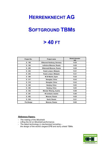
HERRENKNECHT AG<br />
SOFTGROUND TBMS<br />
><strong>40</strong> FT<br />
Project No. Project name Shield diameter<br />
[m]<br />
S - 108 Elbtunnel Hamburg, Germany 14.20<br />
S - 164 Lefortovo Moscow, Russia 14.20<br />
S - 250 Silberwald Moscow, Russia 14.20<br />
S - 252 Kuala Lumpur, Malaysia 13.21<br />
S - 253 Kuala Lumpur, Malaysia 13.21<br />
S - 300 M-30 Madrid, Spain 15.20<br />
S - 317 Shanghai, China 15.43<br />
S - 318 Shanghai, China 15.43<br />
S - 349 Nanjing, China 14.93<br />
S - 350 Nanjing, China 14.93<br />
S - 352 Münster Wiesing, Austria 13.00<br />
S - 381 H8 Jenbach, Austria 13.00<br />
S - 483 Moscow, Russia 14.20<br />
S - 534 Sochi, Russia 13.21<br />
Pre-Design Moscow, Russia 19.00<br />
Reference Papers:<br />
- The making of the Mixshield.<br />
- Li<strong>ft</strong>ing the lid on Mixshield performance.<br />
- The latest technology in mechanized tunneling –<br />
the design of the world’s largest EPB and slurry shield TBMs.
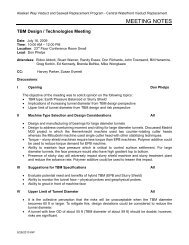
HERRENKNECHT | TRAFFIC TUNNELLING<br />
SALES.NET<br />
PROJECT DATASHEET. Updated: 5/15/2008<br />
S-Number:<br />
Name:<br />
Location:<br />
Country:<br />
S-108<br />
4. Röhre Elbtunnel Hamburg<br />
Hamburg<br />
Germany<br />
.<br />
MAIN GEOLOGY CONTRACT TBM SPEC. TBM PROGRESS BACKGROUND .<br />
.<br />
S-Number: S-108 .<br />
Project Name: 4. Röhre Elbtunnel Hamburg .<br />
Location: Hamburg .<br />
Country: Germany .<br />
Sales Region: Europe .<br />
Diameter: 14200 mm .<br />
Total Tunnel Length: 2560 m .<br />
Machine Type: Mixshield .<br />
Employment: Road .<br />
Project Status: Finished .<br />
. . .<br />
.<br />
MAIN GEOLOGY CONTRACT TBM SPEC. TBM PROGRESS BACKGROUND .<br />
.<br />
Max. Op. Pressure:<br />
5.5 bar<br />
Geology:<br />
Sand, boulder clay, silt and gravel, erratic blocks<br />
.<br />
.<br />
1
HERRENKNECHT | TRAFFIC TUNNELLING<br />
SALES.NET<br />
PROJECT DATASHEET. Updated: 5/15/2008<br />
S-Number:<br />
Name:<br />
Location:<br />
Country:<br />
S-164<br />
Lefortovo<br />
Moscow<br />
Russia<br />
.<br />
MAIN GEOLOGY CONTRACT TBM SPEC. TBM PROGRESS BACKGROUND .<br />
.<br />
S-Number: S-164 .<br />
Project Name: Lefortovo .<br />
Location: Moscow .<br />
Country: Russia .<br />
Sales Region: Europe .<br />
Diameter: 14200 mm .<br />
Total Tunnel Length: 4112 m .<br />
Machine Type: Mixshield .<br />
Employment: Road .<br />
Project Status: Finished .<br />
. . .<br />
.<br />
MAIN GEOLOGY CONTRACT TBM SPEC. TBM PROGRESS BACKGROUND .<br />
.<br />
Min. Overburden:<br />
7 m<br />
Max. Overburden:<br />
30 m<br />
Geology:<br />
Fine to coarse sand, clay, limestone (medium strength, partially very fissured)<br />
.<br />
.<br />
1
HERRENKNECHT | TRAFFIC TUNNELLING<br />
SALES.NET<br />
PROJECT DATASHEET. Updated: 5/15/2008<br />
S-Number:<br />
Name:<br />
Location:<br />
Country:<br />
S-250<br />
Silberwald<br />
Moscow<br />
Russia<br />
.<br />
MAIN GEOLOGY CONTRACT TBM SPEC. TBM PROGRESS BACKGROUND .<br />
.<br />
S-Number: S-250 .<br />
Project Name: Silberwald .<br />
Location: Moscow .<br />
Country: Russia .<br />
Sales Region: Europe .<br />
Diameter: 14200 mm .<br />
Total Tunnel Length: 3010 m .<br />
Machine Type: Mixshield .<br />
Employment: Road .<br />
Project Status: Finished .<br />
. . .<br />
.<br />
MAIN GEOLOGY CONTRACT TBM SPEC. TBM PROGRESS BACKGROUND .<br />
.<br />
Max. Overburden:<br />
30 m<br />
Geology:<br />
Sand, clay, rock<br />
.<br />
.<br />
1
HERRENKNECHT | TRAFFIC TUNNELLING<br />
SALES.NET<br />
PROJECT DATASHEET. Updated: 11/12/2008<br />
S-Number:<br />
Name:<br />
Location:<br />
Country:<br />
S-252<br />
Stormwater Man<strong>ag</strong>ement and Road Tunnel (SMART)<br />
Kuala Lumpur<br />
Malaysia<br />
.<br />
MAIN GEOLOGY CONTRACT TBM SPEC. TBM PROGRESS BACKGROUND .<br />
.<br />
S-Number: S-252 .<br />
Project Name:<br />
Stormwater Man<strong>ag</strong>ement and<br />
Road Tunnel (SMART)<br />
.<br />
Lot: North Drive .<br />
Location: Kuala Lumpur .<br />
Country: Malaysia .<br />
Sales Region: Asia Pacific .<br />
Diameter: 13210 mm .<br />
Total Tunnel Length: 5<strong>40</strong>0 m .<br />
Machine Type: Mixshield .<br />
Employment: Road .<br />
Project Status: Finished .<br />
. . .<br />
.<br />
MAIN GEOLOGY CONTRACT TBM SPEC. TBM PROGRESS BACKGROUND .<br />
.<br />
Min. Overburden:<br />
10 m<br />
Max. Overburden:<br />
20 m<br />
Max. Op. Pressure:<br />
5 bar<br />
Geology:<br />
Limestone, marble, sand<br />
.<br />
.<br />
1
HERRENKNECHT | TRAFFIC TUNNELLING<br />
SALES.NET<br />
PROJECT DATASHEET. Updated: 11/14/2008<br />
S-Number:<br />
Name:<br />
Location:<br />
Country:<br />
S-253<br />
Stormwater Man<strong>ag</strong>ement and Road Tunnel (SMART)<br />
Kuala Lumpur<br />
Malaysia<br />
.<br />
MAIN GEOLOGY CONTRACT TBM SPEC. TBM PROGRESS BACKGROUND .<br />
.<br />
S-Number: S-253 .<br />
Project Name:<br />
Stormwater Man<strong>ag</strong>ement and<br />
Road Tunnel (SMART)<br />
.<br />
Lot: South Drive .<br />
Location: Kuala Lumpur .<br />
Country: Malaysia .<br />
Sales Region: Asia Pacific .<br />
Diameter: 13210 mm .<br />
Total Tunnel Length: 3944 m .<br />
Machine Type: Mixshield .<br />
Employment: Road .<br />
Project Status: Finished .<br />
. . .<br />
.<br />
MAIN GEOLOGY CONTRACT TBM SPEC. TBM PROGRESS BACKGROUND .<br />
.<br />
Min. Overburden:<br />
10 m<br />
Max. Overburden:<br />
20 m<br />
Max. Op. Pressure:<br />
5 bar<br />
Geology:<br />
Limestone, sand, marble<br />
.<br />
.<br />
1
HERRENKNECHT | TRAFFIC TUNNELLING<br />
SALES.NET<br />
PROJECT DATASHEET. Updated: 12/12/2008<br />
S-Number:<br />
Name:<br />
Location:<br />
Country:<br />
S-300<br />
Madrid M-30 By-Pass Sur Túnel Norte<br />
Madrid<br />
Spain<br />
.<br />
MAIN GEOLOGY CONTRACT TBM SPEC. TBM PROGRESS BACKGROUND .<br />
.<br />
S-Number: S-300 .<br />
Project Name:<br />
Madrid M-30 By-Pass Sur Túnel<br />
Norte<br />
.<br />
Lot: Calle 30 .<br />
Location: Madrid .<br />
Country: Spain .<br />
Sales Region: Europe .<br />
Diameter: 15200 mm .<br />
Total Tunnel Length: 3526 m .<br />
Machine Type: EPB Shield .<br />
Employment: Road .<br />
Project Status: Finished .<br />
. . .<br />
.<br />
MAIN GEOLOGY CONTRACT TBM SPEC. TBM PROGRESS BACKGROUND .<br />
.<br />
Min. Overburden:<br />
12 m<br />
Max. Overburden:<br />
67 m<br />
Max. Op. Pressure:<br />
6 bar<br />
Geology:<br />
Peñuela, Peñuela + gypsum, massive gypsum<br />
.<br />
.<br />
1
HERRENKNECHT | TRAFFIC TUNNELLING<br />
SALES.NET<br />
PROJECT DATASHEET. Updated: 11/12/2008<br />
S-Number:<br />
Name:<br />
Location:<br />
Country:<br />
S-318<br />
Shanghai Changjiang Under River Tunnel Project<br />
Shanghai<br />
China<br />
.<br />
MAIN GEOLOGY CONTRACT TBM SPEC. TBM PROGRESS BACKGROUND .<br />
.<br />
S-Number: S-318 .<br />
Project Name:<br />
Shanghai Changjiang Under<br />
River Tunnel Project<br />
.<br />
Lot: Chongming .<br />
Location: Shanghai .<br />
Country: China .<br />
Sales Region: Asia Pacific .<br />
Diameter: 15430 mm .<br />
Total Tunnel Length: 7472 m .<br />
Machine Type: Mixshield .<br />
Employment: Road .<br />
Project Status: Finished .<br />
. . .<br />
.<br />
MAIN GEOLOGY CONTRACT TBM SPEC. TBM PROGRESS BACKGROUND .<br />
.<br />
Min. Overburden:<br />
20 m<br />
Max. Overburden:<br />
23 m<br />
Max. Op. Pressure:<br />
6 bar<br />
Geology:<br />
Sand, clay, rubble<br />
.<br />
.<br />
1
HERRENKNECHT | TRAFFIC TUNNELLING<br />
SALES.NET<br />
PROJECT DATASHEET. Updated: 9/4/2008<br />
S-Number:<br />
Name:<br />
Location:<br />
Country:<br />
S-317<br />
Shanghai Changjiang Under River Tunnel Project<br />
Shanghai<br />
China<br />
.<br />
MAIN GEOLOGY CONTRACT TBM SPEC. TBM PROGRESS BACKGROUND .<br />
.<br />
S-Number: S-317 .<br />
Project Name:<br />
Shanghai Changjiang Under<br />
River Tunnel Project<br />
.<br />
Lot: Chongming .<br />
Location: Shanghai .<br />
Country: China .<br />
Sales Region: Asia Pacific .<br />
Diameter: 15430 mm .<br />
Total Tunnel Length: 7472 m .<br />
Machine Type: Mixshield .<br />
Employment: Road .<br />
Project Status: Finished .<br />
. . .<br />
.<br />
MAIN GEOLOGY CONTRACT TBM SPEC. TBM PROGRESS BACKGROUND .<br />
.<br />
Min. Overburden:<br />
20 m<br />
Max. Overburden:<br />
23 m<br />
Max. Op. Pressure:<br />
6 bar<br />
Geology:<br />
Sand, clay, rubble<br />
.<br />
.<br />
1
HERRENKNECHT | TRAFFIC TUNNELLING<br />
SALES.NET<br />
PROJECT DATASHEET. Updated: 12/3/2008<br />
S-Number:<br />
Name:<br />
Location:<br />
Country:<br />
S-349<br />
Nanjing<br />
Nanjing<br />
China<br />
.<br />
MAIN GEOLOGY CONTRACT TBM SPEC. TBM PROGRESS BACKGROUND .<br />
.<br />
S-Number: S-349 .<br />
Project Name: Nanjing .<br />
Lot: Right Tunnel .<br />
Location: Nanjing .<br />
Country: China .<br />
Sales Region: Asia Pacific .<br />
Diameter: 14930 mm .<br />
Total Tunnel Length: 2933 m .<br />
Machine Type: Mixshield .<br />
Employment: Road .<br />
Project Status: Tunnelling .<br />
. . .<br />
.<br />
MAIN GEOLOGY CONTRACT TBM SPEC. TBM PROGRESS BACKGROUND .<br />
.<br />
Min. Overburden:<br />
6 m<br />
Max. Overburden:<br />
30 m<br />
Max. Op. Pressure:<br />
7.5 bar<br />
Geology:<br />
Silt, sand, clay, gravel<br />
.<br />
.<br />
1
HERRENKNECHT | TRAFFIC TUNNELLING<br />
SALES.NET<br />
PROJECT DATASHEET. Updated: 12/3/2008<br />
S-Number:<br />
Name:<br />
Location:<br />
Country:<br />
S-350<br />
Nanjing<br />
Nanjing<br />
China<br />
.<br />
MAIN GEOLOGY CONTRACT TBM SPEC. TBM PROGRESS BACKGROUND .<br />
.<br />
S-Number: S-350 .<br />
Project Name: Nanjing .<br />
Lot: Le<strong>ft</strong> Tunnel .<br />
Location: Nanjing .<br />
Country: China .<br />
Sales Region: Asia Pacific .<br />
Diameter: 14930 mm .<br />
Total Tunnel Length: 2933 m .<br />
Machine Type: Mixshield .<br />
Employment: Road .<br />
Project Status: Tunnelling .<br />
. . .<br />
.<br />
MAIN GEOLOGY CONTRACT TBM SPEC. TBM PROGRESS BACKGROUND .<br />
.<br />
Min. Overburden:<br />
6 m<br />
Max. Overburden:<br />
30 m<br />
Max. Op. Pressure:<br />
7.5 bar<br />
Geology:<br />
Silt, sand, clay, gravel<br />
.<br />
.<br />
1
HERRENKNECHT | TRAFFIC TUNNELLING<br />
SALES.NET<br />
PROJECT DATASHEET. Updated: 12/3/2008<br />
S-Number:<br />
Name:<br />
Location:<br />
Country:<br />
S-352<br />
Inntalquerung<br />
Münster<br />
Austria<br />
.<br />
MAIN GEOLOGY CONTRACT TBM SPEC. TBM PROGRESS BACKGROUND .<br />
.<br />
S-Number: S-352 .<br />
Project Name: Inntalquerung .<br />
Lot: H 3-4 Münster Wiesing .<br />
Location: Münster .<br />
Country: Austria .<br />
Sales Region: Europe .<br />
Diameter: 13000 mm .<br />
Total Tunnel Length: 58<strong>40</strong> m .<br />
Machine Type: Mixshield .<br />
Employment: Railway .<br />
Project Status: Tunnelling .<br />
. . .<br />
.<br />
MAIN GEOLOGY CONTRACT TBM SPEC. TBM PROGRESS BACKGROUND .<br />
.<br />
Min. Overburden:<br />
13 m<br />
Max. Overburden:<br />
44 m<br />
Max. Op. Pressure:<br />
5 bar<br />
Geology:<br />
Pebble stones, sand, coarse clay, brash, gravel<br />
.<br />
.<br />
1
HERRENKNECHT | TRAFFIC TUNNELLING<br />
SALES.NET<br />
PROJECT DATASHEET. Updated: 12/3/2008<br />
S-Number:<br />
Name:<br />
Location:<br />
Country:<br />
S-381<br />
Inntalquerung<br />
Jenbach<br />
Austria<br />
.<br />
MAIN GEOLOGY CONTRACT TBM SPEC. TBM PROGRESS BACKGROUND .<br />
.<br />
S-Number: S-381 .<br />
Project Name: Inntalquerung .<br />
Lot: H8 Jenbach .<br />
Location: Jenbach .<br />
Country: Austria .<br />
Sales Region: Europe .<br />
Diameter: 13000 mm .<br />
Total Tunnel Length: 3470 m .<br />
Machine Type: Mixshield .<br />
Employment: Railway .<br />
Project Status: Tunnelling .<br />
. . .<br />
.<br />
MAIN GEOLOGY CONTRACT TBM SPEC. TBM PROGRESS BACKGROUND .<br />
.<br />
Min. Overburden:<br />
5 m<br />
Max. Overburden:<br />
24 m<br />
Max. Op. Pressure:<br />
5 bar<br />
Geology:<br />
Components of bunter, alternating sequence of gravel with sand and silt,<br />
sandy to silty gravel with stones<br />
.<br />
.<br />
1
HERRENKNECHT | TRAFFIC TUNNELLING<br />
SALES.NET<br />
PROJECT DATASHEET. Updated: 11/26/2008<br />
S-Number:<br />
Name:<br />
Location:<br />
Country:<br />
S-483<br />
Zaryzino Südtangente Moskau<br />
Moscow<br />
Russia<br />
.<br />
MAIN GEOLOGY CONTRACT TBM SPEC. TBM PROGRESS BACKGROUND .<br />
.<br />
S-Number: S-483<br />
Project Name:<br />
Zaryzino Südtangente Moskau<br />
Location:<br />
Moscow<br />
Country:<br />
Russia<br />
Sales Region:<br />
Europe<br />
Diameter:<br />
14200 mm<br />
Total Tunnel Length:<br />
2<strong>40</strong>0 m<br />
Machine Type:<br />
Mixshield<br />
Employment:<br />
Road<br />
Project Status:<br />
Refurbishment<br />
.<br />
.<br />
MAIN GEOLOGY CONTRACT TBM SPEC. TBM PROGRESS BACKGROUND .<br />
.<br />
Geology:<br />
Sand, loam, limestone<br />
.<br />
.<br />
1
HERRENKNECHT | TRAFFIC TUNNELLING<br />
SALES.NET<br />
PROJECT DATASHEET. Updated: 12/19/2008<br />
S-Number:<br />
Name:<br />
Location:<br />
Country:<br />
S-534<br />
Sotschi Straßentunnel Nr.3<br />
Sochi<br />
Russia<br />
.<br />
MAIN GEOLOGY CONTRACT TBM SPEC. TBM PROGRESS BACKGROUND .<br />
.<br />
S-Number: S-534<br />
Project Name:<br />
Sotschi Straßentunnel Nr.3<br />
Lot:<br />
Adler - Krasnaja Poljana<br />
Location:<br />
Sochi<br />
Country:<br />
Russia<br />
Sales Region:<br />
Europe<br />
Diameter:<br />
13210 mm<br />
Total Tunnel Length:<br />
4200 m<br />
Machine Type:<br />
Single Shield TBM<br />
Employment:<br />
Road<br />
Project Status:<br />
Contract<br />
.<br />
.<br />
MAIN GEOLOGY CONTRACT TBM SPEC. TBM PROGRESS BACKGROUND .<br />
.<br />
Geology:<br />
Limestone<br />
.<br />
.<br />
1
H E R R E N K N E C H T A G | U T I L I T Y T U N N E L L I N G | T R A F F I C T U N N E L L I N G<br />
Moscow, Mix Shield Ø19m – Basic Design<br />
Technical Data TBM:<br />
Type: Mix Shield<br />
Diameter Ø 19 m<br />
Total Length 85 m<br />
Total Weight 5.500 t<br />
Shield Thrust 3<strong>40</strong>.000 KN<br />
Max Pressure 6 bar<br />
Installed Power 14,0 W<br />
Tunnel: Segmental lining, watertight<br />
Type: 4 lane road + light rail<br />
Segment OD: 18,45 m<br />
Segment ID: 16,85 m<br />
Segment length: 2,0 m
REFERENCE PAPER:<br />
THE MAKING OF THE MIXSHIELD.
MIXSHIELDS<br />
The making of the<br />
Mixshield – Part 1<br />
In the first of a two-part series, Werner Burger, head of design and<br />
engineering, and Gerhard Wehrmeyer, director of traffic tunnelling, for<br />
Herrenknecht AG, examine the development of the modern Mixshield<br />
Since its initial introduction, in 1985,<br />
the Mixshield TBM has taken on<br />
an essential role within the world<br />
of mechanical tunnel excavation.<br />
With its ability to operate as a classic slurryshield,<br />
or change to Open or Earth Pressure<br />
Balance (EPB) mode mid-drive, the<br />
Mixshield offers a unique concept for dealing<br />
with mixed ground excavation conditions.<br />
In order to appreciate how these<br />
machines have evolved, this article looks at<br />
the history and development of Mixshield<br />
technology over recent decades and the<br />
impact this has had on the underground<br />
construction industry.<br />
even today, the term “Mixshield” is still used<br />
for “slurry only” machines as well as for<br />
convertible shields. In all cases, however, the<br />
use of a submerged wall/pressure bulkhead<br />
combination, to create an air bubble for face<br />
pressure control, has remained an essential<br />
design feature for this type of machine.<br />
Right & below: Fig 1 - The HERA Mixshield<br />
Cutting<br />
wheel<br />
Submerged<br />
wall<br />
Shield<br />
skin<br />
Air lock Shield tail seal Segment<br />
Push<br />
transport<br />
cylinder Erector<br />
Development of technology<br />
The first European attempts to develop a<br />
bentonite shield began in England in the<br />
early 1960s, leading to the excavation of a<br />
short experimental tunnel in London, in<br />
1971. German contractor Wayss & Freyt<strong>ag</strong><br />
took these initial ideas and built upon them,<br />
incorporating an air bubble principle to<br />
control and regulate face support pressure.<br />
These early machines were mainly used in<br />
gravel and sand under lower water pressure,<br />
such as the Wilhelmsburg CSO tunnel, in<br />
Germany, which was completed in 1974.<br />
The shields were equipped with a centre<br />
sha<strong>ft</strong> drive and light spoke-type cutterheads<br />
with square dr<strong>ag</strong> tools, reflecting their limited<br />
range of application at that st<strong>ag</strong>e.<br />
With a view to finding an alternative to<br />
conventional compressed air excavations,<br />
which were common at the time, Wayss &<br />
Freyt<strong>ag</strong> concentrated on the design of face<br />
support systems and the development of a<br />
tail shield seal that would stand up to the<br />
rough conditions of mechanical excavation.<br />
In parallel with these developments, the<br />
evolution of water-resistant single-shell<br />
concrete segmental linings occurred.<br />
Early Mixshield concepts focused both on<br />
the development of a shield that would<br />
provide a slurry supported tunnel face and<br />
also an open shield that could enable a<br />
change of operational mode [1] . That is why,<br />
Grill<br />
Front<br />
section<br />
Articulation<br />
cylinder<br />
Middle<br />
section<br />
Coupling<br />
joint<br />
Shield<br />
tail<br />
The Mixshield is ultimately distinguished<br />
by the following features:<br />
• A modular design that allows adaption to<br />
different modes of operation (slurry, open,<br />
and EPB) for different projects, or a fullyequipped<br />
machine for changes mid-drive<br />
• Centre-free cutterhead drive with threeaxis<br />
roller bearing for a centrally arranged<br />
muck transportation system (screw or belt)<br />
• Centre-free cutterhead drive to<br />
accommodate various media (water,<br />
bentonite, hydraulics, electrics, etc) into<br />
the cutterhead and excavation chamber<br />
via a rotary joint<br />
• Integration of a cutterhead support system<br />
with axial and radial articulation by means<br />
of a spherical bearing<br />
Return line<br />
Feed line<br />
First trailer<br />
The first application of a true Mixshield<br />
machine was at the HERA tunnel, in<br />
Hamburg, in 1985. This 6.2km-long project<br />
accomplished advance rates of up to<br />
20m/day. The developments introduced<br />
proved successful, following a few<br />
adaptations during tunnelling, and confirmed<br />
the suitability of the new design.<br />
Like other early Mixshields, the HERA<br />
machine had a cutterhead that tilted forward<br />
at 3°. The idea was that a slightly inclined<br />
face would help with face stability. However,<br />
with growing experience and confidence in<br />
the principle of a bentonite-supported face,<br />
this mechanically cumbersome configuration<br />
eventually disappeared in favour of vertically<br />
mounted cutterheads.<br />
MAY 2008 Tunnels & Tunnelling International 35
MIXSHIELDS<br />
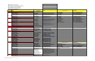
Year Project Development<br />
Table 1: Developments in Mixshield technology<br />
1985 S-12 HERA • Mixshield: Centre free cutterhead drive<br />
Passive shield articulation joint<br />
Grouting through tail shield with external grout lines<br />
1987 S-21 Lille • Main bearing as three axis roller bearing<br />
• Centre flushing<br />
• Single lip tail seal type S1<br />
• Double erector with semi-automatic mechanical gripping<br />
1988 S-41 Nuremberg • Fully-articulated cutterhead with spherical bearing<br />
• Cutterhead with mixed face tool arrangement including disc cutters<br />
• Grouting through tail shield<br />
1988 S-47 Duisburg TA 6 • Jaw type rock crusher in invert (initially without grill in front of suction pipe - added later)<br />
1989 S-50 Grauholz • Mixshield as convertible shield: Changing operation mode slurry – open<br />
• Large diameter > 11m<br />
• Operating pressure 4bar<br />
• Cutterhead flushing<br />
• Fixed centre plate cutterhead drive with inner seal system<br />
• Compensation pipes excavation chamber – pressure chamber<br />
• Vacuum erector<br />
• Invert fill within backup area<br />
• Data recording<br />
1989 S-52 Mülheim BA 8 • Hard rock cutterhead with disc cutters in pressurised slurry<br />
• Articulated suction pipe<br />
• Slurry supply in front of submerged wall<br />
• Hard rock TBM: Thrust cylinder skew controlled<br />
Hydraulic wing type stabilisers<br />
17” backloading cutters only<br />
Bolt-on bucket lips<br />
1991 S-67 Strasbourg • Closed cutterhead with back loading scrapers<br />
• Hydraulically extendable gauge cutter<br />
• Agitator wheels in front of suction pipe<br />
• Re-circulation system to increase slurry flow within excavation chamber<br />
• Initial application of wire brush tail seals on a Mixshield<br />
• Segment supply in invert area<br />
• Automatic “weekend control” for slurry suspension supply<br />
1992 S-68 Essen Lot 34 • Active centre cutter with independent slurry feed and suction lines<br />
• Extendable face plates<br />
• Submerged wall front gate<br />
1992 S-71 Köln Los M1 • Floating thrust cylinders with hydraulic clamping system<br />
1994 S-85 Duisburg TA 7/8 • Conversion of operating modes slurry – EPB via exchange of invert shield segment in sha<strong>ft</strong><br />
• Drill tubes through skin for pre-excavation grouting and probing<br />
• Open cutterhead centre with independent slurry feed and suction line<br />
1996 S-103 Sydney • Rotary crusher / sizer<br />
• Unidirectional mixed face cutterhead<br />
1997 S-108 4 Elbröhre • Accessible cutterhead for atmospheric cutter tool change<br />
• Face pressure 5.5 bar<br />
• World largest shield diameter: 14.2m<br />
• Preparation for diving activities<br />
• Hyperbaric rescue shuttle<br />
• Support pressure control to match tidal changes<br />
1998 S-127 Socatop • Conversion of operating modes slurry – EPB in tunnel<br />
1999 S-137 Westerschelde • Initial use of saturation diving up to 7.5 bar<br />
• Long-distance tunnelling with permanent face pressure >4 bar<br />
• Initial use of hyperbaric transfer shuttle and living chamber<br />
1999 S-150 Sophia • Continuous mining in so<strong>ft</strong> ground with positive face support<br />
2000 S-152 Wesertunnel • Closed invert segment<br />
2005 S-246 Hallandsås • 13 bar max operational pressure<br />
• Convertible TBM with fines handling flushing circuit in open mode<br />
2006 S-317/318 Chongming • World’s largest shield diameter: 15.43m<br />
• Improved cutterhead access for atmospheric cutter tool change<br />
36 Tunnels & Tunnelling International MAY 2008
MIXSHIELDS<br />
Another obvious design feature on early<br />
machines was the wide open, light cutting<br />
wheel design and a large submerged wall<br />
opening. It was thought that these were<br />
essential requirements to ensure the best<br />
possible bentonite circulation and therefore<br />
stability of the face. As with the inclined face,<br />
however, it became obvious these were not<br />
mandatory requirements and that cutterhead<br />
designs more appropriate to mixed face<br />
conditions could be employed without<br />
negative effects on face stability or<br />
settlement. The difference in layout between<br />
slurry shields and EPB cutterheads therefore<br />
started to disappear [2] . Today’s cutterhead<br />
designs are driven by a much wider range of<br />
factors – including wear protection, muck<br />
flow, tool arrangement and tool access.<br />
In the late 1980s, the potential of Mixshield<br />
machines became obvious to the tunnelling<br />
community. For the next 15 years, projects<br />
and orders were heavily influenced by the<br />
market enthusiastically embracing the<br />
concept. The development of other so<strong>ft</strong><br />
ground technology, such as compressed air<br />
shields and the membrane shield, were all<br />
but abandoned in favour of the Mixshield;<br />
which had already enabled the completion of<br />
projects previously considered impossible.<br />
From a technical point of view, the stepby-step<br />
development of the Mixshield (Table<br />
1) reads like a technical requirement<br />
catalogue for today’s slurry shields. The only<br />
difference being that the initial introduction of<br />
any new feature on a given project required a<br />
huge amount of dedication and commitment<br />
from all parties throughout the learning curve.<br />
Early milestones included the application<br />
of a Mixshield, used as a slurry machine, in<br />
Duisburg, which adopted a jaw crusher for<br />
boulders up to 500mm; the use of a hard<br />
rock cutterhead in Mülheim; convertible<br />
operation modes (closed mode with slurry<br />
circuit – open mode with centre belt<br />
conveyor discharge system) for the Grauholz<br />
tunnel; and Mixshield operation in Strasbourg<br />
with slurry support and closed cutterhead in<br />
coarse sand and gravel.<br />
Additional progress was made in the mid-<br />
1990s with projects such as the fourth Elbe<br />
tunnel and the Westerschelde crossing.<br />
Since then, advances to larger diameters,<br />
higher water pressures and shallower cover<br />
have presented a whole new dimension of<br />
challenges. Many engineering questions,<br />
such as lowering the bentonite level for face<br />
access, had to be revisited and new<br />
innovative solutions such as accessible<br />
cutterheads for cutter tool changes under<br />
atmospheric conditions were created.<br />
As well as direct improvements to<br />
Mixshield technology, several more general<br />
TBM developments have also contributed to<br />
the advancement of Mixshields, including:<br />
• Articulated cutterheads to allow<br />
overcutting and full control of cutterhead<br />
and main bearing loads<br />
• Floating thrust cylinder systems to address<br />
increased segment length and difficult<br />
tunnel alignments<br />
• Mixed and variable face cutterhead and<br />
backloading tool designs<br />
• High-pressure mainbearing, articulation<br />
and tailseal concepts<br />
• Vacuum systems for segment erection<br />
• Advanced systems for data recording and<br />
processing or process automation<br />
Many of these more general developments<br />
have to be viewed in combination with<br />
related advancements, e.g. segment design<br />
and manufacturing, soil conditioning, sealant<br />
materials, alignment control and survey<br />
systems, IT systems and data transfer.<br />
In addition to the coventional use of<br />
Mixshields for face support in so<strong>ft</strong> ground,<br />
the growing use of closed mode operation in<br />
rock tunnels has also been seen in recent<br />
years. In water bearing rock with the potential<br />
for high water inflows and/or pressure, the<br />
control of water inflow through the<br />
cutterhead is essential for operational<br />
reasons (segment backfill grouting, muck<br />
discharge) and, in many cases, even more so<br />
for environmental reasons.<br />
The traditional approach to such ground<br />
conditions is pre-excavation grouting from<br />
within the shield ahead of the tunnel face.<br />
Depending on rock conditions, pre-grouting<br />
activities can be time-consuming and do not<br />
always guarantee success, especially <strong>ag</strong>ainst<br />
flowing water. To overcome these problems,<br />
a closeable single shield rock machine was<br />
developed that would allow pre-excavation<br />
grouting using preventer systems <strong>ag</strong>ainst<br />
static water pressure. The next logical step<br />
was to install an additional slurry circuit muck<br />
transport system to deal with worst-case<br />
scenarios in closed mode.<br />
Operational modes for such hard rock<br />
Mixshields include: a) Open mode with dry<br />
primary muck discharge system (e.g.<br />
conveyor); b) Open mode with (cyclic) preexcavation<br />
grouting; c) Open mode with<br />
(cyclic) pre-excavation grouting in closed<br />
static conditions; d) Closed mode with<br />
hydraulic muck discharge system under<br />
reduced face pressure; e) Closed mode<br />
under full-face pressure with potential for<br />
positive face support.<br />
Closed mode, high-pressure operation in<br />
hard rock provides the most adverse<br />
conditions of operation for all components of<br />
the machine, but having options d) and e)<br />
available is a significant advant<strong>ag</strong>e in terms<br />
of mitigating potential risk.<br />
The machines for the SMART project in<br />
Kuala Lumpur, in 2004, produced the second<br />
series of large Mixshield machines, this time<br />
partially in medium so<strong>ft</strong> rock conditions.<br />
The spotlight regarding large Mixshield<br />
Active<br />
centre<br />
cutter<br />
Cutting<br />
wheel<br />
Excavation<br />
chamber<br />
Submerged wall<br />
front gate<br />
Pressure<br />
chamber<br />
Stone<br />
crusher<br />
Fig 2: Mixshield concept<br />
Air bubble<br />
Centre free drive<br />
machines is now currently focused on the<br />
world’s largest Mixshield machine, for the<br />
Chongming project, in Shanghai.<br />
Face support<br />
As a classic Hydro Shield, the Mixshield<br />
applies the necessary face support pressure<br />
via a pressure-controlled air bubble in the<br />
pressure chamber. A characteristic design<br />
feature of the Mixshield is the submerged<br />
wall, separating the pressurised front section<br />
of the shield into two areas. The area<br />
between the submerged wall and the<br />
pressure wall is called the “pressure<br />
chamber” (figure 2). The area in front of the<br />
submerged wall is defined as the “excavation<br />
chamber”. The required pressure exchange<br />
between excavation chamber and pressure<br />
chamber occurs via an opening in the<br />
bottom of the submerged wall.<br />
Additional compensating pipes that<br />
connect the invert area of the pressure<br />
chamber with the excavation chamber<br />
ensure pressure exchange, even if there is a<br />
block<strong>ag</strong>e of the submerged wall opening.<br />
The air bubble is maintained by a selfregulating<br />
air pressure control system (with a<br />
back-up available if necessary). When under<br />
water, where groundwater pressure is<br />
influenced by tidal activity, water levels and<br />
pore water pressure readings are taken into<br />
consideration as additional parameters in the<br />
pressure control. For large diameters, the<br />
slurry density and level in the pressure<br />
chamber may also be used as input<br />
parameters. The required face support<br />
pressure settings must be determined by<br />
calculations for each individual section of the<br />
tunnel alignment before the excavation.<br />
Cutterhead access & tool changes<br />
Integral to the general Mixshield concept is<br />
the ability to lower the slurry level in the<br />
excavation chamber for cutterhead or face<br />
access, either remotely from the atmospheric<br />
MAY 2008 Tunnels & Tunnelling International 37
MIXSHIELDS<br />
xh<br />
Air pressure<br />
Air bubble<br />
Pb<br />
Pb<br />
Pw<br />
Pb<br />
h<br />
Air bubble pressure Pb<br />
Pb<br />
Slurry ( )<br />
h<br />
Slurry ( )<br />
Earth Water Slurry<br />
pressure pressure pressure<br />
Pb<br />
Fig 3: Mixshield face support principle<br />
area behind the pressure bulkhead or from<br />
inside the pressure chamber (figure 4). In<br />
locations with shallow cover and high water<br />
pressure, the level of slurry can only be<br />
lowered by a third of the diameter for access<br />
to the excavation chamber, in order to<br />
maintain sufficient safety <strong>ag</strong>ainst the risk of a<br />
blow out. In such cases, the required balance<br />
between excavation chamber and pressure<br />
chamber has to be controlled from the<br />
atmospheric area behind the pressure wall.<br />
The use of a submerged wall gate enables<br />
the isolation of the pressure chamber from<br />
the excavation chamber. By closing the gate,<br />
maintenance work in the pressure chamber<br />
can be carried out under reduced pressure<br />
or even free air conditions. In this scenario,<br />
pressure regulation of the excavation<br />
chamber is carried out via a remote<br />
pressurised bentonite tank air bubble,<br />
usually mounted on the back-up gantries.<br />
A new development for areas of sticky soil<br />
with a high clogging risk is the separation of<br />
the suction area from the rest of the pressure<br />
chamber. This was successfully<br />
implemented in the Mixshield used for the<br />
Weser tunnel, in northern Germany. Here, the<br />
invert area was isolated from the rest of the<br />
pressure chamber. Separate connection<br />
lines (or “compensation pipes”) provided the<br />
necessary pressure exchange to the<br />
excavation chamber for face support.<br />
With this system, a large percent<strong>ag</strong>e of<br />
the total flow volume can be circulated<br />
through the excavation chamber reducing<br />
the slurry density in specific areas and<br />
making it more constant. This results in less<br />
muck accumulation/clogging, as well as less<br />
secondary wear and more even operational<br />
conditions for the slurry circuit and treatment<br />
plant. The isolated suction area created still<br />
accommodates the rock crusher and<br />
submerged wall gate.<br />
Maintenance and service operations<br />
within working pressures of over 3.6 bar –<br />
and therefore outside of the normal<br />
framework of compressed air regulations –<br />
were successfully performed under special<br />
permits on the fourth Elbe tunnel and Weser<br />
Earth Water<br />
pressure pressure<br />
tunnel at air pressures of up to 4.5 bar.<br />
Professional divers can be employed for<br />
underwater operations or pressure levels<br />
beyond 3.6 bar for access into the<br />
suspension filled excavation chamber and/or<br />
for work to be performed in the invert area of<br />
the pressure chamber. Requirements for<br />
diving operations need to be established at<br />
an early st<strong>ag</strong>e of the project and have to be<br />
addressed in the design and installation of<br />
the TBM. Different applications also have to<br />
be defined. For example:<br />
Short-term, submerged dives to explore<br />
the tunnel face or to inspect cutter tools:<br />
Divers enter the bentonite suspension from<br />
the air bubble in the pressure chamber.<br />
Submerged wall doors are used to access<br />
the excavation chamber. These are located<br />
below the suspension level in the pressure<br />
chamber. This procedure was successfully<br />
implemented at the fourth Elbe River tunnel.<br />
Long-term, for major maintenance and<br />
repair work and/or pressures beyond 4.2<br />
bar: Special dive techniques, such as those<br />
used in the offshore industry are used<br />
(involving mixed gas or saturation diving). In<br />
the case of saturation diving, dive crews<br />
remain under pressurised conditions for<br />
extended periods. The divers are transferred<br />
from an above ground “living chamber” to<br />
the TBM via a mobile shuttle lock.<br />
Depending on their tasks and the pressure<br />
levels at which they are operating, the divers<br />
can work for several hours before returning<br />
to their “living chamber”.<br />
Whenever possible, maintenance work in<br />
Slurry<br />
pressure<br />
xh<br />
Fig 4: Reduced front level for face access<br />
Jaw crusher (le<strong>ft</strong>) and rotary sizer with <strong>ag</strong>itators (right)<br />
the pressurised area is done in a dry<br />
compressed air environment using masks<br />
for the breathing gas mixture. The entire<br />
process, including breathing gas mixtures,<br />
atmosphere, durations, or individual<br />
pressure levels, has to be precisely planned<br />
and supervised by experienced specialists.<br />
Saturation diving for tunnelling operations<br />
was used for the first time on a large scale at<br />
the Westershelde project, in the Netherlands.<br />
Crushing rocks and boulders<br />
In principle, there are two ways to handle<br />
rocks and boulders. Firstly, if the matrix of<br />
the tunnel face is strong enough, disc cutters<br />
excavate rocks and boulders. In most cases,<br />
this excavation mechanism can be used<br />
successfully down to boulder sizes of<br />
<strong>40</strong>0mm to 600mm. The remaining rock<br />
entering the excavation chamber is then<br />
crushed into smaller particles by a rock<br />
crusher located in the invert of the machine.<br />
The maximum allowable grain size a<strong>ft</strong>er<br />
crushing is dictated by the design of the<br />
slurry circuit, especially the size of discharge<br />
pipe, pump type and slurry flow speed.<br />
As a rule of thumb the practical maximum<br />
grain size can be considered to be about 30-<br />
<strong>40</strong>% of the discharge pipe diameter. The<br />
typical arrangement in the suction area for<br />
conditions with boulders and cobbles is the<br />
installation of a grill for grain size limitation in<br />
front of the suction pipe and a hydraulic jaw<br />
crusher in front of the grill. Different size jaw<br />
crusher capacities are used in different<br />
machine diameters:<br />
MAY 2008 Tunnels & Tunnelling International 39
MIXSHIELDS<br />
Excavation<br />
chamber<br />
Pressure<br />
chamber<br />
1<br />
1<br />
15%<br />
15%<br />
15%<br />
15%<br />
1<br />
2<br />
Flushing excavation<br />
chamber crown<br />
Flushing centre<br />
cutting wheel<br />
Flushing excavation<br />
chamber invert<br />
Flushing stone<br />
crusher<br />
1 50%<br />
50% 5 4 20% 5 <strong>40</strong>%<br />
3 3<br />
50%<br />
<strong>40</strong>%<br />
10%<br />
<strong>40</strong>%<br />
10%<br />
20%<br />
3<br />
4<br />
5<br />
Bentonite nozzles<br />
10% 10%<br />
Bentonite distribution 60% <strong>40</strong>%<br />
Infront behind<br />
the submerged wall<br />
Above: Fig 7 - Example of suspension supply to excavation and pressure chamber<br />
Le<strong>ft</strong>: 17” monobloc cutter, on the ESCSO Project in Portland, USA<br />
• 4m-6.5m: max boulder size 500mm<br />
• 6m-10m: max boulder size 800mm<br />
• 9m: max boulder size 1200mm<br />
Early attempts to use “in-line” crushers or<br />
boulder traps in the discharge pipe were<br />
unsuccessful and have therefore nearly<br />
disappeared from modern designs.<br />
The amount, size and consistency of the<br />
anticipated rock influences the choice of<br />
cutterhead configuration and cutter tools.<br />
Disc cutters are the most effective tools for<br />
excavating hard rock. However, the cutting<br />
tools for handling rocks and boulders with a<br />
Mixshield require different features in order<br />
to operate under pressurised slurry<br />
conditions. In particular, the cutter seal and<br />
seal gap design differs, to effectively prevent<br />
the penetration of muck and slurry (mud<br />
packing), but also provide the least possible<br />
friction to ensure the cutters are rolling<br />
properly across the tunnel face. For face<br />
pressures above 4 bar, compensating disc<br />
cutter systems have been developed that<br />
can handle high outside pressures as well as<br />
significant pressure variations, which on a<br />
12m slurry machine is in the range of 1.5 bar<br />
from crown to invert.<br />
If rolling is restricted due to inner friction,<br />
or the cutter is jammed, it will no longer be<br />
available for regular excavation and will only<br />
grind on one side. Two-ring cutters provide a<br />
better performance at lower single-ring<br />
thrust capacity, as they enable several<br />
cutting or face contact patterns for the same<br />
number of bearing seals and therefore a<br />
better relationship between cutting ring- and<br />
inner friction. The use of two-ring cutters<br />
also requires fewer housing positions on the<br />
cutterhead and, for this reason, provides<br />
more options for cutterhead openings to<br />
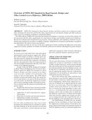
REFERENCES<br />
1. B Maidl, M Herrenknecht & L Anheuser, 1996.<br />
“Mechanised Shield Tunnelling” Ernst & Sohn<br />
2. W Burger, 2007. “Design Principles For So<strong>ft</strong><br />
Ground Cutterheads” Proc. RETC 2007, Toronto<br />
3. W Burger, 2006. “Hard Rock Cutterhead<br />
Design” Proc. NAT 2006, Chic<strong>ag</strong>o<br />
optimise muck flow.<br />
In many cases, the use of two-ring cutters<br />
in the inner face and centre area and singlering<br />
cutters for outer face and periphery area<br />
is a good compromise. Grain size limiters in<br />
the muck openings are installed to keep<br />
loose rock or large boulders at the tunnel<br />
face, so they can be broken down by the<br />
cutters. The design and layout of the size<br />
limiters has to be decided on the basis of<br />
anticipated ground conditions and installed<br />
crusher capacity. Special care also has to be<br />
given to the working levels of the different<br />
tool types on a mixed face cutterhead. Disk<br />
cutters should be positioned 30mm to<br />
50mm ahead of the so<strong>ft</strong> ground tools to<br />
ensure that hard rock or boulders are first<br />
attacked by the appropriate tool type.<br />
Positive results have been achieved on<br />
several mixed face slurry machines using<br />
specially designed Monoblock cutters, with<br />
a reduced risk of secondary wear to noncutting<br />
related elements of the cutters, such<br />
as split rings or hubs.<br />
The combination of mixed face cutterhead<br />
tool arrangements and jaw crusher-suction<br />
grill arrangements has proven effective when<br />
dealing with variable face conditions or<br />
cobbles and boulders. The need to manually<br />
intervene in order to remove or split boulders<br />
has been reduced dramatically and can be<br />
considered an exception these days.<br />
Clogging risks<br />
The problem of clogging can be addressed<br />
in several ways: choice of tools, quantity of<br />
fresh suspension supply, flushing and/or<br />
<strong>ag</strong>itation systems in the excavation<br />
chamber, flow in the chamber and the<br />
geometrical design and shape of cutterhead,<br />
excavation and pressure chamber.<br />
The preferred method in adhesive ground<br />
conditions is the use of wide cutting tools, in<br />
order to achieve bigger cuttings or clay<br />
chips. This also reduces the number of tools<br />
required to cover the full face. The use of<br />
fewer cutting tools increases the free areas<br />
between the individual tool sockets and<br />
therefore reduces the risk of “bridge<br />
building” and adhesion at the cutterhead.<br />
A high circulation or flushing quantity in<br />
the excavation chamber, in combination with<br />
a suitable cutterhead design, encour<strong>ag</strong>es<br />
free flow of excavated muck and reduces<br />
the time cuttings remain in the chamber to a<br />
minimum. Optimisation of the flow and a<br />
reduction in the time taken for muck to pass<br />
through the excavation chamber also have<br />
positive effects on wear reduction. This was<br />
demonstrated on the CTRL’s Thames Tunnel<br />
drives, in London, where two Mixshields<br />
were used to mine through chalk layers<br />
containing a large amount of abrasive flint.<br />
Flushing nozzles at the centre of the<br />
cutterhead supply fresh suspension close to<br />
the tunnel face where the soil excavation<br />
takes place. These feed lines in the rotating<br />
cutterhead are supplied via single or multiple<br />
channel rotary joints in the cutterhead<br />
centre. Feed line outlet arrangements in front<br />
of the submerged wall ensure a sufficient<br />
quantity of supply to the rear face of the<br />
cutterhead in the excavation chamber. For<br />
Mixshields operating in adhesive ground,<br />
there is a general tendency to feed fresh<br />
suspension in front of the submerged wall.<br />
Each individual supply line into the<br />
excavation chamber or the cutterhead can<br />
be controlled from the TBM’s cabin, with<br />
information about the flow and pressure of<br />
each individual line being fed back to the<br />
operator. Depending on the ground and the<br />
direction of cutterhead rotation, adaptation<br />
and optimisation of the feed-line flushing<br />
pattern is also possible. The installation of<br />
mixing arms behind the cutterhead is also a<br />
common solution to assist flushing.<br />
There are two ways to avoid adhesion or<br />
muck settlement in the pressure chamber<br />
area. Mechanical <strong>ag</strong>itator wheels in the invert<br />
area can assist muck flow. Alternatively,<br />
rotary sizers (see p39) can be used to cut<br />
clay chips to size, while not obscuring<br />
continuous conveying into the suction pipe.<br />
Additional flushing nozzles in the pressure<br />
chamber can also assist flow.<br />
T&T<br />
Part 2 of this article, due to be published<br />
next month, will focus on potential future<br />
developments of Mixshield technology.<br />
<strong>40</strong> Tunnels & Tunnelling International MAY 2008
REFERENCE PAPER:<br />
LIFTING THE LID ON MIXSHIELD PERFORMANCE.
MIXSHIELDS PART 2<br />
Li<strong>ft</strong>ing the lid on<br />
Mixshield performance<br />
Breakthrough of the 15.43m diameter<br />
Chongming Mixshield, in Shanghai, last month<br />
Aglance at the development of<br />
Mixshields over the past two<br />
decades (figure 8) shows an<br />
impressive increase in tunnel<br />
diameters. What’s more, from a TBM<br />
technology and manufacturing point of<br />
view, there is no obvious technical limit on<br />
further increases.<br />
Diameter increases are closely<br />
connected to the planned purpose of a<br />
tunnel. Two and three lane road tunnels<br />
have now been constructed with diameters<br />
of 11.2m (A86 Road Tunnel, Paris) and<br />
14.2m (Lefortovo Tunnel, Moscow), and a<br />
three-lane road tunnel is currently being<br />
built in China with a diameter of more than<br />
15m (Chongming, Shanghai).<br />
With these diameter increases, multipurpose<br />
or combined-use tunnels such as<br />
road/water stor<strong>ag</strong>e (SMART, Kuala<br />
Lumpur) or road/subway (Silberwald,<br />
Moscow) are also becoming more<br />
widespread. The ability to excavate very<br />
large diameters also creates additional<br />
potential for new us<strong>ag</strong>e concepts, like<br />
subway station platform tunnels.<br />
Twin-track rail tunnels with diameters of<br />
11.4m-12.6m already exist, and the<br />
increasing speed of trains and higher<br />
demands of operational safety<br />
(emergency rescue/escape concepts) will<br />
create further need for larger tunnel and<br />
machine diameters.<br />
Increasing performance demands,<br />
combined with experience from past<br />
projects, has also contributed to a continued<br />
increase in Mixshield operating pressures<br />
(see figure 9). Compared with EPB<br />
There remains much potential for the future development of Mixshields,<br />
particularly in terms of increased diameters and higher face support<br />
pressures. In part two of their article, Werner Burger and Gerhard<br />
Wehrmeyer, of Herrenknecht AG, look at two particularly influential<br />
projects and their impact on future Mixshield technology<br />
machines, the Mixshield’s use of a closed<br />
slurry circuit as the mucking system enables<br />
higher face pressures to be effectively dealt<br />
with. Controlling a large pressure drop in a<br />
continuous mucking system is also easier<br />
with a slurry circuit than with a screw<br />
conveyor, especially in heterogeneous or<br />
highly permeable ground conditions.<br />
A significant increase in face pressure<br />
affects all components of the shield that are<br />
exposed to the surrounding soil or<br />
groundwater. In particular, it affects:<br />
• Shield structure<br />
• Tail seal systems<br />
• Main bearing seal systems<br />
• Articulation seals<br />
• Shield thrust system<br />
• Slurry circuit<br />
• Equipment (and procedures) for face<br />
access<br />
Below: Fig 8 - Diameter development of Herrenknecht Mixshields<br />
Tunnel utilisation<br />
Road<br />
2 and 3 lane<br />
Railway<br />
double-track: 11,4-13m<br />
Metro<br />
double-track: 10m<br />
Railway<br />
single-track: 8-10m<br />
Metro<br />
single-track: 6-7m<br />
Utility tunnel<br />
segment aligning: 4,5m<br />
Sewer<br />
(pipe-jacking method):
MIXSHIELDS PART 2<br />
Operating pressure during advance [bar]<br />
15.0<br />
12.5<br />
10.0<br />
7.5<br />
5.0<br />
2.5<br />
2.5<br />
Mülheim<br />
ø 6.9m<br />
sandstone,<br />
mudstone<br />
Grauholz<br />
ø 11.6m<br />
sand, gravel<br />
molasse<br />
HERA<br />
ø 5.95m<br />
sand, gravel<br />
3.5 3.5<br />
Sydney<br />
ø 10.4m<br />
sandstone, clay<br />
0.0<br />
1985 1986 1987 1988 1989 1990 1991 1992 1993 1994 1995 1996 1997 1998 1999 2000 2001 2000 2003<br />
While it is possible to accomplish the<br />
required shield thrust by changing the<br />
number or diameter of the thrust cylinders,<br />
far more sophisticated technical solutions are<br />
required for seal systems. This is especially<br />
true of the main bearing seal system, which is<br />
one of the most sensitive design elements in<br />
high-pressure applications. For support<br />
pressures beyond 4 bar, pre-stressed<br />
cascade systems are used with the individual<br />
cascade chamber pressures automatically<br />
following the face pressure.<br />
Westerschelde<br />
ø 11.34m<br />
sand, clay<br />
Wesertunnel<br />
ø 11.67m<br />
gravel, clay, boulders<br />
4. Elbröhre<br />
ø 14.2m<br />
gravel, clay, boulders<br />
Above: Fig 9 - Operating pressure of Herrenknecht Mixshields<br />
Torque main drive [kNm]<br />
<strong>40</strong>,000<br />
35,000<br />
30,000<br />
25,000<br />
20,000<br />
15,000<br />
10,000<br />
5,000<br />
0<br />
Design Mixshield [kNm]<br />
Design EPB [kNm]<br />
4.0<br />
5.5<br />
7.5<br />
Hallandsas<br />
ø 10.53m<br />
design pressure<br />
13.0<br />
Diver assignment cutting tool change<br />
Hallandsas<br />
Grauholz<br />
SMART<br />
Chongming,<br />
Nanjing<br />
4. Elbröhre<br />
2 4 6 8 10 12 14 16<br />
Shield diameter [m]<br />
H8<br />
H3/4<br />
Zürich-Thalwil<br />
Above: Fig 10 - Torque comparison of cutterhead drives (Mixshield vs EPB-shield)<br />
Below: Fig 11 - Chongming alignment<br />
Tunnel<br />
9km<br />
Elevated highway<br />
6.5km<br />
A86<br />
Bridge<br />
10km<br />
Shanghai Changxing Chongming<br />
Island<br />
These systems can handle pressures far<br />
beyond 10 bar for an extended period of<br />
time in dynamic mode without the risk of<br />
overloading the individual lip seals. Longterm<br />
field experience with large diameter<br />
drive systems (bearing diameter range of<br />
6m) with face pressures of 7 bar to 10 bar<br />
already exist and full scale workshop and<br />
commissioning test programmes with<br />
pressures of 15 bar have been performed<br />
successfully. In emergencies or extended<br />
stopp<strong>ag</strong>es (long-term static mode),<br />
additional inflatable seals are included.<br />
While it is now possible to address highpressure<br />
operations by using appropriately<br />
designed equipment, the key questions<br />
relate more to the potential and the<br />
limitations for chamber access under<br />
hyperbaric conditions.<br />
Technical solutions to reduce the need<br />
for man access to the excavation chamber<br />
are available and currently include:<br />
• Accessible cutterheads for atmospheric<br />
cutter tool change (larger machines only)<br />
• Remotely activated standby cutter tools<br />
• Load detection and wear sensor systems<br />
However, these technical features will not<br />
totally eliminate the need for a “Plan B” for<br />
manual intervention to cover unforeseen<br />
conditions or worst-case scenarios.<br />
Based on the system of excavation and<br />
face support, a Mixshield requires lower<br />
cutterhead torque compared with an EPB<br />
shield (figure 10), as the cutterhead is only<br />
excavating the ground at the tunnel face<br />
into the suspension-filled excavation<br />
chamber. The excavated soil sinks towards<br />
the submerged wall opening in the invert<br />
due to gravity, assisted by the flow direction<br />
of the circulated slurry, and is carried to the<br />
suction pipe a<strong>ft</strong>er clearing the rock crusher<br />
and suction grille.<br />
An EPB shield requires a comparatively<br />
high torque at the cutterhead because, in<br />
addition to the soil excavation, the<br />
cutterhead itself acts as a mixing tool inside<br />
the excavation chamber, which is<br />
completely filled with muck.<br />
Therefore by adopting high torque EPB<br />
drive systems that have been developed for<br />
large diameter machines, such as that used<br />
on the M30 project, in Madrid (with<br />
125,000kNm), there is huge potential for the<br />
development of larger diameter Mixshield<br />
machines.<br />
Examples of projects<br />
The following presentation of the<br />
Chongming and A86 tunnel projects<br />
demonstrates the efficiency of current<br />
Mixshields and the value of development.<br />
Mixshield used as a shield with slurry<br />
supported face – Chongming, China: A<br />
twin tube road tunnel is currently being built<br />
beneath the Yangtze River in the city of<br />
Shanghai, comprising two 7160m-long bores<br />
with three lanes each. The tunnel, along with<br />
a new bridge, will link the islands of<br />
Changxing and Chongming to the freeway<br />
system and city. The geology of the tunnel is<br />
defined by its position in the river delta,<br />
consisting of so<strong>ft</strong> clay deposits and thin sand<br />
layers. The tunnel has an outside diameter of<br />
15m. The pre-cast concrete ring consists of<br />
9+1 segments with a length of 2m. The<br />
segments are 6<strong>40</strong>mm thick and weigh up to<br />
16.7 tons. The basic concept of the two<br />
Mixshield machines for the project is based<br />
on experiences from the Mixshield used at<br />
32 Tunnels & Tunnelling International JUNE 2008
MIXSHIELDS PART 2<br />
Above: Fig 12 - Accessible cutterhead: Design (le<strong>ft</strong>); front view (middle), view from inside (right)<br />
the fourth Elbe Tunnel and advancements in<br />
large diameter shield developments in high<br />
water pressure conditions. With a shield<br />
diameter of 15.43m, the two machines are<br />
currently the world’s largest diameter shields.<br />
The Mixshield machines have following<br />
technical features:<br />
• The shields are designed for an<br />
anticipated operational pressure of 6 bar<br />
at springline level. Due to the underwater<br />
application, and nearly straight alignment,<br />
(Rmin = 4.000m), a shield articulation joint<br />
was not included<br />
• The invert area of the Mixshield is<br />
equipped with two <strong>ag</strong>itator wheels<br />
(Ø1.900mm), which assist the material<br />
flow to the grille and a 500mm diameter<br />
suction pipe. Submerged wall gate,<br />
bentonite nozzles, cutting wheel and<br />
extensive excavation chamber flushing<br />
arrangements complete the Mixshield<br />
configuration to address the so<strong>ft</strong> soil<br />
conditions and potential clogging risks<br />
• The double shell tailskin with integrated<br />
grout lines has a three-row wire brush seal<br />
and an inflatable emergency seal system.<br />
Furthermore, freezing lines are integrated<br />
into the tail shield, which, in case of<br />
emergency, can be used for ground<br />
freezing around the machine to minimise<br />
the risk of water inrush during brush seal<br />
changes or repair works<br />
• The cutterhead is designed with six main<br />
spokes accessible under atmospheric<br />
pressure. To reduce the need for<br />
pressurised face access, one complete<br />
set of cutting tools (covering the entire<br />
face area) is exchangeable under<br />
atmospheric conditions from within the<br />
cutterhead spokes. To suit to the<br />
anticipated geology, the cutterhead was<br />
equipped with massive scrapers. Two<br />
hydraulically operated overcutters can<br />
create an overcut of <strong>40</strong>mm in radius. The<br />
cutterhead front and outer areas, as well<br />
as the rear, are designed to be durable<br />
and wear resistant to cope with the single<br />
drives of more than 7000m (see p31).<br />
As an additional safety feature, the<br />
Mixshields are equipped with all<br />
components – such as air locks and<br />
installations – necessary for pressurised face<br />
access including saturation diving activities.<br />
The installed cutterhead drive power is<br />
3750kW and the bearing diameter is 7.6m.<br />
The torque of the variable frequency<br />
electrical drive is 34800kNm, the shield<br />
thrust capacity is 203000kN and the TBM<br />
system is designed for a nominal mining<br />
speed of 45mm/min.<br />
The three-section backup system has an<br />
overall length of 118m and is divided into<br />
primary backup, bridge section and<br />
Below: Breakthrough of the Westerschelde machine, in The Netherlands<br />
JUNE 2008 Tunnels & Tunnelling International 33
MIXSHIELDS PART 2<br />
a) Operation mode slurry b) Operation mode EPB<br />
Above: Fig 13 - Machine concept of the<br />
A86 Mixshield, used in Paris, France<br />
secondary backup.<br />
The primary backup, or first three-deck<br />
trailer, contains all the hydraulic power<br />
packs and electrical systems for the supply<br />
and operation of the shield, along with<br />
slurry pumps and backfill grout system. For<br />
an even distribution of the wheel loads the<br />
trailer contains an integrated support<br />
system of auxiliary rail elements (steel invert<br />
slabs) and multi-wheel sets. The<br />
prefabricated 35 ton invert elements are<br />
installed in the area under the 67m bridge<br />
section. The supply crane system is<br />
installed inside the bridge cross-section to<br />
transfer segments, grout and other<br />
consumables to the TBM. All installations<br />
and workplaces for extension of services<br />
are located in the third section, along with<br />
ancillary equipment.<br />
The machine is supplied with segments<br />
and grout by rubber-tired transport<br />
vehicles, which travel in convoy and carry<br />
Below: The A86 machine breaks through<br />
either segments only or segments and<br />
grout tanks. The segment transfer on the<br />
backup is done by segment crane and a<br />
segment feeder. The grout is supplied in<br />
transfer tanks to the first backup.<br />
The shield structures and assemblies of<br />
the 132m-long and 2,300 ton TBMs were<br />
manufactured in Shanghai. Cutterheads<br />
and other main components such as drive<br />
assemblies and thrust cylinders were<br />
manufactured in Germany and shipped to<br />
China. A<strong>ft</strong>er shop acceptance, the TBM<br />
was disassembled and transported to the<br />
start sha<strong>ft</strong> about 6km from the workshop.<br />
Tunnelling started for the first tube in<br />
September 2006, and in January 2007 for<br />
the second. In March 2008, the first 7160m<br />
tunnel was about 90% complete and the<br />
second about 70%. Constant weekly<br />
performances of 90-120m are now being<br />
achieved by each TBM. Both drives are<br />
scheduled to finish in 2008 (the first TBM in<br />
May, and second in September), almost a<br />
year ahead of the project schedule.<br />
Mixshield used in differing operational<br />
modes – A86 tunnel: To close the gap in<br />
the A86 orbital motorway, a 10.1km-long,<br />
two-deck road tunnel for cars has been<br />
built to the West of Paris. A second tunnel<br />
for trucks is planned for construction at a<br />
later st<strong>ag</strong>e. Two levels, with three lanes<br />
each, require an outer diameter of 11.565m.<br />
The tunnel crosses the entire spectrum of<br />
geological formations under Paris: Marl,<br />
clay, limestone, chalk and sand as well as<br />
three different groundwater levels. For<br />
optimum adaptation to the geological<br />
conditions, the machine had to operate in<br />
different modes:<br />
• As slurry shield with slurry supported face<br />
(slurry operation - see figure 13a)<br />
• As earth pressure balance (EPB) shield<br />
with face support provided by<br />
conditioned muck (see figure 13b)<br />
• In Semi-EPB, or compressed air, mode<br />
• In open mode (muck discharge via screw<br />
conveyor, non pressurised excavation<br />
chamber)<br />
The change between different operational<br />
modes is carried out within the tunnel.<br />
Shield and backup are equipped with the<br />
full range of equipment for each mode. For<br />
slurry mode, this included a full slurry circuit<br />
with submerged wall/pressure wall<br />
installation and also a rock crusher. For<br />
EPB mode, components such as screw<br />
conveyor and TBM conveyor were installed.<br />
The cutterhead is designed for use in all<br />
modes of operation without the need for<br />
modification. The cutterhead concept is a<br />
closed wheel type with a full set of mixed<br />
tool equipment including 17” backloading<br />
disc cutters and ripper tools for two<br />
directions of rotation.<br />
In slurry mode, the excavation chamber<br />
and the lower part of the pressure chamber<br />
are filled with bentonite slurry; the upper<br />
part of the pressure chamber contains the<br />
air bubble, and the entire area is<br />
pressurised. In EPB mode only, the<br />
excavation chamber is pressurised so the<br />
submerged wall becomes a pressure<br />
bulkhead. The pressure chamber is then at<br />
atmospheric pressure and can be used as a<br />
working chamber, only pressurised during<br />
34 Tunnels & Tunnelling International JUNE 2008
MIXSHIELDS PART 2<br />
Rueil-<br />
Malmaison<br />
Sandy ground in<br />
fontainebleau<br />
Sandy ground in<br />
beauchamp<br />
Oystermarl<br />
Open<br />
mode<br />
EPB<br />
VL1 (2000-2002) VL2 (2005-2007)<br />
EPB<br />
(closed mode)<br />
(semi mode)<br />
Plastic clay<br />
False poller's clay<br />
Limestone and<br />
green clay<br />
Above: Fig 14 - A86 Tunnel alignment<br />
A13 portal<br />
sha<strong>ft</strong><br />
face access. To change from EPB to slurry<br />
mode, the entire screw casing is moved<br />
back, thus clearing the submerged wall<br />
opening in the invert and the suction grille<br />
below. A<strong>ft</strong>er this, a specially designed jaw<br />
crusher moves from parked position to<br />
operational mode.<br />
Some of the slurry mode installations,<br />
such as the air bubble pressure regulation<br />
system or the bentonite circulation<br />
systems, can also be used in EPB mode<br />
when required. Having the two systems<br />
permanently available provides potential<br />
synergy.<br />
Apart from the ability to change modes<br />
of operation, the TBM also has the<br />
following technical key features:<br />
• To cater for EPB mode, installed<br />
cutterhead power is <strong>40</strong>00kW and the<br />
available cutterhead torque is<br />
35000kN/m. Shield thrust is 150000kN,<br />
and the designed advance speed is<br />
80mm/min<br />
• The slurry circuit with 1900m³/h flow<br />
volume is designed for a mining speed of<br />
50mm/min in slurry mode. The tunnel is<br />
runs uphill and the largest difference in<br />
height between portal and TBM is 160m.<br />
This configuration needed to be<br />
Limestone in champigny<br />
Mass limestone<br />
Supra gypsum marl<br />
Ventilation<br />
sha<strong>ft</strong> RD10<br />
Marl and crushed stone<br />
Sandy ground in auteuil<br />
Chalk<br />
Marl in meudon<br />
Slurry Slurry EPB<br />
Slurry<br />
Pont<br />
Colbert<br />
addressed in the design of the slurry<br />
circuit as, under some conditions, the<br />
friction losses in the discharge line are<br />
less than the geometrical height between<br />
TBM and treatment plant<br />
• A specially designed camera system for<br />
the excavation chamber was installed for<br />
the first time and successfully tested in<br />
semi EPB/compressed air or open mode<br />
• Due to the steep tunnel gradient of 4.5%<br />
rubber tired vehicles were used for<br />
segment and grout transport. At the<br />
tunnel portal a semi-automatic loading<br />
station for the vehicles was installed<br />
loading one complete multi stack<br />
truckload at the same time, which<br />
together with a quick unloading system in<br />
the gantry reduced the turnaround cycles<br />
The pre-cast invert slab elements for the final<br />
lower road deck were installed 200m behind<br />
the trailing gear, concurrent to the advance<br />
of the TBM. In November 2000, the machine<br />
started excavating the VL1 tunnel (figure 14)<br />
in open mode EPB configuration. The first<br />
150m in an incomplete starting configuration<br />
through chalk containing a high amount of<br />
flint was excavated in two-shi<strong>ft</strong> operation,<br />
quickly reaching mining speeds of<br />
80mm/min. A<strong>ft</strong>er having installed the TBM<br />
and portal systems in their final<br />
configuration, the operation was changed to<br />
three shi<strong>ft</strong>s.<br />
Following a fire in the<br />
rear section of the tunnel<br />
in 2002, mining activities<br />
were halted for three<br />
months. By October 2002,<br />
the TBM was operated in<br />
open mode, closed mode<br />
EPB with face pressures of<br />
1-2 bar and semi EPB<br />
mode. The semi EPB<br />
mode proved to be the<br />
most appropriate method<br />
Le<strong>ft</strong>: The 14.2m diameter<br />
Lefortovo Mixshield,<br />
before it was shipped to<br />
Moscow, Russia<br />
for excavating the stable but water bearing<br />
material, using the compressed air to<br />
control the water and achieving dry<br />
excavated material.<br />
With the ground conditions changing into<br />
Fontainebleau sand, the machine was<br />
changed in-tunnel to slurry mode and<br />
operated in that mode for one year<br />
achieving mining speeds of 50mm/min. The<br />
breakthrough of the first tunnel was in<br />
October 2003. The TBM was<br />
disassembled, transported and<br />
reassembled at the Pont Colbert starting<br />
portal for the VL2 tunnel.<br />
For the VL2 tunnel the TBM began<br />
excavation in slurry mode. Immediately,<br />
around 10m a<strong>ft</strong>er the portal, a major sixlane<br />
motorway had to be passed beneath<br />
with shallow cover. Launch and passing<br />
under the freeway was completed a<strong>ft</strong>er just<br />
nine days with no problems. A<strong>ft</strong>er 1.2km in<br />
slurry mode, the TBM was changed back to<br />
EPB mode, and a<strong>ft</strong>er passing an escape<br />
and ventilation sha<strong>ft</strong> at the deepest point of<br />
the VL2 tunnel the TBM mode was<br />
changed back to slurry <strong>ag</strong>ain. The machine<br />
arrived at the portal in August 2007.<br />
Conclusion<br />
Initiated by the requirements of numerous<br />
large scale projects around the world, the<br />
development of Mixshield technology has<br />
taken major steps forward, as illustrated in<br />
this and the previous article (T&TI, May p35).<br />
Numerous additional features are also<br />
currently on the drawing board or being<br />
used for the first time. These include:<br />
• Advanced wear detection systems for<br />
cutting tools and structure<br />
• Positive ground support of the tunnel wall<br />
along the shield skin<br />
• Advanced ground improvement scenarios<br />
for closed mode from within the machine<br />
• Total integration of the whole pack<strong>ag</strong>e of<br />
above ground and underground<br />
measurement, process and alignment<br />
control data for a controlled boring<br />
process (CBP)<br />
• Approaching diameters of 18m to 20m<br />
• Fully variable, multi-mode concepts<br />
(EPB/HD slurry/LD slurry)<br />
The ability to handle high water pressures,<br />
the potential for crusher installation, low<br />
power requirements, high accuracy of face<br />
pressure and settlement control, and<br />
favourable face configurations, are just<br />
some of the current advant<strong>ag</strong>es of<br />
Mixshield technology. The combination of<br />
these advant<strong>ag</strong>es along with the ability to<br />
change modes of operation, brings the<br />
concept close to combining the best of<br />
both worlds. Nevertheless, there is also still<br />
huge potential for future development of<br />
the technology, that will see even greater<br />
tunnelling challenges conquered. T&T<br />
36 Tunnels & Tunnelling International JUNE 2008
REFERENCE PAPER:<br />
THE LATEST TECHNOLOGY IN MECHANIZED TUNNELING –<br />
THE DESIGN OF THE WORLD’S LARGEST EPB AND<br />
SLURRY SHIELD TBMS.
Underground Space – the 4 th Dimension of Metropolises – Barták, Hrdina, Romancov & Zlámal (eds)<br />
© 2007 Taylor & Francis Group, London, ISBN 978-0-415-<strong>40</strong>807-3<br />
The latest technology in mechanized tunnelling – the design of the<br />
world’s largest EPB and slurry shield TBMs<br />
Dr.-Ing. E.h.Martin Herrenknecht & Dr.-Ing. K.Bäppler<br />
Herrenknecht AG, Germany<br />
ABSTRACT: The general increase in growth is a result of a worldwide growing need for an efficient infrastructure<br />
in the areas of transport, supply and disposal services. Topographical conditions in large cities and<br />
towns encour<strong>ag</strong>e tunnelling solutions, particularly by mechanized methods. The mechanized tunnelling process<br />
has captured the attention of the public sector. As a safe, settlement controlled tunnelling process it offers<br />
a beneficial alternative to other tunnel excavation methods. Innovative solutions are increasingly required for<br />
tunnelling projects with a high level of difficulty in terms of construction, such as large diameter inner-city tunnels<br />
in heterogeneous grounds with high water pressures or the construction of long-distance tunnels integrating<br />
combined traffic systems in the tunnel cross section. Mechanized tunnel excavation moves into new dimensions<br />
especially regarding complexity of ground conditions, diameter, length and depth of underground constructions<br />
where the feasibility of other tunnelling methods is limited. This paper focuses on the design and technical<br />
challenges of the three largest so<strong>ft</strong> ground tunnel boring machines, two Slurry Shields (ø15.4 m) for the Shanghai<br />
River Crossing project and one Earth Pressure Balance Shield (ø15.2 m) used for a road tunnel project in Madrid<br />
in Spain.<br />
1 INTRODUCTION<br />
The tendency of the tunnel projects of today show<br />
the innovative move of using full-face TBMs with<br />
diameters larger than 14 metres.<br />
The resulting larger effective tunnel cross sections<br />
enable the possibilities of integrating more than 2 lanes<br />
of traffic or more than one traffic system in the tunnel<br />
or as shown with the example of the Storm Water Man<strong>ag</strong>ement<br />
and Road Tunnel project in Kuala Lumpur in<br />
Malaysia that the tunnel can take over more complex<br />
service functions.<br />
With the example of the two largest so<strong>ft</strong> ground<br />
tunnel projects in the world the latest technology in<br />
mechanised tunnelling will be described. The current<br />
largest Earth Pressure Balance Shield (Ø15.2 m) was<br />
in use for a road tunnel project in Madrid. The tunnel<br />
takes three lanes of traffic side by side on one level<br />
in the tunnel cross section. The two largest Mixshields<br />
(Ø15.4 m) designed for the Shanghai River Crossing<br />
Project in Asia are in use for the construction of a road<br />
tunnel carrying three lanes of traffic on one level and<br />
a safety pass<strong>ag</strong>e and a rescue lane in the bottom of the<br />
tunnel cross section.<br />
2 LARGEST EARTH PRESSURE BALANCE<br />
SHIELD (Ø15.2 M) USED FOR THE M30<br />
ROAD TUNNEL PROJECT IN<br />
MADRID<br />
Within the framework of the project Calle M30, the<br />
largest Earth Pressure Balance Shield (EPB) was in<br />
use for the construction of the north tunnel of the south<br />
bypass on Madrid’s highway M30.<br />
The tunnel route passes through a densely populated<br />
area and crosses beneath several structures such<br />
as three metro lines and railway tracks with minimal<br />
cover. The lowest distance from the tunnel crown to<br />
the structure is only 6.5 meters and this with an inside<br />
diameter of the tunnel of 13.37 m.<br />
The tunnel is constructed with reinforced concrete<br />
segments. One tunnel ring is composed of 9 + 1<br />
segments and has a length of 2.0 m.<br />
The EPB-Shield with a diameter of 15.2 m has been<br />
designed to suit the prevailing cohesive soil conditions,<br />
which have been predicted along the designed tunnel<br />
alignment. Clay and gypsum of stiff to hard consistency<br />
are characteristic of the geological conditions at<br />
tunnel level.<br />
1169
Large diameter EPB machines, and very large diameter<br />
EPB machines such as the one used on the<br />
south bypass tunnel for M30, require a very high cutting<br />
wheel torque compared for example to slurry<br />
TBMs.<br />
Machine technical and process technical factors<br />
such as drive unit and bearing unit, cutting wheel<br />
design and rotational speed have a relevant effect on<br />
the torque of the cutting wheel.The EPB-Shield for the<br />
Calle M30 project has a very high cutting wheel torque<br />
which amounts to 125,000 KNm.Therefore the cutting<br />
wheel is equipped with two concentrically arranged<br />
cutting wheels.<br />
The inner cutting wheel is installed in the free centre<br />
of the outer cutting wheel as a flat disc-type wheel. It<br />
is installed in the working surface of the outer cutting<br />
wheel and it is longitudinally displaceable relative to<br />
the outer cutting wheel.<br />
The rotational drives of both cutting wheels<br />
are completely independent with different rotational<br />
speeds in both directions of rotation.<br />
Part of the high torque is consumed in the mixing<br />
chamber, which is neutral with respect to the rolling<br />
of the machine. The torque is consumed between the<br />
cutting wheel and the tunnel face, it is the active part<br />
regarding the rolling of the TBM and can be resisted in<br />
loose soil by means of the skin friction or by transfer<br />
into the tunnel lining (reinforced concrete segments).<br />
If the torque rises beyond the value which can be<br />
resisted by the moment of friction of the shield shell,<br />
the machine will show a tendency to roll.<br />
With a diameter of 15.2 m and a torque of<br />
125,000 kNm the Herrenknecht EPB Shield beats all<br />
dimensions which have up to now been available on<br />
the mechanised shield tunnelling market.<br />
The drive unit of the inner cutting wheel comprises<br />
10 motors with a total power of 2,000 kW. To summon<br />
up the required power of 12,000 kW for the outer cutting<br />
wheel a new design was conceived. Altogether 50<br />
motors are necessary for the outer cutting wheel drive.<br />
They have been distributed around the main drive in<br />
two rows of 29 motors and 21 motors.<br />
The double cutting wheel design also improves<br />
the excavation process and the soil conditioning. The<br />
material excavation in the outer and inner area of the<br />
tunnel face can to a large extent be carried out at<br />
an optimised cutting tool speed. This is achieved by<br />
adjusting the differences in peripheral speeds, which<br />
can be applied to the cutter tools.<br />
The design of the outer cutting wheel area facilitates<br />
the arrangement of various cutter positions, which is<br />
normally not possible at all in the inner area as a<br />
favourable opening ratio must be maintained. A great<br />
difference in the cutter penetration depth between the<br />
outer and the inner area can be avoided by a higher<br />
rotational speed in the inner area, which has also the<br />
effect of reducing wear on the cutting tools.<br />
With regard to the soil conditioning with the double<br />
cutting wheel design and in particular with respect<br />
to the material removal and kneading or mixing<br />
effect, the mixing chamber can be divided into two<br />
zones. Both can be handled independently from each<br />
other.<br />
The areas of the inner and outer mixing chamber are<br />
in direct contact with each other so that an exchange<br />
of material between both zones is possible but not necessary.<br />
Because of the individual handling of the outer<br />
and inner mixing chamber, a homogenous consistency<br />
of the material in the chamber can be achieved.<br />
The cutting wheel is equipped with eight independent<br />
injection points at the front face of the centre<br />
cutting wheel and with 14 independent foam lances<br />
installed in the outer cutting wheel. Thus the injection<br />
of plasticizing <strong>ag</strong>ents such as foam is possible.Thereby<br />
36% of the total volume will be injected through the<br />
injection points, which are provided on the front face<br />
of the centre cutting wheel and the remaining 64% will<br />
be injected in the outer ring section.<br />
The start-up of the excavation process of the currently<br />
largest EPB-Shield begins when the inner cutting<br />
wheel starts rotating. The soil will be conditioned<br />
with foam through the rotary union, which is attached<br />
to the centre cutting wheel and above the stators. The<br />
stators are positioned in the centre area behind the cutting<br />
wheel in order to reduce the friction on the inside.<br />
To increase the mixing effect in the centre area, the<br />
displacement cylinders will be slowly extended.<br />
Figure 1. Injection of plasticizing <strong>ag</strong>ents through the two<br />
concentrically arranged cutting wheels of the EPB-Shield<br />
(Ø15.2 m) for M30.<br />
1170
It can be assumed that the soil will be wellconditioned<br />
up to a diameter of approximately 9 m and<br />
this will considerably reduce the starting torque of the<br />
outer cutting wheel.<br />
As soon as the centre area is conditioned, the outer<br />
cutting wheel starts turning and simultaneously adding<br />
foam. Thus, the complete excavation area will be<br />
homogeneously conditioned and the advance process<br />
can commence.<br />
The excavated material is transported out of the<br />
excavation chamber via three screw conveyors, which<br />
are integrated in the shield. They handle an excavated<br />
volume of 565 solid cubic meter per ring. There are<br />
two parallel screw conveyors (Ø1,250 mm), which are<br />
located in the lower part of the shield to remove the<br />
excavated material from the outer cutting wheel and<br />
to transport it back to the belt conveyor. The third and<br />
smallest screw conveyor (Ø600 mm) is arranged in the<br />
lower third of the central cutting wheel. It will remove<br />
the excavated material from this area and convey it<br />
back to the belt conveyor.<br />
The complete transport of the TBM from the manufacturing<br />
factory to the jobsite took two months. The<br />
main components of the Shield TBM were first transported<br />
with a river boat to the port of Rotterdam and<br />
then with two ships to Spain. For unloading the components<br />
a crawler crane with a capacity of 600 tons was<br />
necessary. The transport on the road lasted approximately<br />
nine days (50 km per night accompanied by<br />
the police).<br />
The excavation of the 3,525 m long north tunnel<br />
of the south bypass on Madrid’s highway M30 started<br />
on November 15, 2005 and could successfully be completed,<br />
on July 12, 2006, by the team of the contractors<br />
Acciona Infraestructuras S.A. and Ferrovial-Agroman<br />
S.A. in cooperation with Herrenknecht AG, a<strong>ft</strong>er only<br />
8 months of construction time.<br />
During advance the giant boring machine achieved<br />
convincing performances, which could be increased<br />
week by week and pushed to a best weekly performance<br />
of 94 rings or 188 m. The best daily performance<br />
amounted to 18 rings or 36 m and the strongest<br />
monthly performance could be reached in May 2006<br />
with considerable 758 m.<br />
A<strong>ft</strong>er the assembly and learning phase, weekly performances,<br />
which were clearly higher than 50 rings or<br />
100 m, could be achieved permanently. The tunnelling<br />
cycles were 30 minutes and the construction of a ring,<br />
consisting of 10 concrete segments, 13.9 tonnes each,<br />
could be carried out in approx. 50 minutes. During<br />
tunnelling a cycle time of less than 100 minutes could<br />
be achieved for the advance and the installation of a<br />
2,000 mm long ring.TheTBM supplier’s and construction<br />
firms’skilled personnel helped to reduce learning<br />
curve effects.<br />
A<strong>ft</strong>er approx. 1,000 m, 2,000 m and 3,000 m of<br />
tunnelling, a standstill of approx. 4 days was each<br />
scheduled in order to inspect the cutting tools, install<br />
tunnel belt boosters and carry out other maintenance<br />
operations that could not be done parallel to the<br />
advance. The target construction time of 12 months<br />
could clearly be underrun, and the 8-month tunnel construction<br />
time equals an excellent TBM performance<br />
of more than 450 m per month.<br />
3 LARGEST MIXSHIELD (Ø15.4 M)<br />
IN OPERATION IN SHANGHAI<br />
With the construction of the gigantic project “Shanghai<br />
Changxing Under River Tunnel” the region of the<br />
Yangtze delta near Shanghai will be further opened.<br />
The Yangtze is Chinas biggest river. Its yearly flow<br />
of 951.3 billion cubic metres of water amounts to<br />
approx. 52% of the total yearly quantity of all Chinese<br />
rivers.<br />
The greatest challenge of this project is the connection<br />
of the two river banks from the Pudong mainland<br />
with the island of Chongming. Two parallel motorway<br />
tunnels with a length of 8,950 m each will be<br />
built between the mainland Pudong and the island<br />
of Changxing. A bridge will connect the island of<br />
Changxing with the island of Chongming.<br />
Since the waterway between the mainland Pudong<br />
and the island Changxing is a very busy main shipping<br />
route, the tunnel solution was preferred instead of a<br />
bridge construction.<br />
With a length of 80 km and a width of 20 km,<br />
Chongming is the third biggest island of China. The<br />
island Changxing with a population of about 30,000 is<br />
characterised by the establishment of industries with<br />
three large shipping services.<br />
The two parallel tunnels will run beneath the largest<br />
river of China with the currently largest two tunnel<br />
boring machines. The Mixshields have a shield diameter<br />
of 15.43 m. Each of the tunnel tubes will integrate<br />
two levels, of which the upper level will contain three<br />
lanes for motor traffic and the lower level is planned<br />
to integrate a rescue lane in the centre and a safety<br />
pass<strong>ag</strong>e.<br />
The planned construction period of the Chongming<br />
Yangtze River CrossingTunnel near Shanghai amounts<br />
to four years.<br />
The challenges for the design of the two largest<br />
Mixshields for the river crossing were on the one hand<br />
the large shield diameter of 15.43 m and on the other<br />
hand the predicted geological and hydrological conditions.<br />
Each tunnel will have a total length of approx.<br />
7,170 m with a gradient of ±2.9%.<br />
The two Mixshields are adapted to the local geological<br />
and hydrological conditions featuring clayey<br />
formations and very high groundwater pressures. The<br />
entire tunnel will be built in very weak, clayey soils<br />
below the groundwater table. Characteristic of the<br />
1171
Figure 2.<br />
Figure 3.<br />
World’s largest Mixshield Ø15.4 m for Shanghai.<br />
Changjian under River Tunnels, Shanghai.<br />
expected geology are local intercalations of silty and<br />
sandy layers and shell residues.<br />
Due to a ground-water level of up to 47 m above<br />
the centre of the tunnel, the TBMs are designed for a<br />
maximum working pressure of 6.5 bar. At the deepest<br />
point the tunnel will run about 65 m below the<br />
surface.<br />
The tunnel lining consists of precast reinforced concrete<br />
segments with an inside diameter of 13.7 m. One<br />
tunnel ring consists of 9 + 1 segments and has a length<br />
of 2 m. For both tunnels altogether 7,500 segment rings<br />
are needed. They will be delivered with two special<br />
trucks from the segment fabrication yard, which is<br />
about 1.5 km away, to the jobsite.<br />
A feature of the cutting wheel design are six accessible<br />
main spokes, which are sealed <strong>ag</strong>ainst the water<br />
pressure.To avoid adhesion of sticky clay at the cutting<br />
wheel, the centre area is equipped with an own slurry<br />
circuit. Large openings in the cutting wheel optimise<br />
the flow of material and reduce the risk of block<strong>ag</strong>e of<br />
material in the centre.<br />
In order to get reliable information about the condition<br />
of the so<strong>ft</strong> ground tools and buckets, especially<br />
in the loaded outer area of the cutting wheel, ten cutting<br />
tools (2 buckets and eight so<strong>ft</strong> ground tools) are<br />
equipped with an electronic wear detection system.<br />
The system generates online data on the state of<br />
the selected cutting tools and gives early warning of<br />
possible wear to the TBM staff.<br />
With this electronic wear detection system maintenance<br />
works can be planned and the service life of<br />
the tools can be optimised, thereby minimising costly<br />
chamber accesses under compressed air.<br />
The heart of the system is a new tool support with<br />
integrated sender electronics.This is permanently connected<br />
to the so<strong>ft</strong> ground tool through induction loops<br />
and “detects” whether the wear limit is reached. For<br />
this purpose the sender is electrically connected with<br />
a power supply. If the probe is intact a certain current<br />
flows but if the probe is destroyed due to wear of the<br />
tool this is “sensed” by the sender through a significantly<br />
higher fault current. The sender is inductively<br />
connected with the receiver and the tool probe through<br />
a small gap. A LED informs the machine driver of the<br />
wear. With this automatic method of wear detection<br />
unnecessary maintenance could be avoided.<br />
The design of the cutting wheel was conceived in<br />
order to allow man access to its interior space under<br />
atmospheric air pressure, sealed from the ground water<br />
pressure outside.<br />
Tool change devices, which are integrated in the cutting<br />
wheel, allow the personnel to replace tools under<br />
atmospheric conditions from the interior of the cutting<br />
wheel.<br />
The tool change device has two functions:<br />
1 To serve as receptacle for the tools.<br />
2 To allow the outward and inward airlock transit of<br />
the tools.<br />
In order to flush the devices there are flushing<br />
connections installed on the rear case.<br />
This tool change device consists of the following<br />
main components:<br />
1 Front casing. This forms the connection to the steel<br />
structure of the cutterhead and is circumferentially<br />
welded to it.<br />
2 Rear casing. It is flange-mounted to the front casing<br />
and assumes in connection with the front casing the<br />
guidance of the slider and of the sliding pipe.<br />
3 Slider.<br />
4 Sliding pipe. The sliding pipe receives the cutting<br />
tool.<br />
The sliders are opened in the working position. In<br />
this position the cutting wheel is made water tight by<br />
the front seal. In case of dam<strong>ag</strong>e of this seal, the circumferential<br />
profile seal located around the slider and<br />
the rear seal would assure the leak tightness.<br />
A further feature, which has to be mentioned, is<br />
the installation of road elements by the back-up of the<br />
Mixshield. The back-up is composed of three trailers.<br />
The first one contains all necessary equipment and<br />
supply material for the functioning of the excavation<br />
1172
process. The second trailer is a bridge construction to<br />
allow free space of ±20 m for placing the road elements,<br />
which are precast concrete parts of 2 m length<br />
in dimension, 4.30 m in width and 4.56 m in height.<br />
Each element has a weight of approx. 35 tons.<br />
Supplies will be delivered to the TBM with trucks.<br />
They will drive along these rectangular road elements<br />
which are placed along the centre of the bottom of<br />
the tunnel. The trucks will be unloaded in the back-up<br />
trailer number 3.<br />
Back-up number 1 will run on invert slabs. These<br />
are placed on the already built segment ring and will<br />
be taken out and moved to the front as soon as the<br />
first back-up trailer passed this section. Back-up trailer<br />
number three runs on auxiliary rails.<br />
The tunnel excavation for the about 7,170 m per tunnel<br />
tube is expected to take about 34 months. The commissioning<br />
of the BOT-tunnels is planned for 2010.<br />
near Shanghai and the inner-city tunnelling for the<br />
M30 project in Madrid. Both projects illustrate the<br />
feasibility of large diameter tunnels and are pointing<br />
the way for future projects regarding the excavation of<br />
even larger tunnel cross sections, long-distance bored<br />
tunnels and even deeper excavations.<br />
In general, it is important to have a good understanding<br />
of all the conditions of a project already in<br />
the planning st<strong>ag</strong>e. The geological information is of<br />
particular interest because the machine design will be<br />
adapted to the predicted geological conditions. It is<br />
increasingly important to avoid possible risks when<br />
tunnelling in urban areas and also in the open country<br />
when underpassing existing structures or rivers and to<br />
further adapt the technology to make it even more safe<br />
and efficient.<br />
4 CONCLUSION<br />
The two cited Shield TBM projects are characteristic<br />
of demanding conditions like the under river crossing<br />
1173