Coco Nutz! Vol 3 Issue 2, May 2007.pdf - TRS-80 Color Computer ...
Coco Nutz! Vol 3 Issue 2, May 2007.pdf - TRS-80 Color Computer ...
Coco Nutz! Vol 3 Issue 2, May 2007.pdf - TRS-80 Color Computer ...

You also want an ePaper? Increase the reach of your titles
YUMPU automatically turns print PDFs into web optimized ePapers that Google loves.
CoCoNuts! <strong>May</strong> 2007 <strong>Vol</strong>ume 3 <strong>Issue</strong> 2<br />
T H E L I F E A N D T I M E S O F T H E C O L O R C O M P U T E R<br />
Hardware Hacking<br />
The only way to get around the hardware<br />
limitations of the <strong>Coco</strong> is to add<br />
new hardware. Tandy did this with the<br />
Speech/Sound and Orchestra-90<br />
cartridges. They take over the task of<br />
sound generation from the CPU and<br />
DAC. The Orc-90 pack contains the<br />
equivalent of two 8-bit DACs (actually<br />
just resistor arrays on chips) and<br />
produces both stereo and higher quality<br />
sound. The Orc-90 pack also provides<br />
a perfect platform for adding a new<br />
ADC to the <strong>Coco</strong> to simplify and<br />
increase the sampling rate for digitally<br />
recording programs.<br />
I chose the ADC0<strong>80</strong>2 which used to<br />
be sold by Tandy (276-1792). This<br />
chip (except for speed) was ideal as it<br />
could be directly connected to the<br />
6<strong>80</strong>9 data bus. Since I needed to both<br />
read and write to the chip, I had to add<br />
read addressing to the Orc-90. I chose<br />
to piggy back another 74LS138 on top<br />
IC3 of the Orc-90. A low profile IC<br />
socket was soldered to IC3 except for<br />
pins 5, 14, and 15 which had their legs<br />
bent up. Pin 5 was used as an "enable"<br />
line and grounded, pin 14 was<br />
left unconnected, and pin 15 was<br />
connected to pin 1 (CS) of the ADC.<br />
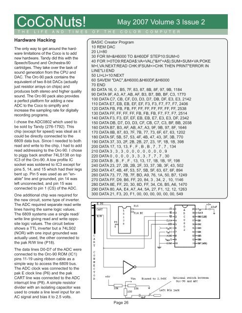
One additional chip was required for<br />
the new circuit, some type of inverter.<br />
The ADC required separate read write<br />
lines having the same logic values.<br />
The 6<strong>80</strong>9 systems use a single read/<br />
write line giving read and write opposite<br />
logic values. The circuit below<br />
shows a TTL inverter but a 74LS02<br />
(NOR) with one input grounded was<br />
actually used, the other connected to<br />
the pak R/W line (P18).<br />
The data lines D0-D7 of the ADC were<br />
connected to the Orc-90 ROM (IC1)<br />
pins 11-19 using ribbon cable as a<br />
simple way to access the 6<strong>80</strong>9 bus.<br />
The ADC clock was connected to the<br />
pak E clock line (P6) and the pak<br />
CART line was connected to the ADC<br />
interrupt line (P8). A simple resistor<br />
divider with an isolating capacitor was<br />
used to create a line level input for an<br />
AC signal and bias it to 2.5 volts.<br />
BASIC Creator Program<br />
10 REM DAC<br />
20 LI=<strong>80</strong><br />
30 FOR M=&H6000 TO &H60DF STEP10:SUM=0<br />
40 FOR I=0TO9:READA$:VA=VAL("&H"+A$):SUM=SUM+VA:POKE<br />
M+I,VA:NEXT:READ CHK:IFSUMCHK THEN PRINT"ERROR IN<br />
LINE"LI:END<br />
50 LI=LI+10:NEXT<br />
60 SAVEM "DAC",&H6000,&H60DF,&H6000<br />
70 END<br />
<strong>80</strong> DATA 16, 0 , B5, 7F, 83, 87, 8B, 8F, 97, 9B, 1184<br />
90 DATA 9F, A3, A7, AB, AF, B3, B7, BB, BF, C3, 1770<br />
100 DATA C7, CB, CF, D3, D3, D7, DB, DF, E3, E3, 2142<br />
110 DATA E7, EB, EB, EF, EF, F3, F3, F7, F7, F7, 2406<br />
120 DATA FB, FB, FB, FF, FF, FF, FF, FF, FF, FF, 2538<br />
130 DATA FF, FF, FF, FF, FB, FB, FB, F7, F7, F7, 2514<br />
140 DATA F3, F3, EF, EF, EB, EB, E7, E3, E3, DF, 2342<br />
150 DATA DB, D7, D3, D3, CF, CB, C7, C3, BF, BB, 2038<br />
160 DATA B7, B3, AF, AB, A7, A3, 9F, 9B, 97, 8F, 1646<br />
170 DATA 8B, 87, 83, 7F, 7B, 77, 73, 6F, 67, 63, 1202<br />
1<strong>80</strong> DATA 5F, 5B, 57, 53, 4F, 4B, 47, 43, 3F, 3B, 770<br />
190 DATA 37, 33, 2F, 2B, 2B, 27, 23, 1F, 1B, 1B, 398<br />
200 DATA 17, 13, 13, F , F , B , B , 7 , 7 , 7 , 134<br />
210 DATA 3 , 3 , 3 , 0 , 0 , 0 , 0 , 0 , 0 , 0 , 9<br />
220 DATA 0 , 0 , 0 , 0 , 3 , 3 , 3 , 7 , 7 , 7 , 30<br />
230 DATA B , B , F , F , 13, 13, 17, 1B, 1B, 1F, 198<br />
240 DATA 23, 27, 2B, 2B, 2F, 33, 37, 3B, 3F, 43, 502<br />
250 DATA 47, 4B, 4F, 53, 57, 5B, 5F, 63, 67, 6F, 894<br />
260 DATA 73, 77, 7B, 7F, BD, A9, 76, 1A, 50, B7, 1249<br />
270 DATA FF, D9, B6, FF, 20, 84, 3 , 34, 2 , 10, 1146<br />
2<strong>80</strong> DATA 8E, FF, 20, 30, 8D, FF, 34, C6, B5, A6, 1470<br />
290 DATA <strong>80</strong>, AA, E4, A7, A4, 5A, 27, F1, 12, 12, 1263<br />
300 DATA 21, F3, 20, F1, 00, 00, 00, 00, 00, 00, 549<br />
Page 26