Quanser Analog Output Connections
Quanser Analog Output Connections
Quanser Analog Output Connections

Create successful ePaper yourself
Turn your PDF publications into a flip-book with our unique Google optimized e-Paper software.
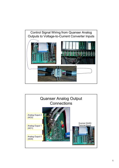
Control Signal Wiring from <strong>Quanser</strong> <strong>Analog</strong><br />
<strong>Output</strong>s to Voltage-to-Current Converter Inputs<br />
<strong>Quanser</strong> <strong>Analog</strong> <strong>Output</strong><br />
<strong>Connections</strong><br />
<strong>Analog</strong> Ouput 2<br />
(AO2)<br />
<strong>Analog</strong> Ouput 1<br />
(AO1)<br />
<strong>Quanser</strong> MultiQ<br />
Terminal Board<br />
<strong>Analog</strong> Ouput 0<br />
(AO0)<br />
1
Voltage-to-Current Converters<br />
J2<br />
J3<br />
J1<br />
Note: these<br />
modules are<br />
numbered<br />
according to the<br />
joint that they<br />
control (i.e. J1<br />
controls joint 1).<br />
<strong>Quanser</strong> <strong>Analog</strong> <strong>Output</strong> Wiring<br />
Pin out of the 9 pin connection between the analog output<br />
connections of the <strong>Quanser</strong> MultiQ board and SAMII’s<br />
existing voltage-to-current converters:<br />
<strong>Analog</strong><br />
<strong>Output</strong><br />
Connection<br />
Voltage to<br />
current<br />
module<br />
Pin<br />
# Function Wire color<br />
1 Joint 1 + Green AO 0 + J1 +<br />
6 Joint 1 - Black/Green AO 0 - J1 -<br />
2 Joint 2 + White AO 1 + J2 +<br />
7 Joint 2 - Black/White AO 1 - J2 -<br />
3 Joint 3 + Red AO 2 + J3 +<br />
8 Joint 3 - Black/Red AO 2 - J3 -<br />
Note: black/green denotes a solid black wire that is paired with the green<br />
wire in a foil wrapper i.e. the black wire associated with the green wire, not<br />
a black wire with a green stripe (the same is true for black/red and<br />
black/white).<br />
2
Male 9-Pin Pin Out<br />
Pin 1: AO0/J1 +<br />
(green)<br />
Pin 2: AO1/J2 +<br />
(white)<br />
Pin 3: AO2/J3 +<br />
(red)<br />
Pin 6: AO0/J1 -<br />
(black/green)<br />
Pin 7: AO1/J2 -<br />
(black/white)<br />
Pin 8: AO2/J3 -<br />
(black/red)<br />
Female 9 Pin Pin Out<br />
Pin 3: AO2/J3 +<br />
Pin 1: AO0/J1 +<br />
Pin 2: AO1/J2 +<br />
Pin 8: AO2/J3 -<br />
Pin 6: AO0/J1 -<br />
Pin 7: AO1/J2 -<br />
3
Male/Female Mirror Image Pin Out<br />
Pin 1 Pin 5<br />
Pin 1<br />
Pin 6<br />
Pin 9<br />
Pin 6<br />
Sorry if this is completely obvious and unnecessary, but I<br />
want to be totally explicit in my documentation.<br />
Voltage-to-Current Module<br />
<strong>Connections</strong> for Joint 1<br />
J1 +<br />
Green<br />
J1 -<br />
Black<br />
4
Voltage-to-Current Module<br />
<strong>Connections</strong> for Joints 2 & 3<br />
J2 +<br />
White<br />
J2 -<br />
Black<br />
J3 +<br />
Red<br />
J3 -<br />
Black<br />
5