

S1-AM009-L - DDKS Industries, hydraulic components distributor
S1-AM009-L - DDKS Industries, hydraulic components distributor
S1-AM009-L - DDKS Industries, hydraulic components distributor

You also want an ePaper? Increase the reach of your titles
YUMPU automatically turns print PDFs into web optimized ePapers that Google loves.
UNIT DISASSEMBLY<br />
DISASSEMBLY PROCEDURE<br />
continued<br />
bearing 36. Guide sleeve must be placed upward. Cover the block with a dust-proof plastic<br />
film.<br />
c) Place PC valve 28 with the machined face that attaches to port block 2 upward. Cover<br />
the PC valve with dust-proof plastic film. If unit contains a torque limiter, place torque limiter in<br />
a plastic bag.<br />
proceed to INSPECTION<br />
Note: Further disassembly may be required if any of the following is observed:<br />
a) When cylinder barrel 3 is placed flat, the dowels 56 must protrude slightly. If otherwise<br />
or if the dowel is easily pushed in, perform the following steps (12) through (14).<br />
b) If the hanger 9 has little or no inclination against the shaft 8 or if it can easily be moved<br />
by hand, perform the following steps (15) through (17).<br />
c) If oil seal leakage or excessive ball bearing play is apparent, perform steps (18)<br />
through (22).<br />
d) If PC valve functions irregularly, perform the following steps (23) through (28).<br />
e) If “J” or “K” torque limiter valve functions irregularly, perform the following steps (29)<br />
through (33).<br />
f) If “T” torque limiter valve functions irregularly, perform the following steps (34) through<br />
(36).<br />
g) If guide sleeve is worn excessively, perform the following steps (37) and (38).<br />
12. Place cylinder barrel 3 on the fixture with the face upward. Compress spring 18 with a<br />
simple hand press and remove retaining ring 40 with pliers.<br />
13. Remove washer 27 and spring 18<br />
14. Remove cylinder barrel from fixture.<br />
Proceed to INSPECTION.<br />
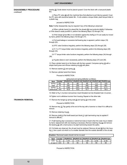
spring load and spring deflection as follows:<br />
item model PV/PVT-6 PV/PVT-10 PV/PVT-15 PV/PVT-20 PV/PVT-29<br />
spring lbs. 55 68 99 111 133<br />
load N 244 304 440 495 591<br />
spring in. 0.66 0.61 0.62 0.67 0.71<br />
deflection mm 16.8 15.6 15.7 16.9 18.0<br />
15. Refer to Fig. 5, trunnion removal tool. Insert threaded rod into threaded hole in trunnion.<br />
16 Tighten nut to withdraw trunnion from housing. Repeat on the other side.<br />
TRUNNION REMOVAL<br />
17. Remove the hanger 9, spring seat 20 and spring 19 in this order.<br />
Proceed to INSPECTION.<br />
18. Remove key 12. Tap gently at the end of the key with a hammer or chisel if it is difficult to<br />
remove.<br />
19. Remove retaining ring 41.<br />
20. Remove shaft 8. (Pull shaft toward port block 2. Light hammering may be applied if<br />
removal is difficult.)<br />
21. If ball bearing play is excessive or abnormal noise is heard when the outer ring is rotated<br />
by hand, replacement with new bearing is necessary. Remove retaining ring 42 and remove<br />
the bearing 35 with a hand press or by light hammering toward the spline.<br />
22. If oil leaks are observed, the oil seal must be replaced. Remove oil seal 38 from the housing<br />
1. Use a push rod which is of a smaller diameter than the outside diameter of the oil seal.<br />
Caution: Removed seals should not be re-used.<br />
item model PV/PVT-6 PV/PVT-10 PV/PVT-15 PV/PVT-20 PV/PVT-29<br />
O.D. in. 1.77 1.77 1.97 2.16 2.16<br />
of seal mm 45 45 50 55 55<br />
Proceed to INSPECTION.<br />
12


