

S1-AM009-L - DDKS Industries, hydraulic components distributor
S1-AM009-L - DDKS Industries, hydraulic components distributor
S1-AM009-L - DDKS Industries, hydraulic components distributor

Create successful ePaper yourself
Turn your PDF publications into a flip-book with our unique Google optimized e-Paper software.
ASSEMBLY PROCEDURE<br />
Carefully clean the valve body 28-1 and spool 28-2 and soak in clean <strong>hydraulic</strong> fluid.<br />
Check O-Rings 28-8 and 28-9 for deformation and wear (as given in no. 28 of<br />
"INSPECTION") and when determined to be in good condition, assemble 28-8 to cap,<br />
28-3, and 28-9 to spring seat 28-4.<br />
For the ‘L’ compensator only, install pin 28-4 into spool 28-2.<br />
Carefully insert spool 28-2 into the bore in the valve body 28-1. (Spool and body are<br />
matched set.) Install plug 28-14 in body.<br />
Assemble spring seats 28-4 and spring seat 28-5 on both ends of the spring 28-6 and<br />
assemble into the valve body.<br />
With adjusting screw 28-11 and nut 28-22 set on the cap, place the cap on the spring<br />
seat 28-4 and screw into the threaded hole on the valve body. Tighten until the edge<br />
surface is flush.<br />
To install seat 28-15, insert open end into bore and press in place. Install plug<br />
28-20 and tighten.<br />
Assemble washer 28-19 and spring 28-7 on adjusting screw 28-18, assemble cone 28-<br />
16 in spring and assemble into the valve body.<br />
Set adjusting screw to measurement taken at disassembly and lock in place with nut<br />
28-12 Cover with acorn nut 28-22.<br />
After checking the O-ring 28-10 for deformation and wear, coat the mounting surface<br />
facing the valve body with lithium grease and install the O-ring.<br />
‘J’ AND ‘K’TORQUE LIMITER<br />
The torque limiter functions in conjunction with the ‘F’ or ‘L’ compensator described previously.<br />
B<br />
A<br />
‘J’ AND ‘K’TORQUE<br />
LIMITER CIRCUIT<br />
D<br />
V<br />
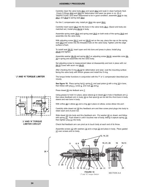
See figure 10. Place spring hat 9, spring 5, and seal piston 4 with o-ring 19 in bore,<br />
then follow with plug 1, screw 2, and nuts 20 and 3.<br />
Press dowel 25 into fedback arm 7.<br />
Using grease to hold it in place, place sleeve 6 on dowel 25 in hole in feedback arm 7,<br />
then place feedback arm in body 16 so that spool 8 can be slid thru front bore in body,<br />
sleeve and rear bore in body.<br />
With orifice 26 in elbow 21 and o-ring 19 in place on elbow, screw elbow into port.<br />
Carefully slide dowel rod 18 thru feedback arm and then screw pivot plugs into body to<br />
retain each end of pivot rod.<br />
Slide dowel 10 into body and thru feedback arm. Put washer 22 on dowel, and follow<br />
with spring 15. Push dowel in until it touches rear of body, letting it capture spring 15,<br />
then tighten plug 11 into body.<br />
Check that feedback arm can pivot as to touch body at each end of its throw.<br />
Assemble screws 12 with washers 14 and o-rings 23 and place in body. Place gasket<br />
17 over screws and on body.<br />
12, 14, 23<br />
5 8 8, 9 9<br />
A<br />
19, 21, 26 16 16 18,13<br />
13<br />
28<br />
3 3 20 20 11<br />
22 19 19 44 15 15 10 10 22 22<br />
A 77 6 24 11 17<br />
25 25<br />
FIGURE 10<br />
‘J’ and ‘K’ torque limiter<br />
FIGURE 10<br />
'J' and 'K' torque limiter<br />
SECTION A-A A-A<br />
24


