

S1-AM009-L - DDKS Industries, hydraulic components distributor
S1-AM009-L - DDKS Industries, hydraulic components distributor
S1-AM009-L - DDKS Industries, hydraulic components distributor

You also want an ePaper? Increase the reach of your titles
YUMPU automatically turns print PDFs into web optimized ePapers that Google loves.
ASSEMBLY PROCEDURE<br />
Place cylinder barrel 3 on a clean sheet of paper or cloth and insert the three dowels<br />
56 into the holes located outside of the spline hole. Place the holddown ball 14 on top.<br />
Compress manually and ascertain spring 18 force.<br />
BARREL,<br />
PISTON/SHOE/RETAINER<br />
Hold the shoe retainer 15 horizontally with one hand, insert the 9 piston assemblies 5<br />
into the bores of the shoe retainer, in order of disassembly. The shoes should freely<br />
move on the piston.<br />
Support the shoe retainer horizontally and insert the piston assemblies 5 carefully into<br />
the cylinder barrel bores 3.<br />
HOUSING AND ROTATING<br />
GROUP<br />
Place the housing 1 so that the drive shaft 8 is horizontal. Assemble the cylinder barrel<br />
3, piston assembly 5, holddown ball 14 and shoe retainer 15 together onto the drive<br />
shaft.<br />
Do not force the drive shaft spline into the cylinder barrel groove but carefully rotate to<br />
engage, while applying slight thrust. The assembly is correct when the edge of the<br />
cylinder barrel is inserted approximately 1/3 inches below the edge of the housing.<br />
Place the housing with the shaft end pointing downwards on a fixture and coat the face<br />
of the cylinder barrel with clean <strong>hydraulic</strong> fluid. Place gasket 24 on the housing.<br />
PORT BLOCK ASSEMBLY<br />
Press needle bearing 36 into port block,till bearing bottoms in the bore. Press on the<br />
stamped side of the needle bearing.<br />
Place port block on press with support under adjusting screw pad. Press guide sleeve<br />
23 into port block.<br />
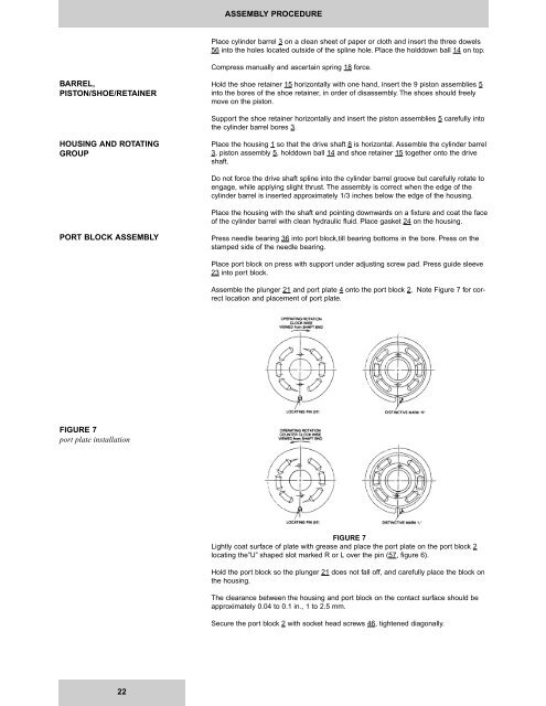
Assemble the plunger 21 and port plate 4 onto the port block 2. Note Figure 7 for correct<br />
location and placement of port plate.<br />
FIGURE 7<br />
port plate installation<br />
FIGURE 7<br />
Lightly coat surface of plate with grease and place the port plate on the port block 2<br />
locating the”U” shaped slot marked R or L over the pin (57, figure 6).<br />
Hold the port block so the plunger 21 does not fall off, and carefully place the block on<br />
the housing.<br />
The clearance between the housing and port block on the contact surface should be<br />
approximately 0.04 to 0.1 in., 1 to 2.5 mm.<br />
Secure the port block 2 with socket head screws 46, tightened diagonally.<br />
22


