

S1-AM009-L - DDKS Industries, hydraulic components distributor
S1-AM009-L - DDKS Industries, hydraulic components distributor
S1-AM009-L - DDKS Industries, hydraulic components distributor

Create successful ePaper yourself
Turn your PDF publications into a flip-book with our unique Google optimized e-Paper software.
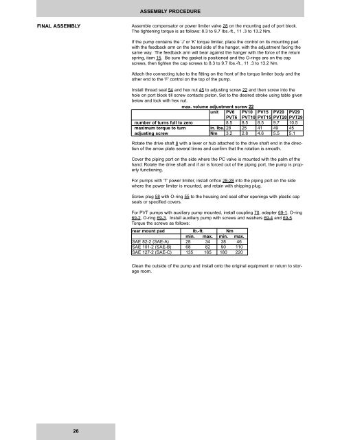
ASSEMBLY PROCEDURE<br />
FINAL ASSEMBLY<br />
Assemble compensator or power limiter valve 28 on the mounting pad of port block.<br />
The tightening torque is as follows: 8.3 to 9.7 Ibs.-ft., 11 .3 to 13.2 Nm.<br />
If the pump contains the ‘J’ or ‘K’ torque limiter, place the control on its mounting pad<br />
with the feedback arm on the barrel side of the hanger, with the adjustment facing the<br />
same way. The feedback arm will bear against the hanger with the force of the return<br />
spring, item 15. Be sure the gasket is positioned and the O-rings are on the cap<br />
screws, then tighten the cap screws to 8.3 to 9.7 Ibs.-ft., 11 .3 to 13.2 Nm.<br />
Attach the connecting tube to the fitting on the front of the torque limiter body and the<br />
other end to the ‘F’ control on the top of the pump.<br />
Install thread seal 54 and hex nut 45 to adjusting screw 22 and then screw into the<br />
hole on port block till screw contacts piston. Set to the desired stroke using table given<br />
below and lock with hex nut.<br />
max. volume adjustment screw 22<br />
unit PV6 PV10 PV15 PV20 PV29<br />
PVT6 PVT10 PVT15 PVT20 PVT29<br />
number of turns full to zero 8.5 8.5 8.5 9.7 10.5<br />
maximum torque to turn in. lbs. 28 25 41 49 45<br />
adjusting screw Nm 3.2 2.8 4.6 5.5 5.1<br />
Rotate the drive shaft 8 with a lever or hub attached to the drive shaft end in the direction<br />
of the arrow plate several times and confirm that the rotation is smooth.<br />
Cover the piping port on the side where the PC valve is mounted with the palm of the<br />
hand. Rotate the drive shaft and if air is forced out of the piping port, the pump is properly<br />
functioning.<br />
For pumps with ‘T’ power limiter, install orifice 28-28 into the piping port on the side<br />
where the power limiter is mounted, and retain with shipping plug.<br />
Screw plug 58 with O-ring 55 to the housing and seal other openings with plastic cap<br />
seals or specified covers.<br />
For PVT pumps with auxiliary pump mounted, install coupling 70, adapter 69-1, O-ring<br />
69-2, O-ring 69-3, Install auxiliary pump with screws and washers 69-4 and 69-5.<br />
Torque the screws as follows:<br />
rear mount pad lb.-ft. Nm<br />
min. max. min. max.<br />
SAE 82-2 (SAE-A) 28 34 38 46<br />
SAE 101-2 (SAE-B) 68 82 90 110<br />
SAE 127-2 (SAE-C) 135 165 180 220<br />
Clean the outside of the pump and install onto the original equipment or return to storage<br />
room.<br />
26


