Atomic Weapons Research Establishment. Orford ... - English Heritage
Atomic Weapons Research Establishment. Orford ... - English Heritage
Atomic Weapons Research Establishment. Orford ... - English Heritage

Create successful ePaper yourself
Turn your PDF publications into a flip-book with our unique Google optimized e-Paper software.
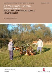
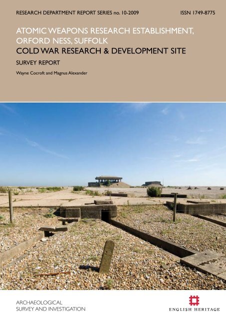
RESEARCH DEPARTMENT REPORT SERIES no. 10-2009 ISSN 1749-8775<br />
ATOMIC WEAPONS RESEARCH ESTABLISHMENT,<br />
ORFORD NESS, SUFFOLK<br />
COLD WAR RESEARCH & DEVELOPMENT SITE<br />
SURVEY report<br />
Wayne Cocroft and Magnus Alexander
‘This report has been prepared for use on the internet and the images within it have been<br />
down-sampled to optimise downloading and printing speeds. Please note that as a result<br />
of this down-sampling the images are not of the highest quality and some of the fine detail<br />
may be lost. Any person wishing to obtain a high resolution copy of this report should refer<br />
to the ordering information on the following page.’
<strong>Research</strong> Department Report Series 10-2009<br />
ATOMIC WEAPONS RESEARCH ESTABLISHMENT<br />
ORFORD NESS, SUFFOLK<br />
COLD WAR RESEARCH & DEVELOPMENT SITE<br />
Wayne D Cocroft and Magnus Alexander<br />
NGR: TM 4408 4856<br />
© <strong>English</strong> <strong>Heritage</strong><br />
ISSN 1749-8775<br />
The <strong>Research</strong> Department Report Series incorporates reports from all the specialist teams within the <strong>English</strong><br />
<strong>Heritage</strong> <strong>Research</strong> Department: Archaeological Science; Archaeological Archives; Historic Interiors <strong>Research</strong> and<br />
Conservation; Archaeological Projects; Aerial Survey and Investigation; Archaeological Survey and Investigation;<br />
Architectural Investigation; Imaging, Graphics and Survey, and the Survey of London. It replaces the former Centre<br />
for Archaeology Reports Series, the Archaeological Investigation Report Series and the Architectural Investigation<br />
Report Series.<br />
Many of these are interim reports which make available the results of specialist investigations in advance of full<br />
publication. They are not usually subject to external refereeing, and their conclusions may sometimes have to be<br />
modified in the light of information not available at the time of the investigation. Where no final project report<br />
is available, readers are advised to consult the author before citing these reports in any publication. Opinions<br />
expressed in <strong>Research</strong> Department reports are those of the author(s) and are not necessarily those of <strong>English</strong><br />
<strong>Heritage</strong>.<br />
Requests for hard copies can be made by emailing:<br />
Res.reports@english-heritage.org.uk<br />
or by writing to:<br />
<strong>English</strong> <strong>Heritage</strong>, Fort Cumberland, Fort Cumberland Road, Eastney, Portsmouth PO4 9LD<br />
Please note that a charge will be made to cover printing and postage.<br />
© ENGLISH HERITAGE 10 - 2009
SUMMARY<br />
The <strong>Atomic</strong> <strong>Weapons</strong> <strong>Research</strong> <strong>Establishment</strong>, <strong>Orford</strong> Ness, Suffolk, was operational<br />
between 1956 and 1972. Its primary task was environmental testing to simulate the<br />
conditions that nuclear weapons and their components might experience during trials and<br />
in service use. Here science and high politics merged, with investigations that were crucial<br />
to the credibility of the United Kingdom’s nuclear deterrent forces, the cornerstone of<br />
Cold War defence policy. Prior to the 20 th century <strong>Orford</strong> Ness was a rarely visited<br />
place; the main economic activity was animal grazing on reclaimed marsh land. During<br />
the First World War the Royal Flying Corps established a flying field on the marshes<br />
and associated buildings along ‘The Street’. It was principally used for experimental work<br />
into aerial machine guns, bombs, navigation, and photography, a role that continued into<br />
the inter-war period. In 1935, a small experimental radar team arrived and conducted<br />
experiments that were critical in proving the value of this technology. This report is<br />
primarily concerned with the development of the post-war <strong>Atomic</strong> <strong>Weapons</strong> <strong>Research</strong><br />
<strong>Establishment</strong>. To understand these developments a brief summary of the earlier military<br />
activity is also provided. <strong>Orford</strong> Ness is owned by the National Trust.<br />
CONTRIBUTORS<br />
The survey was carried out by Magnus Alexander, Wayne Cocroft, Elaine Jamieson, Sarah<br />
Newsome and Jonathan Millward. Professional ground photography was taken by Steve<br />
Cole and Roger J C Thomas.<br />
ACKNOWLEDGEMENTS<br />
<strong>English</strong> <strong>Heritage</strong> is especially grateful to Grant Lohoar and his team for ferrying the survey<br />
team to and from <strong>Orford</strong> Ness, and for providing other logistical support. We are also<br />
grateful to the National Trust’s regional archaeologist, Angus Wainwright, for his support<br />
and continued interest in this project.<br />
ARCHIVE LOCATION<br />
The National Monuments Record Centre,<br />
Kemble Drive,<br />
Swindon<br />
SN2 2G<br />
DATE OF RESEARCH<br />
The field survey was undertaken during June 2007.<br />
CONTACT DETAILS<br />
Wayne Cocroft, <strong>English</strong> <strong>Heritage</strong>, Brooklands Avenue, Cambridge, CB2 8BU<br />
wayne.cocroft@english-heritage.org.uk<br />
© ENGLISH HERITAGE<br />
<br />
10 - 2009
© ENGLISH HERITAGE 2009 10 -
CONTENTS<br />
Introduction 6<br />
Topography and land use 8<br />
Previous archaeological and historical research 10<br />
History 11<br />
The First World War 12<br />
Early radar research 13<br />
The Second World War 14<br />
Post-war bomb ballistics 15<br />
<strong>Atomic</strong> <strong>Weapons</strong> <strong>Research</strong> <strong>Establishment</strong> 1956-1972 20<br />
The 1958 Mutual Defence Agreement and its consequences 22<br />
The 1960s 23<br />
Project 441- L Cobra Mist 25<br />
Closure of AWRE <strong>Orford</strong> Ness 25<br />
Description 27<br />
The Royal Flying Corps flying field and buildings 27<br />
<strong>Orford</strong> Beach 32<br />
The magazine area 32<br />
Pre-war range buildings 35<br />
First phase AWRE buildings 36<br />
Laboratories 1, 2 and 3 39<br />
Second Phase AWRE Buildings 46<br />
Vibration test buildings – The Pagodas 48<br />
Magazine 52<br />
Final AWRE phases 53<br />
Site infrastructure 56<br />
Conclusions 57<br />
Aviation heritage 58<br />
Nuclear weapons research 58<br />
International connections 62<br />
© ENGLISH HERITAGE<br />
<br />
10 - 2009
Sources 64<br />
Primary sources 64<br />
Secondary sources 66<br />
Building list 68<br />
© ENGLISH HERITAGE<br />
<br />
10 - 2009
© ENGLISH HERITAGE 2009 10 -
Introduction<br />
The <strong>Atomic</strong> <strong>Weapons</strong> <strong>Research</strong> <strong>Establishment</strong>, <strong>Orford</strong> Ness, Suffolk, was operational<br />
between 1956 and 1972. Its primary task was environmental testing to simulate the<br />
conditions that nuclear weapons and their components might experience during trials<br />
and in service use. Here science and high politics merged, with investigations that<br />
were crucial to the credibility of the United Kingdom’s nuclear deterrent forces, the<br />
cornerstone of Cold War defence policy. Prior to the 20 th century <strong>Orford</strong> Ness was a<br />
rarely visited place; the main economic activity was animal grazing on reclaimed marsh<br />
land. During the First World War, 1914-1918, the Royal Flying Corps established a flying<br />
field on the marshes and its associated buildings were arranged in along a single road,<br />
which became known as ‘The Street’. This station was principally used for experimental<br />
work into aerial machine guns, bombs, navigation, and photography, a role that continued<br />
into the inter-war period. In 1935, a small experimental radar team arrived and<br />
conducted experiments that were critical in proving the value of this technology.<br />
The survey was undertaken as part of a national project ‘Cold War, People and Place’,<br />
which was designed to produce four exemplary surveys of Cold War era research and<br />
development establishments. The investigation has also contributed to another national<br />
project ‘England’s atomic age’, which aims to document some of England’s key nuclear<br />
installations. The survey of <strong>Orford</strong> Ness was principally concerned with understanding<br />
the post-war use of the spit by the <strong>Atomic</strong> <strong>Weapons</strong> <strong>Research</strong> <strong>Establishment</strong> (AWRE).<br />
This is set against the background of contemporary weapons programmes. To this end<br />
a full topographic survey was carried out of the AWRE structures on <strong>Orford</strong> Beach,<br />
and an earlier plan of The Street was digitised, geo-referenced and appended to the<br />
present survey. Other peripheral details were derived from Ordnance Survey mapping.<br />
Descriptive record sheets were also produced for all the significant AWRE buildings and<br />
features on <strong>Orford</strong> Beach, and selected buildings on The Street. Ground photography<br />
was also undertaken.<br />
In addition to its historical interest <strong>Orford</strong> Ness is a rare and fragile natural environment<br />
that is extremely for important bird, plant and insect life. In recognition of this<br />
significance, and that of large areas of the adjacent coast, it is protected under a suite of<br />
environment designations as an Environmental Sensitive Area, Site of Special Scientific<br />
Interest, Special Protection Area, Area of Outstanding Natural Beauty and Ramsar<br />
(www.magic.gov.uk).<br />
<strong>Orford</strong> Ness is owned by the National Trust and during the summer months a<br />
regular boat service takes visitors to the spit. Most of the AWRE area may be seen<br />
from surfaced tracks, although parts of the former range are closed to assist nature<br />
conservation or due to health and safety concerns.<br />
Note<br />
Within the report the buildings are referenced by their latest known numerical<br />
designation. Where the earlier number is known this will also be given, for example,<br />
© ENGLISH HERITAGE<br />
<br />
10 - 2009
Control Room F4/124/67, where F4 is its current number and 124 and 67 are its<br />
previous numbers. More detailed descriptions of the purpose-built AWRE buildings and<br />
structures on <strong>Orford</strong> Beach and selected buildings from ‘The Street’ are appended at<br />
the end of the report. On the accompanying plans features are identified by their latest<br />
known designation. All aerial photographs used in the report have been turned so that<br />
north is at the top.<br />
© ENGLISH HERITAGE<br />
<br />
10 - 2009
Topography and land use<br />
<strong>Orford</strong> Ness (TM 4408 4856) is sited on the Suffolk coast 18km due east of<br />
Woodbridge and 8.3km to the south of Aldeburgh (Figure 1). It is the largest vegetated<br />
shingle spit in Europe and stretches for about 16 km with a maximum height above sea<br />
level of around 4m. At its northern end it is linked to the mainland by a narrow strip of<br />
land at Slaughden to the south of Aldeburgh. The remainder of the spit is permanently<br />
separated from the mainland by a tidal river, known to the north as the River Alde and<br />
to the south as the River Ore. Travelling southwards from Aldeburgh the spit gradually<br />
widens out, and opposite to <strong>Orford</strong> Quay it has a maximum width of about 1.5km. To<br />
its rear are a series of salt marshes, to the north Lantern marsh and to the south King’s<br />
Marsh. Opposite to <strong>Orford</strong>, the spit is split into two by a tidal watercourse Stony Ditch<br />
with King’s Marsh to the rear and to its east the shingle known as <strong>Orford</strong> Beach.<br />
Thetford<br />
Norfolk<br />
River Waveney<br />
Lowestoft<br />
Bury St. Edmunds<br />
Stowmarket<br />
Suffolk<br />
Ipswich<br />
Woodbridge<br />
Aldeburgh<br />
AWRE <strong>Orford</strong> Ness<br />
River Stour<br />
GN<br />
Felixstowe<br />
Harwich<br />
Essex<br />
Colchester<br />
10km<br />
Figure 1: <strong>Orford</strong> Ness, Suffolk, location diagram (c) <strong>English</strong> <strong>Heritage</strong><br />
Immediately off shore, in Hollesley Bay, there are treacherous swift tides, banks and<br />
shoals, which have claimed many ships. In 1627, 32 ships were cast up on <strong>Orford</strong> Ness<br />
(www.trinityhouse.co.uk), later wrecks include three late 18 th century ships, five 19 th<br />
century ships, the remains a stranded 20 th century trawler, the Faithful Star, which was<br />
wrecked in 1957, and two wartime aircraft. Except for the Faithful Star none of the<br />
© ENGLISH HERITAGE<br />
<br />
10 - 2009
wrecks are precisely located. In addition to the wrecks the seabed is known to be<br />
covered by live ordnance from the decades of experimental works. Other remains of<br />
wrecks include a large section of an aircraft wing embedded in the south bank of Stony<br />
Ditch. Close to the National Trust’s <strong>Orford</strong> jetty is a derelict wooden barge, the Tuesday,<br />
a late 19 th century sailing barge that has been stranded here since the 1930s.<br />
During the First World War, opposite to the town of <strong>Orford</strong> King’s Marsh was acquired<br />
by the War Office for the construction of an airfield. To this end the western part of<br />
King’s Marsh was drained and levelled and a grass flying field constructed. To its south<br />
along the line of Stony Ditch were a number of hangars and ancillary buildings. To the<br />
south of the ditch are a couple of explosives magazines and <strong>Orford</strong> beach that was used<br />
for bombing practice. The spit remained in government hands until April 1993 when<br />
the National Trust purchased 1551 acres (628 hectares) for £292,500. Today, most of<br />
the spit, with the exception of the former Cobra Mist wireless station to the north, is<br />
managed by the National Trust. Access on to the spit is by boat and then either by land<br />
train or on foot. To protect the nesting birds and plant life, and due to the risks posed by<br />
unexploded ordnance, visitors are restricted to set routes. To further increase the biodiversity<br />
of the area parts of the former flying field are being allowed to flood.<br />
© ENGLISH HERITAGE<br />
<br />
10 - 2009
Previous archaeological and historical research<br />
The occupation of the spit for most of the 20 th century by the military effectively<br />
restricted access to the area until it was acquired by the National Trust in 1993. Prior to<br />
this in 1981, Gordon Kinsey published <strong>Orford</strong> Ness – Secret Site that revealed for the first<br />
time its 20 th century military history. Shortly after the National Trust acquired the site<br />
the Royal Commission on the Historical Monuments of England undertook a topographic<br />
survey of the strip of First World War and later buildings, known as ‘The Street’.<br />
This comprised a ground survey of the buildings and some photography, no detailed<br />
report was produced (TM 44 NW 16). Ground and low level oblique air photographs<br />
were also taken of the site in the late 1990s and these are deposited in the National<br />
Monuments Record, Swindon. Between 2001 and 2004 <strong>English</strong> <strong>Heritage</strong>’s National<br />
Mapping Programme ran a project to plot all the pre-1945 archaeological features along<br />
Suffolk’s shore, including <strong>Orford</strong> Ness (Hegarty and Newsome 2007, 32-33, 85-6). The<br />
National Trust has also undertaken research on the range, including a summary of its<br />
historic importance, which partly contributed to the site guide book (Musson 1993,<br />
National Trust 2003). The National Trust has also undertaken taped interviews with a<br />
number of former employees. These and other archive material is held on site at <strong>Orford</strong><br />
Ness and their regional headquarters at Bury St Edmunds. The National Archives also<br />
holds a number of files relating to the site.<br />
© ENGLISH HERITAGE<br />
10<br />
10 - 2009
History<br />
The earliest known human activity on the spit is marked by a hoard of 4 th century Roman<br />
coins (TM 44 NE 1) found to the north of the light house. To the rear of <strong>Orford</strong> Beach<br />
the marshland was reclaimed during the medieval period and was held by Sudbourne<br />
Hall; the main economic activity was cattle and sheep grazing. Probably by the 19 th<br />
century oyster beds were also developed on the north side of Stony Ditch. Settlement<br />
on the spit was limited to a single small group of buildings to the south of Slaughden<br />
known as Marsh House, it or a predecessor was depicted on a map dated 1736 and<br />
survived into the 1950s (Musson 1993). To warn seafarers of the dangerous shoals<br />
off <strong>Orford</strong> Ness the first lights were erected in the late 17 th century and are shown at<br />
approximately the position of the current lighthouse on John Kirby’s 1736 map of Suffolk.<br />
These were replaced with brick towers in 1720 and the current lighthouse was built in<br />
1792 (www.trinityhouse.co.uk) (Figure 2). Adjacent to the lighthouse is a wooden Coast<br />
Guard hut that has stood on this site since the 19 th century. To the north at Slaughden<br />
between 1808 and 1812, as part of a series of defences to protect the east coast against<br />
attack by Napoleonic France, a unique quatrefoil Martello Tower was constructed<br />
(Millward 2007, 95-6). It was finally sold by the War Office in 1932 when it became a<br />
private house for a short period until it was requisitioned in 1940 for use as a coastal<br />
watch tower. In the early 1970s it was acquired by the Landmark Trust who restored it<br />
for use as short term holiday accommodation. Another small group of buildings may also<br />
have existed at the landing point opposite to <strong>Orford</strong> Town Quay (Musson 1993).<br />
Figure 2: <strong>Orford</strong> Ness lighthouse, 1792. (C) <strong>English</strong> <strong>Heritage</strong> DP068423<br />
© ENGLISH HERITAGE<br />
11<br />
10 - 2009
The First World War<br />
In 1915, the Armament and Experimental Flight of the Royal Flying Corps was transferred<br />
to <strong>Orford</strong> Ness, which became formally known as the Aircraft Armament and Gunnery<br />
Experimental <strong>Establishment</strong>. Its main areas of investigation were machine guns and gun<br />
sights, bombs and bomb sights, navigation, aerial photography and the development of<br />
parachutes. The main construction work at this date included the levelling and draining<br />
of the southern end of the King’s Marsh to create a flying field. To its south along the<br />
northern edge of Stony Ditch supporting buildings were laid out alongside a roughly west<br />
to east single track, later to become known as ‘The Street’. A tramway also ran alongside<br />
Figure 3: First World War Royal Flying Corps Headquarters building, note the use of cement<br />
block construction. This view was taken in the 1990s, it has since been demolished. (c) <strong>English</strong><br />
<strong>Heritage</strong> AA99/08438<br />
this route and back to the quay. The largest buildings were two Belfast truss aeroplane<br />
sheds, or hangars, the westerly one stood until about 1950 and the easterly one into<br />
the 1980s. A contemporary photograph (Wainwright 1995, 75) also shows that there a<br />
number of temporary hangars along the southern edge of the flying field. To protect the<br />
station from flooding a Chinese labour battalion was drafted in to construct a seawall,<br />
which has subsequently been known as the ‘Chinese Wall’ (Cobb 1998, 12). For some<br />
time German prisoners of war were also held on the spit and used in construction work.<br />
By the end of the war the station occupied 1022 hectares and comprised about 46<br />
structures, with a complement of 612 personnel (TNA:PRO AIR1/453/15/312/26 Vol.6).<br />
© ENGLISH HERITAGE<br />
12<br />
10 - 2009
After the signing of the armistice in November 1918 the establishment was closed and<br />
placed on a care and maintenance regime.<br />
From 1924 the airfield was re-occupied as a satellite station of the Airplane and<br />
Armament Experimental <strong>Establishment</strong> based at Martlesham Heath and it became the<br />
Bombing Experimental <strong>Establishment</strong>. A 1928 record drawing shows that 36 buildings<br />
were retained, although many remained deserted (Hanbury Brown 1991, 9). Due to<br />
its remoteness one of main activities at <strong>Orford</strong> Ness was the investigation of bomb<br />
ballistics, the study of the flight of objects moving under their own momentum and the<br />
force of gravity. To support this work in the early 1930s the Bomb Ballistics Building was<br />
built from which to monitor the fall of test bombs. Some First World War magazines<br />
were also probably refurbished at this time and a number of smaller fuze magazines<br />
constructed.<br />
Increased activity at <strong>Orford</strong> Ness in the early 1930s is reflected by new construction<br />
programmes. The range of experiments also diversified; probably around 1930 a<br />
hexagonal building known as the Black Beacon was constructed on the spit to house<br />
an experimental rotating radio beacon transmitter. Although, ships had used direction<br />
finding by wireless for sometime it required the carrying of special equipment. This new<br />
method removed this necessity and the Air Ministry was interested in how it might also<br />
be applied to aircraft. The system was later developed for use in airfield homing beacons<br />
(Anon 1931, 594). Adjacent to it a brick generator building was constructed to provide<br />
power for it and other range infrastructure.<br />
Early radar research<br />
During the First World War attacks on British cities by German Zeppelins and later<br />
by large bomber aircraft demonstrated the need to devise methods for predicting the<br />
approach of hostile aircraft. One method that was developed from artillery detection<br />
methods was sound, or acoustic, ranging. This involved the installation of sound mirrors<br />
facing out to sea to detect aircraft engine noise and some research was undertaken at<br />
<strong>Orford</strong> Ness in the 1920s into the development a binaural trumpet. Nevertheless, by<br />
the 1930s increasing aircraft speed made it largely obsolete for aircraft finding and in<br />
September 1935 work was suspended in favour of Radiolocation and Direction Finding,<br />
or radar. In the previous years, a number of radio engineers had noticed the interference<br />
created by moving objects, including aircraft, and it was realised that this phenomenon<br />
might be used to locate aircraft.<br />
Work on radar was inaugurated in 1935 by the Air Defence <strong>Research</strong> Subcommittee<br />
of the Committee of Imperial Defence under the chairmanship of Henry Tizard. Initial<br />
research was started by Robert Watson-Watt’s Radio <strong>Research</strong> Station team at the<br />
National Physical Laboratory, Slough (Hanbury Brown 1991, 3-13; Gough 1993, 2-3). On<br />
13 May 1935, a small group, who became known as ‘The Islanders’, moved to <strong>Orford</strong><br />
Ness to carry out their practical experiments. They occupied a couple of the former<br />
RFC buildings at the south-west end of The Street and also erected a number of masts<br />
for their experiments. Here they worked on the design of powerful transmitters,<br />
receiving antennae, amplifiers and cathode tubes for displaying the results. On 16 June<br />
© ENGLISH HERITAGE<br />
13<br />
10 - 2009
Figure 4: Photograph taken during the 1990s of the First World War Royal Flying Corps<br />
buildings that were used during the 1930s for radar research, to the left is C13 and to the right<br />
C8, most of the buildings in the centre have subsequently been demolished (c) <strong>English</strong> <strong>Heritage</strong><br />
BB93/09845<br />
the Tizard Committee visited <strong>Orford</strong> Ness and saw aircraft followed for more than 40<br />
minutes. The next month, on 24 July, while tracking a Wallace bi-plane other echoes<br />
were also detected from a flight of three Hart aircraft, the first time several aircraft were<br />
tracked by radar and by January 1936 the team was also able to determine the bearing<br />
of approaching aircraft (Crowther & Whiddington 1947, 5-6). The work at <strong>Orford</strong> Ness<br />
had demonstrated the viability of the new technology, but as its development expanded<br />
the main focus of the research moved 9 miles (15km) to the south to the more spacious<br />
and convivial Bawdsey Manor. After its establishment the main function of the <strong>Orford</strong><br />
Ness team continued on the development of transmitters, receivers and antennae, as<br />
well evaluating the whole system.<br />
The Second World War<br />
During the Second World War the airfield was disused and covered with concrete<br />
blocks to deny its use to enemy aircraft. The principal occupant of the spit was the<br />
Aeronautical Armament Experimental <strong>Establishment</strong>, its main activities included the<br />
assessment of the vulnerability of aircraft to hostile fire, including captured German<br />
aircraft, which were brought to <strong>Orford</strong> Ness and reassembled. In one incident an enemy<br />
aircraft came to them, when after attacking Harwich, an Italian bi-plane developed<br />
an overheated engine and landed on <strong>Orford</strong> Beach. It is now preserved at the RAF<br />
Museum, Hendon. One relic of the lethality and vulnerability work is the large aircraft<br />
wing embedded in the south bank of Stony Ditch that was probably used to study self-<br />
© ENGLISH HERITAGE<br />
14<br />
10 - 2009
sealing fuel tanks. During the war a small number of buildings were also added to The<br />
Street. On the mainland a 10cm rotating radar was positioned on top of one of <strong>Orford</strong><br />
Castle’s towers, traces of its foundations may still be seen. In summer 1944, to counter<br />
the threat from V1 flying bombs seven temporary ‘Diver’ batteries of 3.7-inch guns were<br />
installed around <strong>Orford</strong>. Four batteries and associated accommodation huts were<br />
located close to Raydon Hall, another one to the west of the town on Chantry Marshes<br />
and two at the western end of the former <strong>Orford</strong> Ness airfield.<br />
Post-war bomb ballistics<br />
The association of <strong>Orford</strong> Ness with the British atomic bomb project began some<br />
years before the arrival of the <strong>Atomic</strong> <strong>Weapons</strong> <strong>Research</strong> <strong>Establishment</strong> in 1955. To<br />
produce an operational weapons system required a warhead, bomb casing and a suitable<br />
aircraft. The latter two were the responsibility of the Royal Aircraft <strong>Establishment</strong><br />
(RAE), Farnborough, working in association with private industry. The size of the bomb<br />
casing, and hence the aircraft that were to carry it, was dictated by the dimensions of the<br />
nuclear device, or physics package, at its centre. The first British device was modelled<br />
on the wartime implosion device Fat Man that had been dropped on Nagasaki in<br />
August 1945. This was relatively large and measured about 5ft (1.5m) in diameter, and<br />
was originally encased in relatively crude egg shaped casing. Personnel from the ARL<br />
(variously referred to as the ‘Airfield Radio Laboratory’ or ‘Airfield <strong>Research</strong> Laboratory’)<br />
section of the RAE Farnborough took the lead in designing the casing (Cocroft and<br />
Thomas 2003, 238-9). Working with Vickers Armstrong they developed a casing with<br />
far better aerodynamic performance than the wartime Fat Man bomb. During the early<br />
1950s flight trials at <strong>Orford</strong> Ness problems were experienced dropping bombs from high<br />
speed aircraft, as it was found that the bomb gained lift and returned back to the bomb<br />
bay, this was solved by fitting strakes to the underside of the aircraft to disrupt the air<br />
flow (Allen 2005). In flight, once it had left the aircraft a Blue Danube might travel on a<br />
ballistic flight path for 19-24km.<br />
The casing comprised three sections; a nose cone that contained a series of radars to<br />
trigger the bomb at a given height above the ground, and to guard against jamming<br />
these were backed up by barometric, impact and graze fuzes (TNA: PRO AIR 2/13689).<br />
Other electrical components included batteries and turbo-generators to power the<br />
bomb’s electrical systems. The central section housed the nuclear device, while the tail<br />
contained additional electronics and fins which were designed spring out to their full<br />
extent once the bomb had left the bomb bay. Most of the bomb’s electronic circuits<br />
were designed by the High Explosives <strong>Research</strong> team at Fort Halstead, Kent, and it was<br />
here too that some of the assembly work for the test rounds probably took place (Wynn<br />
1994, 94). At 24ft (7.3m) in length the Blue Danube casing was far too large for the<br />
RAF’s only jet bomber Canberra, introduced in 1949, and for the early trials a modified<br />
Lincoln aircraft with Python turbo-prop engines was used. The trials were designed to<br />
understand many aspects of the bomb’s performance; each series of trials was prefixed<br />
by letter to denote its main purpose, B ballistics, E end point, F fuzes, R release, and T<br />
temperature. Most of the casings were fitted with small explosive charges to destroy the<br />
telemetry equipment before they hit the water, and in the later trials it is known that the<br />
casings were not recovered (Wynn 1994, 96). During these trials numerous of aircraft<br />
© ENGLISH HERITAGE<br />
15<br />
10 - 2009
sorties were flown from RAF Martlesham Heath, Suffolk. Here most of the airfield has<br />
been built over, although its control tower is preserved as a museum (TM 24 NW 74),<br />
and other buildings have been adapted to new uses.<br />
Figure 5: Former RAF Martlesham Heath, preserved Air Traffic Control tower (c) <strong>English</strong><br />
<strong>Heritage</strong><br />
The first Blue Danube atomic bombs were issued to the RAF’s Bomber Command<br />
Armament School at RAF Wittering in November 1953 (Wynn 1994, 92). However,<br />
there was a considerable lapse of time before the weapons could be regarded as<br />
operational. The first Valiant V-bomber arrived at RAF Wittering in June 1955 and<br />
shortly afterwards a series of trials began to investigate the performance of the bomb’s<br />
shape at different speeds and altitudes and to monitor internal equipment during flight.<br />
Between June and November 1955 a total of 14 trial casings were dropped at <strong>Orford</strong><br />
Ness for the AWRE and RAE scientists, for economy, in number of instances ballistics<br />
and electronics trials were combined (Wynn 1994, 96-97). During 1956 the <strong>Orford</strong><br />
Ness range was again used by RAF Wittering’s Valiants in preparation for the autumn<br />
Buffalo trials at Maralinga, Australia, where one aircraft would make the first operational<br />
air drop of a British atomic weapon. The facilities at <strong>Orford</strong> Ness were particularly<br />
important for familiarising the bomber crews and RAE ground controllers with the<br />
operating procedures required for the trial. Also in autumn 1956 <strong>Orford</strong> Ness was used<br />
for the initial training flights for the autumn 1957 Grapple tests on Christmas Island, in<br />
which Britain would detonate her first hydrogen bomb. Training sorties comprised high<br />
level visual bombing runs from 25,000ft and 40,000ft using 100lb practice bombs, and<br />
© ENGLISH HERITAGE<br />
16<br />
10 - 2009
later inert casings similar to the ones that would be used for the live devices; these drops<br />
were monitored by AWRE telemetering teams (Hubbard and Simmons 1985, 49; Wynn<br />
1994, 170-171, 226). One of the specially modified Valiants that trained over <strong>Orford</strong><br />
Ness and which saw service in the Grapple trials is preserved at the RAF Museum,<br />
Cosford.<br />
In addition to the work at <strong>Orford</strong> Ness on Blue Danube ballistics trials, in about 1954<br />
trials also began on the Vickers Armstrong’s guided glide bomb, codenamed Blue Boar,<br />
which was later cancelled (Forbat 2006, 45-64). In the late 1950s there are also accounts<br />
of low level bombing trials by Canberras and Scimitars, both of which were large enough<br />
to carry the smaller Red Beard tactical atomic weapon (Revett 2004, 86).<br />
Figure 6: The jetty area in May 1952, at the centre is the long rectangular radar building with SCR<br />
584 radar trailers to either end and a third trailer to the left. RAF58/877 5164 21 May 1952<br />
<strong>English</strong> <strong>Heritage</strong> (NMR) RAF Photography<br />
To assist the ballistics trials the RAE established a small radar station (Figure 6), whose<br />
main functions were to guide the aircraft on to the correct course, to instruct the<br />
pilot when to drop the weapon and then to monitor its flight. This station was sited<br />
close to the landing stage, its permanent structures included a single rectangular main<br />
building, comprising two plotting rooms and a workshop, a detached radar office and<br />
store, and a valve store. It operated in conjunction with personnel in the 1930s Bomb<br />
© ENGLISH HERITAGE<br />
17<br />
10 - 2009
Ballistics Building and was able to communicate with the aircraft from an adjacent radio<br />
transmitter mast. For the trials work, three mobile, wartime American gun-laying SCR<br />
584 radar trailers were set up, along with two mobile trackers equipped with cameras<br />
(Figure: 7) (TNA: PRO AVIA6/14752).<br />
Figure 7: Early 1950s radar station used during the bomb ballistics trials showing two SCR 584<br />
type radars TNA:PRO AVIA 6/14752<br />
One of the organisations that were sent a copy of the report on the radar station was<br />
ARE/HER (Armament <strong>Research</strong> <strong>Establishment</strong>/High Explosives <strong>Research</strong>), the cover<br />
name for the atomic bomb team. One drawback of this location was its vulnerability<br />
to flooding and the destruction of valuable equipment and records, which was<br />
demonstrated by the February 1953 floods that swept the east coast. Air photographs<br />
show that this facility was in operation in 1952, but by early 1955 no mobile radar<br />
equipment is shown in place, which may indicate that it was redundant by this date<br />
or that it was only occupied during trials work (RAF 58/877 (F14) 5163 21 May 52;<br />
RAF 58/1674 (F21) 0122 4 Mar 55). The trials were also recorded by cameras and<br />
kinetheodolites, a number of whose mounting plinths still survive; they were not visited<br />
during this survey (Figure 15).<br />
To further support the bomb ballistics work the RAE also operated a Model Ballistic<br />
Firing Range that was built at the southern end of the former RFC area (Figures 8 and 9).<br />
Air photographs allow the construction of this facility may be dated to early 1955 (RAF<br />
58/1674 (F21) 0121 4 Mar 55). It comprised a control building with timing and measuring<br />
equipment, a platform for a 17-pounder gun and a 50 yard (45.72m) range, covered by a<br />
semi-circular corrugated steel sheet roof. In operation models were fired from the gun<br />
in a projectile known as a ‘sabot’ that then fell away to allow the model to travel down<br />
the range. Internally, were a series of spark photography stations spaced at 5 ft (1.5m)<br />
intervals and for stability mounted on 40 ft (12.2m) piles, which recorded the pitch and<br />
© ENGLISH HERITAGE<br />
18<br />
10 - 2009
Figure 8: Building C12, was 103, Model ballistics firing range in about 1958. TNA:PRO<br />
AVIA6/14752<br />
Figure 9: Building C12, model ballistics firing range interior in about 1958 TNA: PRO<br />
AVIA6/14752<br />
yaw of the models as they passed along the tunnel. A contemporary report reveals that<br />
bomb and re-entry head models were tested in the range, and one of its illustrations<br />
shows a Yellow Sun nuclear weapons casing model (PRO:TNA AVIA6/23833).<br />
© ENGLISH HERITAGE<br />
19<br />
10 - 2009
With the closure of the Ministry of Supply bombing range bomb ballistics work ceased<br />
on 1 October 1959 (PRO: TNA AB16/2975, E4 6 Oct 59). The Model Ballistic Firing<br />
Range was later converted into an indoor shooting gallery for the establishment’s<br />
recreation society.<br />
<strong>Atomic</strong> <strong>Weapons</strong> <strong>Research</strong> <strong>Establishment</strong> 1956-1972<br />
As discussed above <strong>Orford</strong> Ness’ association with the atomic bomb project began<br />
as early as 1951 with the Royal Aircraft <strong>Establishment</strong>’s bomb ballistics trials work on<br />
the casing for Blue Danube. Responsibility for the design of the warhead initially lay<br />
with the Ministry of Supply, but in 1954 passed to the United Kingdom <strong>Atomic</strong> Energy<br />
Authority (UKAEA), and within it to the <strong>Weapons</strong> Group. Its main headquarters was<br />
at Aldermaston, Berkshire, with a smaller explosives and assembly facility at Burghfield,<br />
Berkshire. They also developed a specialised test range at Foulness, Essex, and lastly at<br />
<strong>Orford</strong> Ness.<br />
Before a nuclear device is evaluated in trials or a weapon is issued to the services its<br />
design and safety in operational use needs to be rigorously tested. In 1954, a requirement<br />
was identified for facilities for the environmental testing of warheads, including vibration<br />
and temperature trials. Initially, the need was to test the Red Beard tactical atomic bomb,<br />
and Mark I atomic bomb, before it was dropped operationally during Buffalo trials planned<br />
Figure 10: Laboratory 1, building F3, this building was completed by summer 1956 to evaluate<br />
weapons prior to the autumn 1956 Buffalo trials (c) <strong>English</strong> <strong>Heritage</strong> DP070016<br />
© ENGLISH HERITAGE<br />
20<br />
10 - 2009
for October 1956 (TNA:PRO AVIA 65/1258). It was at first proposed to locate the new<br />
facilities on AWRE’s existing trials site at Foulness. However, on this already crowded site<br />
there was not enough room for the required safety radius of 550 yards (503m) around the<br />
proposed test structures. It was also uncertain whether or not the ground at Foulness was<br />
strong enough to support the structures (TNA: PRO ES1/269). In March 1955, William<br />
Penney, director of AWRE, wrote to Ministry of Supply to impress on them the urgency<br />
of having a vibration test building ready for spring 1956 (National Trust Penney 23 March<br />
1955). It was in this context that the first test structures were erected at <strong>Orford</strong> Ness<br />
(Figure 10). The first group of facilities were designed by C W Glover and Partners,<br />
Consulting Engineers and Architects, London, and their function appears to have been<br />
primarily for the environmental testing of devices prior to overseas trials, their cost was £¾<br />
million. A later document characterised the first facilities at <strong>Orford</strong> Ness as ‘adequate<br />
to cope with the needs of the <strong>Weapons</strong> Group to test devices under special handling<br />
conditions of overseas nuclear tests’ (PRO: TNA AB16/2975 E4 6 Oct 59).<br />
In 1959, it was proposed to expand the environmental test programme to simulate the<br />
conditions weapons would be subject to when they were issued to the services, including<br />
transport, storage and operational use. To the planners at AWRE the late 1950s marked<br />
a high water mark for potential projects, including warheads for the Blue Steel standoff<br />
missile, Blue Streak intermediate range ballistic missile, Blue Water surface to surface<br />
missile, the Yellow Sun freefall bomb, and the naval Seaslug missile. There was also the<br />
prospect of the next generation of weapons represented by the development of WE177<br />
freefall bomb.<br />
Ideally, AWRE wished to identify a location for a new trials site within a 60 mile<br />
(96km) radius of Aldermaston. A number of sites were considered, including Wing<br />
airfield, Buckinghamshire, but by January 1960 it had been concluded ‘that there was<br />
no satisfactory alternative to continuing at the <strong>Orford</strong> Ness site’ (TNA: PRO AB16/2228<br />
E45 15/1/60). The new facilities and work would be split between Aldermaston and<br />
<strong>Orford</strong> Ness, the former would be responsible for mechanical testing and the latter for<br />
assemblies containing high explosives. Work at <strong>Orford</strong> Ness proceeded under a Special<br />
Development Order and represented the westward extension of the establishment<br />
including the two Vibration Test Buildings E2/136 and E3/135 (Figure 12), their Control<br />
Room E4/139 and the Magazine E5/140, the approved cost of these structures and<br />
associated infrastructure was £860, 000. The design work for the new facilities was<br />
undertaken by UKAEA’s Southern Works Organisation, under the supervision of their<br />
chief architect G W Dixon, while the design drawings were prepared by C W Glover<br />
and Partners (Millington 1971). Dixon’s other work for UKAEA also included the<br />
Rutherford High Energy Laboratory, Harwell, Oxfordshire (www.chilton-computing.<br />
org.uk/gallery/foreign/slide47.htm). Construction of the two Vibration Test Buildings at<br />
a cost of £120,000 per structure was undertaken by the local builders and contractors<br />
Cubbitt and Gotts and was practically complete by June 1960. Work on the Magazine<br />
probably didn’t begin until a year later when approval was given for the expenditure<br />
of £29,000 (TNA: PRO AB16/2975, E139 12 June 1962). At its height <strong>Orford</strong> Ness<br />
was equipped with five laboratories equipped with eight large vibrators, which could<br />
be used in association with thermal and altitude simulators, and a radiant thermal heat<br />
shock facility. Shock tests were carried out in two laboratories, one was capable of<br />
© ENGLISH HERITAGE<br />
21<br />
10 - 2009
Figure 11: Vibration Test Buildings E2 and E3, or Pagodas, they were built about 1960 (c) <strong>English</strong><br />
<strong>Heritage</strong> DP068510<br />
handling 800lbs (362kg) dropped through 14 ft (4.3m) and the other 100lbs (45.4kg)<br />
over 5ft (1.5m) (AWRE nd, 11). Reference was also made to the requirement for an<br />
‘R.A. Vibration Facility and Store’ (TNA: PRO AB16/2975, E3). It is uncertain whether<br />
or not this referred to a Radiological Assessment Vibration Facility and Store, if it related<br />
to another activity, or if the facility was constructed. In common with other industrial<br />
test facilities some radioactive isotopes were used for diagnostic purposes, including<br />
Cobolt 60 and Iridium 192 sources (AWRE nd, 18). The question about the testing of<br />
radioactive weapons components on <strong>Orford</strong> Ness is still open. In a letter to the Ministry<br />
of Housing and Local Government in October 1960 it was stated ‘there will be no tests<br />
involving the release of radioactive matter’. One former employee, however, recalled<br />
test items with either their high explosive contents or their fissile/fusion components, but<br />
never both together. He also remembered being present during an overnight test on a<br />
system with components made of plutonium (Revett 2004, 85, 95).<br />
The 1958 Mutual Defence Agreement and its consequences<br />
In November 1946, the United States passed the <strong>Atomic</strong> Energy Act (McMahon<br />
Act) that effectively barred the United Kingdom from American nuclear know-how.<br />
Subsequently, successive British prime ministers strived to restore the link. The work of<br />
the research establishments, and in particular AWRE, was crucial in demonstrating British<br />
competence in this field and that the country had something to offer to the United<br />
States. Two events in autumn 1957 contributed to the renewed links with the United<br />
States. The detonation of Britain’s first true hydrogen bomb and the launch of the Soviet<br />
© ENGLISH HERITAGE<br />
22<br />
10 - 2009
satellite Sputnik, that created fears that their missile technology might be more advanced<br />
than was envisaged.<br />
The 1958 Agreement for co-operation on the Uses of <strong>Atomic</strong> Energy for Mutual Defence<br />
Purposes, or Mutual Defence Agreement, opened up the opportunity for the United<br />
Kingdom to gain access to United States warhead designs (Hennessy 2007, 124).<br />
Ironically, the great prize of renewed nuclear collaboration with the US, which the<br />
research establishments had helped to secure also led to their gradual decline. While<br />
this provided information on the most up to date design principles designs the resulting<br />
warheads were more than copies. Through a process known as ‘Anglicisation’ United<br />
States’ designs were tailored to meet British engineering and safety standards. The<br />
scientists and engineers had, for example, to be sure that British manufactured explosives<br />
would have exactly the same effects as their American equivalents. This rule also applied<br />
to many other materials used in the warheads and the need to study their interaction<br />
with one another. It was also vital that the various electronic components were<br />
compatible with the aircraft and boats that were to carry them.<br />
The 1960s<br />
From the autumn of 1959, when it appeared that there was the expectation of a multitude<br />
of nuclear weapons projects being carried forward Britain’s steadily worsening economical<br />
situation led to many defence cutbacks, including the reduction in overseas garrisons<br />
and the ending of national service. In this climate many high-tech defence projects were<br />
cancelled and over the next decades the United Kingdom relied on a small number of<br />
standard nuclear warhead types. Projects that were carried forward into the 1960s<br />
included the Anglicisation of the United States W28 warhead, in British service known as<br />
Red Snow that was used in the Yellow Sun Mk 2 free fall bomb and the Blue Steel stand-off<br />
missile, which was designed to be launched from Vulcan V-bomber.<br />
Work was also continued on the WE177 family of freefall bombs (Figure: 12). If success in<br />
weapons design is judged by longevity in service it might be regarded as one of the United<br />
Kingdom’s most successful projects. The series remained in service use from 1966 to 1998.<br />
The operational requirement for this weapon was established in the late 1950s to provide a<br />
tactical weapon to replace the Red Beard bomb, and which was small enough to be carried<br />
by a variety of aircraft. The design that emerged was a series of bombs that weighed<br />
between 600-900 lb (272-431kg) and measured between 9ft 4in and 11ft I in (2.84-3.37m)<br />
in length and 16½ in (0.42m) diameter, which was determined by the size of the warhead.<br />
It was an extremely sophisticated weapon whose yield could be varied; different variants<br />
might be dropped in different roles, for example, as a parachute retarded lay down bomb<br />
that was designed to hit the ground before detonating, or as a nuclear depth charge. To<br />
simulate falling from a great height the Impact Facility F5/171 was built in late 1963 or early<br />
1964, in which a weapon, minus its fissile core, was propelled by a rocket powered sled<br />
against a concrete wall.<br />
Following confirmation in June 1963 that Britain would proceed with the purchase of<br />
the United States, A3T Submarine Launched Ballistic Missile system (Polaris) AWRE’s<br />
principal task was the development of the ET317 warhead for this missile. Work<br />
© ENGLISH HERITAGE<br />
23<br />
10 - 2009
Figure 12: WE177A freefall tactical nulcear weapon (c) <strong>English</strong> <strong>Heritage</strong> DP068440<br />
proceeded quickly and it is thought that an underground test carried out at the Nevada<br />
Test Site, USA, in October 1965 was conducted to prove its design (Norris et al 1994,<br />
404). One source claims that the design was finalised by spring 1966 and that production<br />
began shortly afterwards (Norris et al 1994, 62). If this was the case, by the time the last<br />
test building was completed, the Centrifuge E1/176, it appears that the Polaris warhead<br />
programme was already at an advanced stage.<br />
Nevertheless, by this date it was noted that nuclear weapons work was ‘beginning to tailoff’<br />
and that other non-nuclear work was being undertaken for the Ministry of Defence<br />
(TNA: PRO AB16/2976 C57 16 Dec 1966; AWRE nd). The WE177 series of weapons<br />
were coming into service and in 1969 responsibility for the United Kingdom’s nuclear<br />
deterrent forces passed from the RAF to the Royal Navy’s Polaris submarine fleet. It also<br />
marked a pause in over 20 years of British nuclear weapons development. The next<br />
main task for AWRE was the hardening of the Polaris warhead to ensure that it could<br />
penetrate Soviet anti-ballistic missile defences. This project, which would eventually<br />
result in the Chevaline warhead, may have come too late to involve any of <strong>Orford</strong> Ness’<br />
facilities.<br />
During the 1960s, it was also proposed to construct a burning ground to the east of<br />
Laboratory 1 F3/127 (SW/S7823/Site/AL/1). Historic air photographs, however, confirm<br />
that the proposal was not carried out.<br />
© ENGLISH HERITAGE<br />
24<br />
10 - 2009
Project 441- L Cobra Mist<br />
Figure 13: Cobra Mist site 23 July 1997. NMR 15704/25 (c) Crown.copyright.NMR<br />
In the late 1960s, and unconnected with AWRE, <strong>Orford</strong> Ness was selected as the<br />
site for an experimental over the horizon radar system (Figure 13). In essence it was<br />
designed to extend the range of conventional radar detection techniques by bouncing<br />
radio signals off the ionosphere. In theory it should be possible to detect any disturbance<br />
to these signals caused, for example, by the launch of a missile or the passage of an<br />
aircraft. The northern end of the spit selected for this installation had been one of the<br />
main target areas and was heavily disturbed by practice bombing. Unexploded ordnance<br />
clearance began in 1967, by July 1971 most building work was completed and fitting<br />
out was finished by February 1972. Testing began almost immediately, it was, however,<br />
quickly discovered that there were unsolvable problems with background interference<br />
and the project was abandoned in June 1973 (Cocroft and Thomas 2003, 135-9). The<br />
facility was later adapted for use by the BBC World Service and since 1997 has been<br />
managed by VT Merlin Communications Ltd.<br />
Closure of AWRE <strong>Orford</strong> Ness<br />
With the introduction of the WE177 and the Polaris system, there was relatively little new<br />
work in prospect and in April 1969 the decision was announced to close <strong>Orford</strong> Ness and<br />
to move many of its functions to Aldermaston. The last trial took place on 9 June 1971and<br />
the establishment closed on Friday 1 October 1971 (Kinsey 1981, 115). On 24 July 1972<br />
© ENGLISH HERITAGE<br />
25<br />
10 - 2009
<strong>Orford</strong> Ness formally passed from AWRE to the RAF, a number of buildings were<br />
identified for their use, while the future of the more specialised buildings was yet to be<br />
determined (TNA: PRO AIR2/18780, E30 23 May 1972). With the withdrawal of AWRE<br />
the local planning authority wished to see the removal of the ‘clutter’ from the skyline, in<br />
1971 it was estimated that to reduce the laboratories to shingle covered mounds would<br />
cost £50,000 (TNA: PRO AB 44/75 E18 1 Nov 71: AIR2/18780, E64 24 July 1972).<br />
With the departure of AWRE, No.2 Explosive Ordnance Disposal Unit (RAF), which had<br />
arrived to clear the Cobra Mist site in 1967, assumed charge of the site. In the following<br />
decades they worked to clear the range of unexploded munitions and brought other<br />
munitions on to the spit for destruction. This work ceased about 1986, although many<br />
unexploded munitions still remain on <strong>Orford</strong> Beach. Around this time the National<br />
Trust began negotiations with the Ministry of Defence to acquire <strong>Orford</strong> Ness, and an<br />
agreement was concluded in 1993.<br />
© ENGLISH HERITAGE<br />
26<br />
10 - 2009
Description<br />
The former AWRE area on <strong>Orford</strong> Ness may conveniently be divided into two parts<br />
to the north and south of the muddy creek of Stony Ditch (Figure 44). To the north is<br />
the former flying field of the Royal Flying Corps station and the remains of its buildings<br />
‘The Street’, which are set along a track to the north of Stony Ditch. To the south of the<br />
creek is <strong>Orford</strong> Beach, until the arrival of AWRE this area was mainly used as bombing<br />
range, although close to the southern bank of Stony Ditch were a number of explosives<br />
magazines.<br />
In addition to the facilities on <strong>Orford</strong> Ness, AWRE constructed the present <strong>Orford</strong> town<br />
car park, which was equipped with a Cycle Shelter 157. On <strong>Orford</strong> Quay the National<br />
Trust office originated as the establishment’s Clocking Station 156, AWRE also operated<br />
a 7 ton crane on the end of the quay.<br />
The Royal Flying Corps flying field and buildings<br />
<strong>Orford</strong> Ness is accessed from <strong>Orford</strong> town quay by boat to a Jetty A1 at the northern<br />
tip of the spit (Figure 45). To its south is a concrete ramp that allows vehicles to be<br />
driven off a landing craft (Figure 14). Adjacent to the jetty a submarine cable was<br />
laid to supply the establishment’s electrical power. At the quay are a small number of<br />
buildings, including a concrete framed barn-like structure that was erected by AWRE as<br />
a Bus Shelter 134. To the south of these buildings was the site of the early 1950s radar<br />
station that was used to guide aircraft on their bombing tracks and to monitor the fall of<br />
bombs. Its site is marked by an octagonal brick pier on which a Kinetheodolite 100 was<br />
mounted (Figure 15). To their south were two features that were also probably used<br />
by the ballistics range to plot the course of test devices, a Non Metallic Gantry 121/A50<br />
and an Aerial Measurement Building 122/A7. From the jetty a track follows the south<br />
shore of the River Ore from which two arms head south towards the old Royal Flying<br />
Corps station. This track in part follows the line of the First World War tramway that<br />
ran up to and along The Street. Close to the jetty one relic of this system is the former<br />
Locomotive Shed 88. To the west the first road that is encountered was constructed by<br />
AWRE in about 1960 and heads for the west end of The Street, while the second arm<br />
heads to the establishment’s main gate.<br />
About 1960, The Street was surrounded by a cranked concrete post, wire mesh and<br />
barbed fence, enclosing just over 12 hectares (29.5acres). In 1971, at the end of AWRE’s<br />
occupation this area comprised about 33 roofed buildings, most of which it had inherited<br />
from former occupiers. When the National Trust acquired the site in 1993 many of the<br />
buildings were in a derelict and dangerous condition and all but 16 were subsequnetly<br />
demolished. Prior to demolition a plan of The Street was made and its buildings were<br />
photographically recorded by the Royal Commission on the Historical Monuments of<br />
England. The results of this work are held by the National Monuments Record.<br />
The buildings of The Street may be considered as two groups, west and east (Figures<br />
46 and 47). The western group of buildings is laid out on a rectangular grid established<br />
by the Royal Flying Corps and may slightly post-date the buildings to the east. At the<br />
© ENGLISH HERITAGE<br />
27<br />
10 - 2009
Figure 14: RAF <strong>Orford</strong> Ness in May 1948 showing the grass flying field to the north and the<br />
buildings of 'The Street' to the south. RAF 58/25 5047 16 May 1948 <strong>English</strong> <strong>Heritage</strong> NMR<br />
RAF Photography<br />
western end of The Street is the remains of the Model Bombing Range C12/103 that<br />
was constructed by the Royal Aircraft establishment in about 1954 (Figure 16). This<br />
comprises at its eastern end a detached Control Room 106 and to its west a concrete<br />
plinth on which a 17-pounder gun was mounted to fire test models down the range.<br />
This was covered by a curved corrugated metal sheet roof, which has been removed,<br />
although its profile remains visible in its brick end walls. To its south is the derelict<br />
Canteen C13/3, which dates from the First World War and is constructed from precast<br />
concrete blocks with a pitched timber roof. During the 1950s it was partly refurbished<br />
and extended with a brick extension covered by a flat-roofed and was used as a Canteen<br />
© ENGLISH HERITAGE<br />
28<br />
10 - 2009
Figure 15: Kinetheodolite base (C) NMR AA99/08401<br />
for AWRE staff. To its east photographs show the majority of the buildings were timber<br />
sheds and most have been levelled. The plan form of the area may, nevertheless, still<br />
be discerned from the remaining floor slabs and paths. To the north of this area, and<br />
adjacent to the main west to east track is a Second World War Static Water Tank<br />
13. The Offices/Stores C8/7 building is also of First World War date and is of similar<br />
construction to the Canteen C13/3. It is believed that this building was used in 1935 by<br />
the experimental radar team to prove the effectiveness of this technology in locating<br />
approaching aircraft. A number of concrete footings and mast bases between it and the<br />
Canteen C13/3 probably also relate to this work. To its west an embankment leads up<br />
to the site of a 5 ton Bridge C52/159 that was built to assist in the construction of the<br />
test structures on <strong>Orford</strong> Beach. Opposite to the main entrance to The Street are two<br />
small buildings, AEAC/PBX C5/74 (<strong>Atomic</strong> Energy Authority C/Private Branch Exchange)<br />
which is now used as an exhibition space, and the Garage and Store C4/131. To their<br />
north is a large concrete floor area, which marks the site of a First World War Hangar,<br />
this was demolished between 1948 and 1957 and replaced by a Store and Office C6/120<br />
building, which too has subsequently been removed. The largest building demolished<br />
in this area was AWRE’s brick Fire Station, Boiler House, First Aid and Offices 119<br />
building, which fronted on to the main track. Its site may also still be traced as a concrete<br />
slab. The last building in this area is a First World War, timber-framed Barracks C1/18<br />
(Figure 18), that was used by AWRE as a Store, resulting in the insertion of double doors<br />
into its eastern end. To its west the regular layout of concrete paths may mark the<br />
position of other now, lost barrack, accommodation.<br />
© ENGLISH HERITAGE<br />
29<br />
10 - 2009
Figure 16: The remains of the Model Bombing Range C12/103. (c) <strong>English</strong> <strong>Heritage</strong><br />
The eastern group of buildings is less regularly laid out and is mainly sited to the south<br />
of the principal east to west track (Figure 47). Travelling from the west the first<br />
building encountered was the Electrical Workshop B9/77, which was housed in a now<br />
Figure 17: Building C13/3 First World War Officers' mess to right and 1950s AWRE Canteen<br />
extension to left. (c) <strong>English</strong> <strong>Heritage</strong> DP070030<br />
© ENGLISH HERITAGE<br />
30<br />
10 - 2009
Figure 18: First World War barracks C1/18. (c) <strong>English</strong> <strong>Heritage</strong> DP070023<br />
demolished Second World War Nissen hut, its floor slab remains. To its west is the large<br />
wartime brick Offices and Electrical Workshop B8/78, which survives in use as a site<br />
Figure 19: Building B5/24, First World War Motor Transport Shed. (c) <strong>English</strong> <strong>Heritage</strong><br />
DP070018<br />
© ENGLISH HERITAGE<br />
31<br />
10 - 2009
hostel. Adjacent to this is the site of the RFC Headquarters B7/21 that was last used as<br />
a Mess and Locker Rooms. It too was constructed from pre-cast concrete blocks with<br />
a pitched roof and facing the flying field along its northern side is a covered veranda. To<br />
its east is another Second World War brick structure, the Machine Shop B6/22, this<br />
building has been refurbished as the National Trust site office. Opposite it is a small brick<br />
Lavatory B11 that was constructed in 1962 and remains in use. The last large standing<br />
building is the First World War Motor Transport Shed that was used by AWRE as a<br />
Heavy Workshop B5/24, and remains in use as a workshop (Figure 19). To its east a<br />
number of small huts survive, including the Air Compressor Room 25, Alkaline Battery<br />
Charging Room 82, and the Battery Charging Shop 69. To the north of the main track<br />
are three large concrete slabs that mark the position of Hangars, and to the south<br />
concrete floors of smaller buildings. To the north of this area, on the former flying field,<br />
is a Second World War building that was last used as the Radio Laboratory 84/A5. The<br />
buildings B6/22, B8/78 and B9/77 were all constructed at some time after January 1942<br />
and before the end of the war (RAF/BR289 (VB) 5 7 Jan 1942).<br />
<strong>Orford</strong> Beach<br />
The main area of AWRE development was to the south of Stony Ditch, where eventually<br />
about 80 hectares (198 acres) of <strong>Orford</strong> Beach was enclosed. Prior to this date most of<br />
this area had been part of the bombing range and air photographs show craters caused<br />
by exploding bombs, and many of which remain (Figures 41 and 44). Prior to the 1950s<br />
there were few buildings in this area, the most prominent was the 18 th century lighthouse<br />
and its associated cottages.<br />
The magazine area<br />
On the south side of Stony Ditch are a number of structures pre-dating the Second<br />
World War associated with the storage and handling of bombs and other aircraft<br />
munitions (Figure 44). In keeping with practice elsewhere they are placed remotely from<br />
the flying field and its associated buildings, and in this instance also from the town of<br />
<strong>Orford</strong>. Access to this group of buildings was by a trestle bridge that carried a narrow<br />
gauge tramway across Stony Ditch, on the south side of the ditch are traces of its low<br />
pebbly embankment and occasional wooden sleepers. The earliest buildings dating<br />
from the First World War are two Magazines D1/37 and D2/36/85. Magazine D1 lies<br />
to the east, it is rectangular in plan, 11.15m (36ft 7in) by 8.1m (26ft 6in), of cavity wall<br />
construction with pre-cast concrete block walls and is covered by a pyramidal wooden<br />
roof capped with a central ventilation lantern. The building is entered from the north<br />
through a double door opening with windows to either side; the present doors and<br />
windows probably date from the 1950s. Internally are raised storage platforms to either<br />
side of a central passageway that probably originally allowed stores to be loaded directly<br />
onto flatbed tramway wagons. To its west is Magazine D2/36/85 (Figure 20), this is of<br />
a similar form although it is constructed from mass concrete and has undergone more<br />
substantial alterations (Figure 21). It too is rectangular in plan, 11.05m (36ft 3in) by 8.2m<br />
(26ft 10in) and covered by a wooden pyramidal roof, with a lantern that is now stored<br />
within the building. The lower sections of its walls are cast from mass concrete and cast<br />
into the rear wall is a concrete plaque that records ‘Ches Fld Coy RE’ (Cheshire Field<br />
© ENGLISH HERITAGE<br />
32<br />
10 - 2009
Figure 20: First World War Magazine D2/36/85. (c) <strong>English</strong> <strong>Heritage</strong> DP070012<br />
Company Royal Engineers). It too is entered from the north through double doors with<br />
windows to either side, which have been blocked. At some point its walls were raised<br />
in brick and the whole structure cement rendered to give it a uniform appearance.<br />
Internally are two storage platforms and above them a travelling crane by ‘Herbert<br />
Morris Ltd, Loughborough’. In 1931, the date noted on a concrete plaque, a small brick<br />
extension was added to the north east corner of the magazine with a single door to the<br />
north and a small 4 light window to the south.<br />
In the 1930s this area was expanded by the construction of three Fuze Magazines<br />
D3/43/88, D4/42, and D5/41/87. The easternmost is D3 adjacent to Magazine D1, this<br />
is a rectangular structure, 4.98m (16ft 4in) by 3.08m (9ft 11in), built in brick cavity wall<br />
construction with a flat concrete roof. A concrete plaque on its walls records that it<br />
was built in 1931. Originally it was divided into two separate bays, each with wooden<br />
outward opening doors facing on to the tramway. By each of the doors is a boot<br />
scraper. It was lit by small barred, wooden framed windows set in the south wall and<br />
also perhaps a light shining through a small window at the east end of the north wall.<br />
In keeping with its function as an explosives store are the remains of external fittings<br />
for lightning conductor straps and electrical equipment. Probably during the 1950s the<br />
Magazine was converted into a small office by removing the central dividing wall and<br />
installing plywood cupboards.<br />
To the west of Magazine D2/36/85 is another Fuze Magazine D4, this is slightly larger<br />
than D3 at 7.28m (23ft 10in) by 3.54m (11ft 8in) and is divided into three bays. Most<br />
of the north elevation of this structure has been demolished revealing an inner wall of<br />
Fletton bricks laid to <strong>English</strong> bond with a slate damp proof course and an exterior wall of<br />
© ENGLISH HERITAGE<br />
33<br />
10 - 2009
Figure 21: First World War Magazine D2 showing storage platforms and later alterations. (c)<br />
<strong>English</strong> <strong>Heritage</strong> DP070014<br />
fair faced red bricks laid to stretcher bond. At the eastern end of the building is a selfcontained<br />
bay that was entered from a single wooden outward opening door. At the<br />
western end of the building was a similar door that gave access to a shifting lobby, with<br />
coat hooks surviving on one wall. From this area it was possible to access the central bay,<br />
surviving wooden batons on the dividing wall indicate the position of a toe board dividing<br />
the changing area from the clean area, where loose explosives might be present. All<br />
the bays were lit by a pair of hinged wooden windows with wired glass. Other features<br />
typical of explosives handling buildings, include the use of copper or bronze fittings on<br />
the doors, sealed electric light units and external pipes housing electricity cables, and<br />
fittings for external lightning straps.<br />
To the west is a third Fuze Magazine D5, the use of metal-framed windows in this<br />
structure may suggest that it is of a slightly later date. It is also of brick cavity wall<br />
construction set on a slate damp proof course and has a T-shape plan. To the northeast<br />
is an entrance porch and changing area, entry into the magazine area was over a toe<br />
board, whose position is marked by wooden batons fixed to the wall. Internally, the<br />
Magazine is divided into three separate storage bays to the west, each closed by wooden<br />
outward opening doors and accessed from a longitudinal corridor. This was lit by a pair<br />
of four light metal-framed windows to either side of the porch, which was lit by a similar<br />
window.<br />
© ENGLISH HERITAGE<br />
34<br />
10 - 2009
Pre-war range buildings<br />
At the eastern end of the AWRE area were a number of structures associated with the<br />
bombing range (Figure 44). To the west of the lighthouse is the Black Beacon G1/40,<br />
constructed in 1928 to house an experimental rotating radio beacon to aid marine<br />
navigation. It comprises an octagonal mass concrete base with a wooden superstructure<br />
that has recently been reclad in weatherboards. Adjacent to this building, but perhaps<br />
built a few years later is the Generator House G2/46. This is a well-built brick structure<br />
with gable ends lit by wooden ocular windows, and to the north probably retains its<br />
original wooden windows. Later modifications include the addition of a porch, and an<br />
outshot to the east that has subsequently been removed.<br />
To its north Bomb Ballistics Building H1/44 was built in 1933 to monitor the fall of<br />
bombs on the range to the east. It comprises a substantial mass concrete ground floor<br />
storey with a single room and a double door opening to the west. Above is a brick<br />
Figure 22: The Black Beacon G1/40 and to the left the Generator House G2/46. (c) <strong>English</strong><br />
<strong>Heritage</strong> DP068424<br />
observation room with a flat roof that could also be used for monitoring purposes. To<br />
its east is another unidentified feature H2, it was not visited during the course of this<br />
survey. Air photographs reveal bomb craters created by this trials work across most of<br />
the <strong>Orford</strong> Ness. The densest concentrations of cratering lie to the south of the Cobra<br />
Mist complex, and between it and the sea. To its east is feature H2 that was not visited<br />
during this survey.<br />
© ENGLISH HERITAGE<br />
35<br />
10 - 2009
First phase AWRE buildings<br />
Air photographs reveal that the first group of AWRE buildings were begun sometime<br />
after March 1955 and all were complete by July 1958 (Figure 42) (RAF 58/1672 (F21)<br />
0167 3 Mar 55; RAF 58/2519 (F21) 0001 18 Jul 58). Building record drawings in the<br />
possession of the National Trust dated June 1956 probably indicate that construction<br />
work was underway by this date. For access across Stony Ditch a new bridge on the<br />
site of the existing bridging point at the northern end of The Street was used and a new<br />
concrete road constructed in the direction of the Black Beacon G1, which was chosen as<br />
the headquarters area (Figure 48). About 900m to the southwest of the existing bridge<br />
and close to the First World War Barracks C1/18, a new bridge rated at 5 tons, was<br />
constructed across Stony Ditch. On the south side of the ditch the concrete track split<br />
into two, one arm headed for Laboratory 2 F1/125 and the other towards Control Room<br />
F4/124. This track is less well finished, and is prone to subsidence and cracking.<br />
The original airfield magazine area was retained and some of its buildings were<br />
refurbished. In Magazine D1/37 new soft wood windows and doors were added,<br />
internally it is lit by post-war magazine type lighting. To replace the old tramway a new<br />
track of wooden railway sleepers was laid from the eastern Bailey bridge. Access to the<br />
other Magazine D2/36/85 was perhaps still possible across the old bridge across Stony<br />
Ditch and a short spur from the new track from the 5 ton bridge also gave access to this<br />
magazine. Internally, it was lit by post-war style pendant lights and heated by electrical<br />
wall heaters. A sign records ‘Man Limit 4’, which indicates that it remained in use for<br />
storing explosives. Close to Magazine D1/37, the former Fuze Magazine D3/43/88 was<br />
Figure 23: The headquarters area in the 1990s, to the left is the headquarters building G3 and<br />
to its right the Office Annexe G6. (c) NMR AA99/08477<br />
© ENGLISH HERITAGE<br />
36<br />
10 - 2009
converted into a small office. The other two Fuze Magazines D4/42 and D5/41/87 were<br />
either retained in their unaltered form or abandoned.<br />
Adjacent to the Black Beacon G1/40, the Headquarters G3/47 has been demolished but<br />
may be traced as a large U-shaped floor slab (Figures 23 and 48). It was built in two phases;<br />
originally, around 1956, it comprised a single-storey, L-shaped prefabricated concrete panel<br />
building to the north, whose primary function as telemetry recording. Perhaps as part<br />
of the 1960 expansion scheme a rectangular brick wing was added to the south. Scars<br />
on its slab reveal the internal layout of the building, with offices in the north wing and a<br />
probable stores area to the east and south. To the rear are the concrete bases for a metalframed<br />
covered area, possibly a stores area or bicycle shelter. Air photographs show that<br />
the building was complete by 1964, but the chronological sequence of air photographs<br />
is insufficient to confirm the date of the extension. To its north was a detached brick<br />
boiler house finished in Burwell whites, surviving details on its slab mark the position of<br />
former walls, door thresholds and plant bases. To its southeast is the concrete floor slab<br />
of a timber hut which was the Office Annexe G6/50, again scars on its surface reveals its<br />
internal layout.<br />
It is believed that the Black Beacon G1 was adapted by AWRE for telemetry recording<br />
and to its west is a concrete mast base and three concrete cable anchors, probably<br />
used to support a mast. Adjacent to the Black Beacon is a concrete slab EH5, which<br />
measures 3.05m (9ft 10ins) square and probably represents a small fenced storage<br />
compound. The 1920s Generator House G2/46 was reused as a Workshop and it is<br />
probably at this time that the porch and the brick out-shot to the east were added. To<br />
the east of G1 is the Small Vibration Laboratory G5/48, this is a rectangular building,<br />
6.95m (24ft 10in) by 6.05m (19ft 10in), faced in Burwell White bricks that contrasts with<br />
its red brick west wall. The porch is a later addition and partly overlies an original metal<br />
door strip, which indicates that the use of this building as a Small Vibration Laboratory is<br />
a secondary function. To the west of the building is a 0.92m (3ft) circular concrete track<br />
with an external diameter of 6.98m (22ft 11in), faint grooves on its surface, with a gauge<br />
of 0.4m (1ft 4ins), mark the track of a test vehicle designed to subject components to<br />
sustained gentle vibration. A narrow filled channel between the track and the building<br />
probably marks the position of a control and monitoring cable. The late date of this<br />
feature is confirmed by a 1965 air photograph on which it is absent (OS/65054 (V) V-028<br />
20457 30 Apr 65).<br />
In about 1964 a series of radio experiments began around the Bomb Ballistics Building<br />
H1/44. The purpose of these experiments is unknown, but they were probably not part<br />
of AWRE’s activities (Figure 24). To the southeast of the Bomb Ballistics Building H1/44<br />
are the remains of an Antenna H50 base, which comprises at its centre a large 0.42m<br />
(1ft 4in) square post that sits within a circular concrete ring 25.37m (83ft 3in) in diameter,<br />
this is 1.07m (3ft 6ins) wide and on its surface are fixing bolts. To the northwest of this<br />
feature is a rectangular slab that marks the position of associated huts. The circular<br />
feature and its hut was in place by August 1964 and by the following April had been<br />
joined by two long linear arrays to the south and north, the one to the south causing the<br />
road to the lighthouse to be diverted (RAF/58/6492 (F41) 0079 27 Aug 64; OS/65054<br />
V-029 20457 30 Apr 1965).<br />
© ENGLISH HERITAGE<br />
37<br />
10 - 2009
Figure 24: View of the area to the east of the AWRE boundary fence, showing to the top the<br />
circular Antenna base H50 and linear arrays to its north and south. The dark section of track<br />
marks where it has been diverted around one of the arrays. OS/65054 V029 30 April 1965 (c)<br />
Crown Copyright. Ordnance Survey<br />
© ENGLISH HERITAGE<br />
38<br />
10 - 2009
Laboratories 1, 2 and 3<br />
To the west, the first development phase comprised three main structures, Laboratory<br />
1 F3/123, Laboratory 2 F1/125, and Laboratory 3 F2/126/128, also associated with<br />
Laboratory 1 was the Control Room F4/127/67. To move heavy construction plant<br />
across Stony Ditch it appears that a shingle causeway was created to the southeast of the<br />
First World War Barracks C1/18. From this point a concrete road was laid towards the<br />
Control Room F4/124 and another toward Laboratory 2 F1/125. As discussed above a<br />
new road was also laid from the existing bridging point at the north eastern end of The<br />
Street towards the Black Beacon G1/40. This is a well constructed road with kerbs to<br />
either side and is surfaced in asphalt and it was probably along this road that the test<br />
devices were brought. From the headquarters area the road heads southwest towards<br />
the Control Room F4 after which point it splits, a southerly branch heading towards to<br />
Laboratory 2 F1/125 and a northerly arm towards Laboratories 1 F3/123 and 3 F2/126.<br />
At the time these laboratories were designed the standard casing for large air dropped<br />
nuclear devices was the one used for the first generation of operational nuclear weapons<br />
known as Blue Danube. It was large and measured 24ft (7.3m) in length with a maximum<br />
diameter of 5ft (1.52m) and weighed 10,000lb (4636kg), its size determined by the<br />
dimensions of its warhead. Britain’s first operational warhead, the Mark I, also contained<br />
around 2.50 tons of conventional high explosives (Cocroft and Thomas 2003, 30). As<br />
discussed above this casing had been extensively proven by trial drops over <strong>Orford</strong> Ness,<br />
and there was probably also an element of expediency and economy to use casings<br />
that were already held in stock for a number of later warheads. Given its large size, for<br />
trials work it was able to accommodate newer models of warheads, such as the interim<br />
megaton device Orange Herald. Combined with a Blue Danube casing it was known<br />
as Violet Club or Knobkerry and was issued briefly to the RAF between 1958 and 1959.<br />
The size of the Blue Danube casing, the relatively large amounts of conventional high<br />
explosives used within 1950s nuclear warheads, the proposed trial routines and safety all<br />
contributed to the form of the test buildings.<br />
Travelling from the headquarters area the first major structure of this period<br />
encountered is Laboratory 1, or the Large Vibration Laboratory F3/123 (Figures 10<br />
and 49). As its name suggests the function of this laboratory was to gently vibrate a<br />
fully assembled weapon, minus its fissile core, to simulate the types of stresses it might<br />
undergo while being transported by road or in the air. Laboratory 1 is a massive<br />
reinforced concrete structure with a large central bay measuring 30.69m (100ft) by 9.13m<br />
(30ft) and was designed to mitigate against the effects of an accidental explosion. Its<br />
concrete walls were given extra mass by the shingle traverse placed around them, which<br />
would tend to force blast vertically rather than laterally. The roof was also a relatively<br />
weak structure comprising nine steel W-shaped trusses and clad in aluminium sheeting,<br />
insulated with cork and covered in weather proof felt. The original requirement for this<br />
building was to test the Mark I atomic bomb and the Red Beard tactical weapon. It was<br />
envisaged that two chambers would be required, one for the assembly of the weapon<br />
and drop-tests with an impact loading of up to 200 tons. As it name implies in a droptest<br />
a weapon would be released from given height to simulate a ground handling mishap.<br />
A second chamber would be required for vibration tests (TNA: PRO AVIA 65/1258).<br />
© ENGLISH HERITAGE<br />
39<br />
10 - 2009
Figure 25: Laboratory 1 F3/123 showing the large vibration laboratory to the southeast of the<br />
main dividing wall. (c) <strong>English</strong> <strong>Heritage</strong> DP068442<br />
Internally, the main bay is separated into two unequal portions by a substantial concrete<br />
dividing wall, and running along its northern side is a pit 3.18m (5ft 5in) wide and<br />
2.74m (9ft) deep (Figure 25). On the dividing wall are traces of a screen mechanism<br />
to ensure that activities either side of the divide remained confidential. The larger<br />
Vibration Laboratory to the southeast measures 17.32m (57ft) and the smaller Drop<br />
Test Laboratory to the northwest 12.15m (40ft). Each of the bays was served by its own<br />
entrance with wooden doors to either end, creating air locks measuring 10.1m (33ft) and<br />
9.2m (30ft). Although the original specification only called for the testing of the bomb’s<br />
central section, the air locks were long enough to accommodate a fully assembled Blue<br />
Danube and its carrying trolley. Although manoeuvring such a large item through the<br />
southwest entrance and into the Drop Test bay would have been extremely tight.. A<br />
contemporary photograph (Cocroft and Thomas 2003, 30) shows a Blue Danube bomb in<br />
Laboratory F1. It is not known if this taken in summer 1956, or if it relates to later trials, as<br />
the Blue Danube casing was also used for a number of other warheads and the photograph<br />
may relate to work on later boosted fission and thermonuclear weapons. A ledge below<br />
the top of the longitudinal walls of the central bay marks the position of a travelling crane<br />
that was used to position the bomb on the test equipment. Each of the of the entrance<br />
passages was later protected by crude steel doors fashioned from welded reinforcing<br />
rods, the presence of electric locks on the doors indicating they were added during<br />
AWRE occupancy. Attached to the wall of the main bay are many small bore pipes that<br />
carried various services, including electric wires, hydraulic fluids, and carbon dioxide fire<br />
© ENGLISH HERITAGE<br />
40<br />
10 - 2009
suppressant, and within the roof structure are the remains of large air conditioning ducts.<br />
On the northern side of the south eastern entrance passage are two rooms that<br />
probably accommodated switch and monitoring equipment, and on the south side of the<br />
south west entrance passage was a staff room and toilet cubicles. Testing required the<br />
building to be temperature and humidity controlled and on the northwest side of the<br />
mound is a large self-contained reinforced concrete, two bay plant room measuring 21m<br />
(69ft) by 3.89m (12ft 8in). This sits within the main shingle traverse and is insulated from<br />
it by a surrounding brick wall that acts a damp course. Air conditioning ducts from the<br />
main chamber enter this building and surviving plant within it indicates that it housed air<br />
conditioning plant. On the north side of the traverse is a similar self-contained structure;<br />
surviving fittings show that it mainly housed electrical switch gear, controls for the<br />
vibrating machines and carbon-dioxide supplies for the fire suppressant system. To the<br />
northwest of Laboratory 1 F3/123 is a detached rectangular reinforced concrete building,<br />
10.92m (35ft 10in) by 6.1m (20ft). It was formerly numbered 127 and its last function<br />
was described as a Laboratory Store. Later alterations to this building, include the<br />
bricking up of the entrance on its southwest side and the replacement of wide opening<br />
with a single door, at this time a window was probably also blocked on the northwest<br />
side. Internally, a breeze block wall was inserted. These alterations may point to a<br />
change in the building’s function.<br />
Figure 26: Control Room F4 127/67, showing the later brick porch and blast wall. (c) <strong>English</strong><br />
<strong>Heritage</strong><br />
The operations within Laboratory 1 were considered to be so hazardous that it was<br />
provided with a detached Control Room F4/127/67 130m (142yds) to its northeast.<br />
This is an L-shaped reinforced concrete structure, originally with an open sided porch<br />
© ENGLISH HERITAGE<br />
41<br />
10 - 2009
on its northeast side that gave access to the control and monitoring room to the<br />
southwest. This comprised two elements; a taller section to the northeast that housed<br />
air conditioning plant, some of which survives, an entrance passage; toilet cubicles<br />
and to its southwest a large open room with a suspended floor that housed the<br />
monitoring equipment, of which a few metal cabinets survive. To protect the building<br />
from any accidental explosions in Laboratory 1 its southwest side was protected by a<br />
shingle traverse – a protective mound. In late 1963, or early 1964, the Control Room<br />
was modified to serve the new Impact Facility F5/171 (see below) that was being<br />
constructed to its northeast, it also suggests that experiments in Laboratory 1 may<br />
have ceased by this date (RAF 58/6492 (F41) 0079 27 Aug 64). Alterations to the<br />
Control Room included the bricking up of the open porch and the insertion of double<br />
doors protected by a small projecting brick porch. Due to the change in direction for<br />
flying debris a protective brick wall and concrete roof were built to protect the toilet<br />
cubicles. Immediately to the northeast is a small brick Mess Room F8/130. This was<br />
probably originally designed as a Store with a set of double doors facing the Control<br />
Room F4 and windows on its northeast and southeast sides. Later the double door<br />
opening was infilled in breeze block and the window opening on the southeast side was<br />
used to create a single door. Internally, a white tile splashback survives on its northern<br />
wall. Unlike the Control Room F4 no attempt was made to protect the building from<br />
flying debris from Impact Facility F5. Similarly, to the south of the Messroom F8 was an<br />
unprotected Camera Store 172 housed in a timber and asbestos caravan, no trace of<br />
which remains.<br />
Figure 27: Laboratory 3, F2 126/128, this laboratory was primarily used for the climatic testing of<br />
nuclear weapons. (c) <strong>English</strong> <strong>Heritage</strong><br />
© ENGLISH HERITAGE<br />
42<br />
10 - 2009
To the west of Laboratory 1 is Laboratory 3 F2 126/128, which was used for climatic<br />
testing (Figure 50). Its function was to either warm or chill a weapon to simulate the<br />
variations of temperature that it might face in service. This building is also of reinforced<br />
concrete construction with a barrel vaulted roof and is entered from its south end<br />
through a concrete canopy, the southern wall of which was revetted with shingle. To<br />
manoeuvre the heavy test objects into position there was a hoist mounted on a beam<br />
secured to the underside of the canopy and roof of the main chamber, traces of its<br />
fittings may still be seen. Entry into the chamber was originally through double wooden<br />
doors, but in common with the other earlier Laboratories security was strengthened<br />
by the addition of crude welded steel doors. At the top of these doors is a slot for<br />
the overhead lifting beam indicating that the doors were added while the building was<br />
operational. Internally, it comprised a large central chamber, 24.5m (80ft 5ins) by 6m<br />
(19ft 6in), which is divided into two sections. To the south was the preparation area and<br />
on its walls are the remains of electric conduits and small bore pipes for electric cabling.<br />
To the rear was an insulated chamber 13.5m (44ft 4in) in length, which was separated<br />
from the preparation area by a cement covered expandomesh wall and a metal clad<br />
sliding door carried on an overhead rail. This slid into a corridor to the west that also<br />
gives access to a small switch room. The working area of the rear chamber measured<br />
9.14m (30 ft) by 3m (10ft) by 3m (10ft) and its floor, set on four dwarf concrete walls,<br />
was capable of supporting 6 tons. The temperature range that could be achieved varied<br />
between plus 60° to minus 60° centigrade, and while undergoing thermal tests an object<br />
might also be subject to vibration (AWRE nd, 10).<br />
Figure 28: Laboratory 3, interior showing the rear climatic chamber and dismounted sliding door<br />
that sealed the chamber. (c) <strong>English</strong> <strong>Heritage</strong> DP068471<br />
© ENGLISH HERITAGE<br />
43<br />
10 - 2009
To support the functions of this building it was equipped with large plant rooms. Set<br />
into the western side of the shingle traverse is the Condense Pump House 128 a large<br />
reinforced concrete building 16.98m (55ft 8in) by 6.3m (20ft 8in). It is divided into two<br />
rooms. To the south is a small switch room, which may be entered through double<br />
external doors as well as from the main chamber along the corridor for the sliding<br />
door. The other chamber is larger and housed air conditioning and plant, it too could be<br />
entered through external doors or from the main chamber. Outside of its entrance is<br />
a support for four gas cylinders that probably held carbon dioxide bottles as part of the<br />
building’s fire suppressant system. On the northwest corner of the building are a series<br />
of small rooms that held various pieces of plant and toilet cubicles.<br />
Figure 29: Laboratory 1, F3/123, to the left is the rear plant room and to the right the main<br />
entrance passage. (c) <strong>English</strong> <strong>Heritage</strong><br />
The third and western most laboratory built during the first construction phase was<br />
Laboratory 1 F3/123 (Figures 29 and 51). It is constructed from reinforced concrete<br />
with a large central bay 30.67m (99ft 9in) by 9.05m (29ft 9in) oriented roughly east to<br />
west. To increase the available height in the chamber, its A-frame, angle iron roof trusses<br />
are raised 0.6m (2ft) above the tops of the walls. The roof was originally clad with cork<br />
insulation board covered in aluminium sheets and protected by an outer asphalt coat.<br />
Within the roof structure was an internal catwalk to give access to the lighting and large<br />
central cork clad, metal air conditioning duct. Internally, below the tops of the walls<br />
are projecting ledges that supported the rails for an overhead crane. This was used to<br />
manoeuvre test pieces within the building, and for the installation and maintenance of<br />
the centrifuge (see below). To the north and south of the main chamber are side aisles<br />
running the full length of the central chamber. These too have concrete walls but are<br />
roofed with horizontal beams with curved breeze blocks between them; above they are<br />
covered by the shingle mound. Each of the side aisles had an emergency escape exit,<br />
© ENGLISH HERITAGE<br />
44<br />
10 - 2009
oth again later secured by crude steel doors. The main entrance to the central bay was<br />
from the east where a T-shaped road layout provided enough space for a vehicle and<br />
trailer to reverse into the building. The concrete entry porch was originally closed by<br />
wooden doors, but in common with the other earlier laboratories it was later secured<br />
by crude steel doors with an electrical alarm or catch. In common with Laboratory 1<br />
the distance between the wooden doors would have probably been large enough to<br />
accommodate a fully assembled Blue Danube casing and its trolley. The building can also<br />
be entered from the west through another large entrance, also with an entrance passage<br />
secured by double wooden doors, and later crude steel gates. Entry from this aisle into<br />
the main chamber was through two openings in the main side wall, which would have<br />
restricted the size of items that could be taken through. Adjacent to this entrance are<br />
two staff amenity rooms.<br />
Figure 30: Laboratory 1 in June 2000, interior showing the centrifuge pit and above it a section of<br />
air conditining conduit. Below the tops of the walls are projecting ledges that carried rails for a<br />
travelling crane. (c) <strong>English</strong> <strong>Heritage</strong><br />
At the northern end of the chamber was a Napier centrifuge, this was housed in a<br />
ground level, circular brick built feature 30ft (9.14m) in diameter, which could be entered<br />
by doorways to the east and west. The centrifuge was supported on a central base plate<br />
and above by two rolled steel joists to the north and south, which have subsequently<br />
been removed for scrap, leaving only their end sections embedded in the side walls.<br />
© ENGLISH HERITAGE<br />
45<br />
10 - 2009
The centrifuge arm was 16ft (4.88m) in diameter, was capable of supporting a test piece<br />
weighing up to 1,000 lbs (453.6 kg), and was rated at 100,000 ‘g’ lb (AWRE nd, 13). In<br />
the south bay adjacent to the centrifuge is a large red concrete mounting block that<br />
probably held some of the control equipment for the centrifuge. At the western end of<br />
the central bay is a raised control room, accessed from a flight of concrete steps on the<br />
north wall.<br />
At the western end of the building is a large reinforced concrete plant room, which is<br />
divided into two bays. To the north is a small control room and to the south was a large<br />
air conditioning plant. Surviving drawings indicate that the plant room was modified in<br />
1963, alterations include the insertion of a single door to give access to the control room<br />
and the addition of a brick outshot to house a transformer and rectifier.<br />
A number of features and documentary sources suggest that the centrifuge is a<br />
secondary feature. In contrast to the remainder of the structure the circular feature<br />
surrounding the centrifuge was brick built rather than concrete. Unfortunately, the wall<br />
surfaces are painted and also in part covered by grime and vegetation growth, which<br />
makes any assessment of the relationship of this feature to the original structure difficult.<br />
The entrances to either end are also large enough to accommodate a large trailer and<br />
potentially a full size Blue Danube casing. Within the main chamber the working area<br />
to the east of the centrifuge also appears disproportionately large. In addition amongst<br />
the surviving drawings is a record plan of the centrifuge installation dated June 1962 and<br />
plans for the extension of the plant room dated September 1963 (UKAEA Lab No.2<br />
Centrifuge Details of plant room extension SW/S7851/Lab2/AD18339 24 9 63).<br />
Also built during the first construction phase were two structures described as Plinth F<br />
F6/113 and Plinth G F7/112, which housed electrical transformers. They are both simple<br />
reinforced concrete structures comprising an open rectangular bay with wing walls to<br />
either side to retain a shingle traverse. F6 is located to the northeast of Laboratory 2 F1<br />
and F7 is positioned to the south of Laboratory 3 F2.<br />
Second Phase AWRE Buildings<br />
As discussed above, in autumn 1959 proposals were put forward for the expansion of<br />
<strong>Orford</strong> Ness’ facilities marking the beginning of the next main development phase (Figure<br />
52). This included the construction of the distinctive ‘Pagodas’, or more formally, the<br />
Vibration Test Buildings E2/136 and E3/135, Control Room E4/139, Magazine E5/140 and<br />
associated infrastructure. The new structures were built to the west of the previously<br />
developed area. To simplify access to this area a new single track road with passing<br />
places was constructed from the quay track to the western end of The Street. At this<br />
point a new Bridge C53, rated at 12 tons, was constructed across Stony Ditch (Figure<br />
53). On the southern side one branch of the road continued southwards splitting shortly<br />
afterwards, with one track heading for the new Magazine E5/140, while the main track<br />
continued southwards. The other branch of this track headed westwards and parallel<br />
to Stony Ditch for just over 200m before turning southwards. On the northern side of<br />
this track between it and Stony Ditch the land may have been used as a builders’ yard.<br />
In this area are the concrete footings for a temporary hut, a Toilet E6 and the concrete<br />
supports for a static water tank.<br />
© ENGLISH HERITAGE<br />
46<br />
10 - 2009
Figure 31: The Control Room E4/139. (c) <strong>English</strong> <strong>Heritage</strong><br />
At the southern end of the access road is the Control Room E4/139, an Electrical Sub<br />
Station E7/166, and the Pump House E8/168. The Control Room (Figure 31) was<br />
constructed for the remote operation and monitoring of the Vibration Test Buildings<br />
E2/136 and E3/135, which lie 136m (446ft) to the south. It is constructed in a simple,<br />
functional and contemporary style in Burwell White bricks that contrast with the red<br />
asphalt covered lower sections of the metal framed bay panels. Littering the ground in<br />
front of this building are fragments of yellow Perspex, which was probably used to glaze<br />
this building. Although, it has been suggested that the yellow Perspex may have been<br />
inserted by a film company. It is divided into two sections, to the west the slightly taller<br />
portion housed control and monitoring equipment, and to the east were staff facilities.<br />
The building is entered at the eastern end through an inset covered porch, which is<br />
surfaced in red and yellow flag stones arranged in a chequer board design. Entry into the<br />
building was past the messengers’ room, located on the west side of the entrance and<br />
to its rear is a windowless switch room. On the opposite side of the entrance was the<br />
cloak room. Along the rear wall is a ladies lavatory, cleaners’ room and a gents’ locker<br />
room and lavatory. At the eastern end of the corridor is a small tea room and to its<br />
south a large mess room. The taller western section of the building is split into two by<br />
a longitudinal east to west corridor. At its eastern end to the south is a store room and<br />
on the opposite side of the corridor a dark room. To their west and to either side of<br />
the corridor were six almost identical bays, although the two in the southwest corner<br />
form a single large room (Figure 32). These rooms were used for housing control and<br />
monitoring equipment, which was supported on a raised floor, the under floor void<br />
probably accommodated air conditioning pipes and cabling. To reduce noise the upper<br />
sections of these rooms and their ceilings are lined with square pierced, plaster-board<br />
panels.<br />
© ENGLISH HERITAGE<br />
47<br />
10 - 2009
Figure 32: The Control Room E4, showing the large southwestern control room, with subfloor<br />
cable ducts and sound proofingb boards. (c) <strong>English</strong> <strong>Heritage</strong> DP070006<br />
To the east of the Control Room, is a simple rectangular brick Electrical Sub Station<br />
E7/166, comprising to the south a large room that housed the transformers and to<br />
its north a smaller switch room. The building was protected by a carbon dioxide fire<br />
suppressant system, with a three cylinder holder in the larger room feeding into red<br />
painted pipes; the system could also be activated by a red switch on the building’s<br />
exterior. To its east is the brick Pump House E8/167, in plan this building is a truncated<br />
T-shape with a large central plant room and two small self-contained bays to either side.<br />
The full description for this building noted it contained the combined pump house for<br />
fire mains, condensate and appliance room. In the large central room was an electric<br />
and diesel pump, the western bay was described as the Condensate Building, which<br />
presumably handled condensed water from a steam heating system. To the rear of this<br />
building were two large Braithwaite water tanks supported on low concrete walls with a<br />
total capacity of 72,000 gallons (372, 312 litres). Only the tank to the west remains.<br />
Vibration test buildings – The Pagodas<br />
The most distinctive structures built during this phase were the Vibration Test Buildings,<br />
commonly referred to as ‘The Pagodas’. The specification for the Vibration Test<br />
Buildings included the ability to withstand the accidental detonation of 400lbs (181.4kg)<br />
of high explosives. The report on their design noted that ‘the design of such a building<br />
is beyond normal architectural or structural practice’ (Millington 1971). Responsibility for<br />
the design of the structure lay with the Southern Works Organisation of UKAEA and G<br />
W Dixon ARIBA was identified as the architect. Interestingly, a similar design had been<br />
used in the early 1950s at the Explosives <strong>Research</strong> and Development <strong>Establishment</strong>,<br />
© ENGLISH HERITAGE<br />
48<br />
10 - 2009
Figure 33: Film stills from experiments carried out at AWRE Foulness, Essex, to prove the design<br />
for the <strong>Orford</strong> Ness Vibration Test Buildings. TNA: PRO ES4/1282<br />
Waltham Abbey, Essex, for the design of firing points with heavily armoured central<br />
chambers and control rooms and camera positions to either side. No reference was<br />
apparently made to these structures and in order to determine the best design for the<br />
new buildings experiments were carried out at AWRE Foulness using small amounts<br />
of explosives and 1/10 scale models (Figure 33) The initial design was for a monolithic<br />
structure with a single entrance; a detonation in this structure completely destroyed<br />
the model and produced large fragments. This was modified by replacing the roof with<br />
laminated strawboard over the test cell and mounding its walls with gravel to add to the<br />
mass of the structure. The design was further refined by supporting the roof on columns<br />
and also by adding to its mass by placing gravel on its top. The roof also overhung the<br />
test cell to contain the danger of lying debris being ejected from the building. When a<br />
model of this design was tested the roof and mound rose up, with part of the force of<br />
being vented through the gap between the top of the cell and the roof, the columns then<br />
gave way allowing the roof to fall back into the cell.<br />
The Vibration Test Buildings E2/136 and E3/135 are identical in design and the following<br />
description of E2/136 is largely applicable to both structures (Figure 34). It comprises a<br />
large reinforced concrete central cell 16.47m (54ft) by 7.30m (24ft) covered by a massive<br />
reinforced concrete roof supported on sixteen reinforced concrete columns. To the<br />
south and east of the main chambers are self-contained plant rooms. The main access to<br />
the building is from the south through an entrance passage which was originally sealed by<br />
a pair of outward opening metal covered wooden doors. On its western side, adjacent<br />
to the main entrance passage is a blocked doorway that led to a small staff room and<br />
toilet. Inside the building, on the eastern side of the passageway one set of stairs gives<br />
access down to the main test cell and another up to a walkway around the top of the<br />
chamber. At the end of the passageway is a lift pit, which allowed test pieces to be<br />
© ENGLISH HERITAGE<br />
49<br />
10 - 2009
Figure 34: Vibration Laboratory E2, to the right are plant rooms. To the rear is the Control Room<br />
E4. (c) <strong>English</strong> <strong>Heritage</strong> DP0685509<br />
lowered on to the floor of the main test cell. To assist in manoeuvring heavy objects<br />
there are a number of substantial steel eyelets screwed into the underside of the roof. A<br />
travelling crane also ran on rails mounted on a ledge beneath the windows, a loose plate<br />
on the floor recorded ‘Becker twin Lift Maximum Working Load 40 tons serial A-2647-2’.<br />
The floor of the main cell is formed of parallel and narrowly spaced steel I beams for test<br />
rigs to be firmly secured to the structure (Figure 35). To either side are cable ducts now<br />
filled with shingle. At the same time as being vibrated objects might also be placed in<br />
jackets to simulate extremes of heat and cold, or in a portable altitude chamber to mimic<br />
the effects of altitudinal changes (AWRE nd, 6-7, 9). Set into the north wall are seven<br />
steel plates with vertical cruciform slots that were also used for securing tests rigs or<br />
monitoring equipment. Below these are eight pipe opening from the service passageway<br />
to the north. In the south wall are three steel plates with horizontal slots, above the top<br />
plate is stencilled the figures 1ft to 27ft and below it 1m to 7.5m. The walkway around<br />
three sides of the cell was originally protected by a handrail and there is another handrail<br />
fixed to the main wall. Running around the wall is a cable conduit and attached to the<br />
wall are various pipes for carrying electrical wires, switches, junction boxes and pressure<br />
gauges. Signs on the wall above the lift pit record ‘Telephone Instrument Room’, ‘Vac<br />
Pump Running, Vac Pump Stopped’ with associated light fittings.<br />
At the northeast corner of the cell is a doorway to the rear service passage running east<br />
to west along the north side of the building. To the east a flight of stairs gives access<br />
to the eastern plant room. To the west another set of stairs provides access to the<br />
© ENGLISH HERITAGE<br />
50<br />
10 - 2009
Figure 35: Vibration Laboratory E2 showing the main test chamber with slots for mounting test<br />
equipment. (c) <strong>English</strong> <strong>Heritage</strong> DP068518<br />
northern side of the lift pit, the upper walkway and to an emergency escape passage<br />
through the north side of the traverse.<br />
To the south of the main cell is a freestanding Burwell brick-built plant room. The main<br />
plant room is entered through two sets of double doors on its south side, internally<br />
are four machinery mounting plinths. Attached to its west wall is a metal cabinet that<br />
probably housed equipment to operate the hydraulic compressor for the internal lift. At<br />
the eastern end of the building is a store room with a blocked doorway to the south.<br />
To the east of the main cell is another large freestanding Burwell brick plant room<br />
running along the eastern side of the Vibration Test Building. At its southern end is<br />
a large, now open, bay that housed water coolers, this comprises a flat concrete roof<br />
with roof vents, that was supported on two steel girder portal frames and a brick wall<br />
to the south with a door opening. To aid ventilation its side walls were infilled with<br />
wooden louvered vents and probably for decorative effect the vertical steel columns<br />
were originally covered with copper sheeting. Internally, there is a central walkway and<br />
cable conduits, now filled with shingle. A now blocked door in its north wall gave access<br />
to the main plant room. At the southern end of the main plant block was an electrical<br />
transformer in a self-contained room bay and to its north three large openings closed<br />
by metal concertina doors. Internally, the eastern section of the main plant room,<br />
which housed amplifiers, a solid concrete floor remains, while to the west the floor<br />
© ENGLISH HERITAGE<br />
51<br />
10 - 2009
was supported on concrete piers. This was probably to allow the use of under floor<br />
cabling and ventilation pipes. At the northern end of the plant room is a bricked up<br />
door opening that formerly gave access to the passage way running along the north side<br />
of the main building. One difference between the two Vibration Test Buildings, is that<br />
in the northeast angle of E3, is a concrete vehicle ramp. A historic photograph (Kinsey<br />
1981, 108) shows a mobile air conditioning van on this ramp, with two large diameter<br />
pipes connecting back to the building, as well as electrical leads plugged into fittings on its<br />
north wall.<br />
Magazine<br />
As described above one branch of the new access road across Stony Ditch headed<br />
southwards and a loop road gave access to the new Magazine E5/140 (Figures 32 and<br />
53). This is a reinforced concrete structure with a barrel vaulted roof and is revetted<br />
on all sides by shingle traverses. The main drive through entrance passage is oriented<br />
roughly north to south and surfaced in smooth concrete. To either end it was closed by<br />
wooden doors that were set back from the ends of the passageway. These comprised<br />
a set of double doors and a separate single pedestrian entrance door to one side. At<br />
eaves height above the passage way are a series of mounting plates that supported an<br />
overhead monorail. On the western side of the passage are two self-contained storage<br />
magazines, each of which was formerly closed by outward opening wooden doors. At<br />
the entrance to each of the rooms wooden batons on the walls indicate the presence<br />
Figure 36: The Magazine E5, to the left is the door to the plant room. (c) <strong>English</strong> <strong>Heritage</strong><br />
DP068522<br />
© ENGLISH HERITAGE<br />
52<br />
10 - 2009
of toeboards, separating an inner clean magazine area from the outer dirty area. The<br />
two bays differ slightly in size, the south bay measures 7.45m (24ft 6ins) by 4.55m (15ft),<br />
and the north bay measures 9.15m (30ft) by 7.45m (24ft 6in), both are 5.12m (16ft) high.<br />
Each was ventilated through a roof vent with a tall vertical stack projecting through the<br />
roof, and by a pair of vents leading into a rear air conditioning plant room, which was<br />
entered through a single door to the south.<br />
Final AWRE phases<br />
The final structural phases of AWRE <strong>Orford</strong> Ness are represented by two discrete<br />
building programmes. The first was probably begun in late 1962 for the evaluation of the<br />
WE177 series of tactical freefall nuclear weapons and resulted in the construction of the<br />
Impact Facility F5 to the east of Laboratory 1 F3 (Figures 37 and 49). In one operational<br />
mode it was designed to be dropped by parachute and to skid along the ground before<br />
detonation, to provide enough time for attacking aircraft to make its recovery. To<br />
simulate the forces the weapon would be subject to on impact fully assembled weapons,<br />
minus their fissile cores, were propelled on a rocket sled at up to 150 mph (241kph)<br />
against a solid concrete wall (Figure 38). This measures 15.27m (50ft) by 3.67m (12ft)<br />
and stands to a maximum height of 3.05m (10ft). Set on top of the wall was a wooden<br />
Figure 37: An aerial photograph taken in 1965 showing to the left Laboratories 1 and 3 and<br />
to the right the Impact Facility F5, note the rocket sled tracks and the shadow of the timber<br />
photographic tower. OS/65054 V108 30 April 1965 (c) Crown copyright. Ordnance Survey<br />
© ENGLISH HERITAGE<br />
53<br />
10 - 2009
Figure 38: The Impact Facility F5, visible on the wall are the impact spots from firing bomb casings<br />
against its surface. To the right is the Control Room F4. (c) <strong>English</strong> <strong>Heritage</strong> DP068431<br />
Figure 39: Centrifuge E1 to the right is one of the shingle revetted sides facing the occupied<br />
section of the site, also in view is an emergency escape way through the traverse. (C) <strong>English</strong><br />
<strong>Heritage</strong> DP068500<br />
© ENGLISH HERITAGE<br />
54<br />
10 - 2009
Figure 40: Centrifuge E1, interior showing the main entrance to the right and steps down into the<br />
pit. Also visible in this view are three of the four concrete piers that supported the centrifuge's<br />
frame. The rear door led to the emergency escape way. (c) <strong>English</strong> <strong>Heritage</strong> DP068497<br />
gantry that supported a series of high speed cameras that recorded the impact of the<br />
weapon against the wall. During the dismantling of the establishment the wooden gantry<br />
was cut down and sections remain where they fell. On the northeast side of the wall<br />
are a number of spalled areas that mark the positions of impact. To its south historic<br />
photographs show torpedo netting supported on scaffold poles that were designed to<br />
catch the weapon, traces of these poles are evident at the side of the concrete surface.<br />
To the northeast of the wall is an area of largely featureless concrete on which the tracks<br />
for the rocket sleds were placed. These appear to have been semi-movable and were<br />
secured to fixing points along the edge of the concrete area. Also on this slab are a<br />
number of metal grid covers that probably gave access to control and monitoring cables,<br />
and two electrical switch boxes.<br />
Air photographs reveal that the programme to construct a second Centrifuge E1/176<br />
(Figure 39) was begun sometime after 1965, and a typescript Property Services Agency<br />
building list dates it to 1966 (PSA 1973). It was constructed at the western extremity<br />
of the site to the west of the Vibration Test Building E2/136 and within the existing<br />
site boundary (Figure 52). To provide access to the new building a single track concrete<br />
roadway was constructed westwards from the Control Room E4/139. The design of<br />
the Centrifuge building suggests that it too was designed to handle devices containing<br />
explosives. It is a single rectangular concrete structure with gable ends and is covered by<br />
a light, pressed-metal roof sheeting with insulation board beneath supported on three<br />
rolled steel joists with angle-iron purlins. Its north and east sides, which face other<br />
© ENGLISH HERITAGE<br />
55<br />
10 - 2009
uildings, are covered by a shingle traverse. To the north is a metal flag pole, which<br />
may have also functioned as a lightning conductor. The building was entered from its<br />
west side, to the south a double door opening and the north a single door. Both have<br />
subsequently been sealed with breeze blocks, and more recently the National Trust has<br />
inserted a steel-framed door into the blocked southern opening.<br />
Internally, is a sunken brick-lined centrifuge pit, which is 8.06m (26ft 6in) in diameter<br />
and 2.68m (8ft 9in) deep (Figure 40). To the south the base of the pit is accessed from<br />
a flight of concrete steps. At its centre is a metal plate that supported the central<br />
metal spindle of the centrifuge, a cable duct passes from the centre to a self-contained<br />
basement equipment room to the northeast. Equally spaced around the wall of the brick<br />
lined pit are four concrete piers columns on top of which are metal mounting plates,<br />
which are set below the main floor level. These were probably used for mounting a<br />
cruciform framework to support the top of the central spindle. In operation the top<br />
of the centrifuge was floored over (AWRE nd, 14), also confirmed by a row of now<br />
inaccessible coat hangers set high on the north wall. Along the top of each of the long<br />
walls is a ledge that supported the rails of a travelling crane, which was used to install and<br />
service the crane and lift test pieces into place. At the northern end of the building are<br />
two self-contained equipment rooms, the one to the west, which could also be entered<br />
from the outside. In the east wall is a blocked doorway that led to an emergency escape<br />
passage through the shingle traverse. Adjacent to the main south door is a small wash<br />
and toilet room.<br />
Site infrastructure<br />
Initially, AWRE <strong>Orford</strong> Ness relied on geographic remoteness to ensure secrecy and<br />
security; it was separated from the mainland by a tidal creek and the further obstacle<br />
of Stony Ditch. To the north the narrow strip that joined it to Aldeburgh was easily<br />
observed. Around 1960 the security of the establishment was increased when a wire<br />
mesh and barbed wire fence was erected. This was put up along the north side of The<br />
Street and around the buildings on <strong>Orford</strong> Beach and comprised cranked concrete posts,<br />
topped with barbed wire supporting a wire mesh fence. Along the line of the fence<br />
were a number of V-shaped projections and at the corners larger rectangular bastions<br />
that allowed the line of the fence to be monitored. On the <strong>Orford</strong> Beach side there<br />
were also a number of gates to allow access to the beach. Most of the fence around<br />
The Street remains in place, while the fence on <strong>Orford</strong> Beach has been removed and<br />
in number of areas are piles of solid concrete blocks into which the posts were set. A<br />
former employee (pers comm G Lohoar) recollected that the impetus for the fence<br />
came from United States’ security advisors. On the beach are the remains of the<br />
wooden Police Lookout Tower G7/38, it is 3.66m (12ft) square) and stands 9.6m (31ft<br />
6ins) to the top of its eaves. On its top platform was a wooden cabin that allowed the<br />
police to observe any movement on the beach or offshore.<br />
To further ensure secrecy, in common with other defence research establishments, the<br />
site’s activities were compartmentalised and access to and around the range was tightly<br />
controlled. This was reflected by the presence of wooden barriers to block the access<br />
roads to the various trials facilities. For safety reasons they would be closed prior to<br />
© ENGLISH HERITAGE<br />
56<br />
10 - 2009
Figure 41: Fire hydrant. (c) <strong>English</strong> <strong>Heritage</strong> DP070008<br />
trials and were also lowered while test items were being moved. Some of these may be<br />
traced as concrete blocks with a central square hole from where the timber has been<br />
removed or rotted. In any area handling explosives fire is a serious hazard. In two of<br />
the earliest Laboratories F2 and F3 traces of a carbon dioxide fire suppressant system<br />
was found, including stands for gas cylinders and red painted pipes. A similar system<br />
was found in the later Electrical Sub Station E7/166, although no trace of a carbon<br />
dioxide system was in found Laboratory F1/125. Carbon dioxide was probably chosen<br />
where there was risk of electrical fires. During the early 1960s development a Pump<br />
House E8/167 was installed along with storage tanks capable of holding 72,000 gallons<br />
(372312 litres). This was connected to a system of pipes and hydrants usually placed<br />
close to the test structures (Figure 41). Probably due to the difficulty of digging trenches<br />
in the shingle, and for ease of maintenance, water was carried between the buildings in<br />
overhead pipes. The metal water pipes have been removed have largely been removed,<br />
but their lines may be traced by rows of displaced concrete pipe bases and conduits<br />
where they passed beneath the roads.<br />
Power to the site was supplied along an 11kv overhead power line and stepped down<br />
by eight transformers. As described above the electrical transformers F6/113 and F7/112<br />
were housed in protected concrete shelters, in addition to these were another six<br />
transformers mounted on open concrete plinths.<br />
Conclusions<br />
Throughout its history <strong>Orford</strong> Ness has been a remote and seldom visited place, except<br />
© ENGLISH HERITAGE<br />
57<br />
10 - 2009
for solitary sheep and cattle grazers on its coastal marshes, wild fowlers, the tenders of<br />
the oyster beds, and the beacon and lighthouse keepers. Occasionally, this quiet life was<br />
dramatically punctuated by a shipwreck or a vessel stranding offshore. The acquisition<br />
of the spit by the War Office during the First World War effectively closed it to public<br />
access for nearly 80 years. During this time it was used by various defence research<br />
establishments and by their very nature little was known about the significance of their<br />
work. Its possession by the government transformed the history of <strong>Orford</strong> Ness from<br />
one of local interest to one of national and international significance.<br />
Aviation heritage<br />
During the First World War military aviation underwent an extraordinary revolution<br />
and at <strong>Orford</strong> Ness the technology of aerial machine guns, bombing and emergency<br />
parachutes were developed as well as air combat tactics. This work continued during<br />
the interwar period particularly into aerial bombing techniques. Of particular significance<br />
during the late 1930s was the investigation of radio waves, or radar, to locate hostile<br />
aircraft. Critically, the work carried out at <strong>Orford</strong> Ness confirmed the viability of this<br />
technology and led to the setting up of a larger research station at Bawdsey Manor and<br />
the development of the Chain Home network of radar stations. In the Second World<br />
War, the establishment was primarily engaged in studying the vulnerability of different<br />
types of aircraft and their components to hostile attack.<br />
Nuclear weapons research<br />
Two historians of Britain’s nuclear programme have commented that Cold War ‘defence<br />
policy was dependent on the work of hundreds of scientists, engineers and technicians<br />
engaged in research, producing fissile material and other special materials, and designing,<br />
fabricating and testing nuclear devices and weapons’ (Arnold and Smith 2006, 13). The<br />
structures at <strong>Orford</strong> Ness embody this link between science and high politics.<br />
The facilities at <strong>Orford</strong> Ness were one part of a complex scientific and industrial<br />
infrastructure that had been built up to equip the United Kingdom’s armed forces with<br />
nuclear warheads and to maintain its policy of nuclear deterrence. The remoteness<br />
of the site and the robustness of its laboratories were specifically designed to test<br />
components and assembled weapons containing conventional high explosives. No<br />
detailed accounts are available on the research programmes that were carried out<br />
at <strong>Orford</strong> Ness. Nevertheless, the development phases may be set against known<br />
weapons projects, which may give an indication of the variety of activities the range was<br />
concerned with.<br />
Prior to the arrival of AWRE in 1955 the existing bomb ballistics range played an<br />
important role in the development of the casing for Britain’s first atomic bomb Blue<br />
Danube. During these trials numerous casings were dropped off <strong>Orford</strong> Ness and their<br />
flights paths monitored by telemetry teams housed on the spit. The origin of the AWRE<br />
<strong>Orford</strong>ness lies in the feverish activities of the mid to late 1950s, when the establishment<br />
was engaged in a succession of warhead programmes and associated trials. This work<br />
would not only secure Britain’s nuclear deterrent forces through the provision of new<br />
© ENGLISH HERITAGE<br />
58<br />
10 - 2009
weapons, but through demonstrated expertise led to renewed nuclear co-operation<br />
with the United States. In spring 1955, the immediate concern of the planners was for<br />
an installation to test the tactical Red Beard bomb and the Mark I atomic bomb, or Blue<br />
Danube, before the autumn 1956 Buffalo trials to be held in Australia (TNA: PRO AVIA<br />
65/1258, E28). AWRE’s development of the <strong>Orford</strong> Ness range may be broken down<br />
into four main construction phases. The first began in 1956 with the construction of<br />
Laboratories F1, F2 and F3. Construction work for the second phase began in 1960<br />
when the range’s most distinctive structures, the Vibration Test Buildings E2 and E3,<br />
or pagodas, were built along with their associated infrastructure. The last two phases<br />
comprised the construction of two single structures; the Impact Facility F5 in late 1963,<br />
or early 1964, and a second Centrifuge E1around 1966.<br />
Initial construction work probably began in summer 1955 and building record drawings<br />
completed in June 1956 suggest that the challenging task of building Laboratory 1 was<br />
complete by this date (Figure 43). By summer 1956 preparations were already well<br />
advanced for the autumn Buffalo trials at Maralinga, Australia, which would include an<br />
operational air drop of a Blue Danube atomic bomb by the RAF (Arnold and Smith<br />
2006, 138-171). By August Bank Holiday of that year, Laboratory 1 F3 was ready for its<br />
first trial, a live Blue Danube round, minus its fissile core (Kinsey 1981, 109). This work<br />
was essential to verify that the Bomb’s complex systems could withstand the rigours of<br />
transport and then operate as intended. The results of these tests would determine<br />
whether or not the air drop trial was included in the Buffalo programme.<br />
Cabinet approval for the development of a much more powerful thermonuclear, or<br />
hydrogen, bomb had been given in July 1954, and became the main emphasis of AWRE’s<br />
activities. By summer 1956, when <strong>Orford</strong> Ness’ facilities became operational, many<br />
important design questions still needed to be answered, which led to the pursuit of a<br />
number of different design options. After the completion of the Buffalo trials in autumn<br />
1956, the focus quickly moved to the far more ambitious Grapple series planned for<br />
autumn 1957 on Christmas Island in the Pacific Ocean. In these tests Britain would<br />
detonate her first thermonuclear weapon.<br />
During the late 1950s AWRE was running a bewildering number of programmes.<br />
Based on differing detonation techniques two designs of thermonuclear weapons were<br />
proposed Green Bamboo and Green Granite. Two derivatives of the latter Short Granite<br />
and Purple Granite were tested during the Grapple series. Work was also proceeding on<br />
a device known as the interim weapon; an early design was called Orange Herald. Such<br />
a device, although technically not a thermonuclear weapon would allow the government<br />
to claim that the country had a weapon with a yield in the megaton range - defined as<br />
more than 400 kilotons. Later a version codenamed Violet Club, or Knobkerry, was issued<br />
to the RAF for a short time. AWRE was also developing a smaller tactical weapon<br />
that could be carried by a greater variety of aircraft. This was designated Red Beard ,<br />
it measured 12ft (3.66m) in length and weighed 2,000lb (907kg). In June and July 1957<br />
ground vibration trials on a ballistic version of the weapon, attached to a Canberra<br />
bomber carrier and fitted with all components and a HE warhead were carried out at<br />
<strong>Orford</strong> Ness (TNA: PRO AIR 2/13683 22 Oct 57, 3 page 11). Consideration was also<br />
being given to two even smaller warheads Blue Fox and Pixie that might be mounted on<br />
surface to air missiles (Arnold and Smith 2006, 180-8). The picture that emerges from<br />
© ENGLISH HERITAGE<br />
59<br />
10 - 2009
Figure 42: AWRE in July 1958, by this date the first development phase was complete. To the<br />
right is Laboratory 1 and to the left Laboratory 2, between the mound covering Laboratory 3 has<br />
blended with the disturbed shingle. RAF 58/2519 0001 18 July 1958 <strong>English</strong> <strong>Heritage</strong> (NMR)<br />
RAF Photography<br />
the late 1950s is a period of intense activity, where many competing designs were being<br />
brought forward for testing, some of which required returning for modifications, while<br />
other proceeded to overseas trials.<br />
The successful detonation of a thermonuclear warhead off Christmas Island during<br />
the 1957 Grapple tests marked an important technological milestone. It proved the<br />
proficiency of the country in this technology and was one of the factors that led to the<br />
signing of the 1958 Mutual Defence Agreement, which gave Britain access to United<br />
States nuclear expertise. One of the results of this was acquisition of knowledge about<br />
the United States W28 warhead, which in its Anglicised form became known as Red<br />
Snow, which was used in the Yellow Sun MKII gravity bomb and Blue Steel stand-off missile.<br />
The second main construction phase is linked to a requirement to expand the test<br />
programme to simulate the conditions weapons might be subject to during service use,<br />
including temperature variation and vibration. It was during this phase that the Vibration<br />
Test Buildings, or pagodas, were constructed. These structures probably came into<br />
operation in late 1960 at a time when renewed access to American nuclear know-how<br />
was beginning to reduce the need for some research work, although important work<br />
continued to Anglicise United States’ designs. Fiscal pressures, as well as questions<br />
about the utility of certain types of nuclear weapons also started to reduce the number<br />
© ENGLISH HERITAGE<br />
60<br />
10 - 2009
Figure 43: An aerial photograph showing the development of the AWRE area to April 1965.<br />
OS/65054 V108 30 April 1965 (c) Crown Copyright. Ordnance Survey<br />
of defence research programmes. Furthermore, as warhead technology matured,<br />
compared to the multitude of experimental types it was possible to standardise on a<br />
small number of warhead variants, some of which remained in service for a number<br />
of decades. Another consequence of renewed nuclear co-operation between Britain<br />
and the United States, and the presence of American derived technology on the site<br />
was increased security measures within the establishment. These included the erection<br />
of a fence around The Street and the fitting of crude steel doors to some of the test<br />
structures.<br />
The scaling back in the number of projects, coupled with a reduction in the size of<br />
weapons may have resulted in the mothballing of Laboratory 1 F3, which allowed its<br />
Control Room F4 to be modified for use with the new Impact Facility F5. In 1962,<br />
alterations were carried out to the plant room of Laboratory 2 F1and it was probably at<br />
this date that the centrifuge was installed.<br />
Uniquely, the Impact Facility F5 may be confidently associated with a specific weapons<br />
© ENGLISH HERITAGE<br />
61<br />
10 - 2009
programme, the development of the WE177 series of freefall bombs. It was specially<br />
designed to test their resilience to hitting the ground before detonation. This facility<br />
was constructed in late 1963 or early 1964 and was active until the late 1960s. The first<br />
two variants were deployed for service use in 1966 and the final type for the Royal Navy<br />
became operational in about 1971.<br />
The technological context for the second Centrifuge E1 is more difficult to ascertain. It<br />
was constructed in 1966, by this date the main design work on WE177 was complete,<br />
and the focus of AWRE’s attention was the development of the ET317 warhead for<br />
the first generation of Polaris missiles. One source, however, claims that the ET317<br />
warhead design was sufficiently advanced for an underground firing at the Nevada Test<br />
Site in October 1965, and that production began in 1966 (Norris et al 1994, 62, 404).<br />
As discussed above the Centrifuge E1was designed to handle components containing<br />
explosives charges, and may have been used to refine the design of explosive triggers, or<br />
to verify the effectiveness of existing systems.<br />
International connections<br />
From the beginning AWRE <strong>Orford</strong> Ness was part of an international network of nuclear<br />
testing sites. By August Bank Holiday 1956 Laboratory 1 F3 was operational and ready<br />
to simulate the conditions a Blue Danube atomic weapon would be subject to during<br />
transport and flight. This work was critical to the success of the autumn 1956 Buffalo<br />
trials at Maralinga, South Australia. After the completion of the Buffalo series AWRE’s<br />
attention quickly shifted to the Grapple test series on Christmas Island, which ran from<br />
May 1957 to September 1958, in which Britain exploded her first megaton weapon.<br />
Smaller trials continued until 1963 at Maralinga, and from the early 1960s the United<br />
Kingdom also had access to the United States’ Nevada Test Site. None of these sites<br />
have facilities comparable to <strong>Orford</strong> Ness, at Maralinga and Christmas Island, temporary<br />
infrastructure was erected for the trials work, and that which wasn’t destroyed was<br />
either removed or abandoned. Further clearance work has also taken place in the last<br />
few years to remove the last traces of these activities. The Nevada Test Site is a vast<br />
area, roughly equivalent to the area of Cambridgeshire. It comprises a small township to<br />
support the range’s activities and remote firing areas, again with temporary infrastructure<br />
constructed for each trials series. If comparable facilities to those at <strong>Orford</strong> Ness exist<br />
overseas they are likely to be within nuclear weapons laboratories, which due to their<br />
character are highly secretive.<br />
Throughout this period the <strong>Orford</strong> Ness bombing range continued to play a vital role in<br />
investigation of the aerodynamic properties of nuclear bomb casings. It was also used<br />
for practice by the RAF Valiant aircraft crews, based at RAF Wittering, who made the<br />
first live air drops of British atomic and thermonuclear weapons (Hubbard and Simmons<br />
1985, 33).<br />
Internationally, <strong>Orford</strong> Ness has the distinction of being the only former atomic weapons<br />
testing site that may be freely visited. At the Nevada Test Site, due to its large size,<br />
security and safety concerns access is restricted to guided bus tours. Accompanied<br />
tours of the former Soviet test range at Semipalatinsk, Kazakhstan, may also be arranged<br />
© ENGLISH HERITAGE<br />
62<br />
10 - 2009
(Hodge and Weinberger 2008, 226-48). At Maralinga, South Australia, the local<br />
community is considering how it might develop a tourist economy using the area’s<br />
defence heritage as one attraction.<br />
<strong>Orford</strong> Ness’ cultural significance lies not only in its recent military heritage and the<br />
landscape it has created, but also in its intrinsic remoteness, strange desert-like shingle<br />
terrain and its dramatic weather patterns. It is this combination of qualities with the<br />
striking 20 th century ruins set against an apparently barren natural environment that has<br />
formed a source of inspiration for many visual and sound artists, including Denis Creffield,<br />
Dan Dubowitz, Matthew Roberts, John Wonnacott, and Louise K Wilson (Wilson 2005).<br />
© ENGLISH HERITAGE<br />
63<br />
10 - 2009
Sources<br />
Primary sources<br />
The National Archives, Kew<br />
AB16/2228 Search for non-nuclear weapons test site and acquisition of <strong>Orford</strong> Ness<br />
AB16/2975 <strong>Orford</strong> Ness Phase III experimental test facilities 1959-1966<br />
AB16/2976 <strong>Orford</strong> Ness Phase III<br />
AB44/75 Complaint with regard to sale of the freehold interest of land at <strong>Orford</strong> Ness<br />
to the nature conservancy and of the future use of the AWRE <strong>Orford</strong> Ness on transfer<br />
to MoD 1971<br />
AIR1/453/15/312/26 Vol.6 Aerodrome Board: Quarterly survey of airship experimental<br />
and miscellaneous stations of the RAF (UK) 1918<br />
AIR2/13683 Tactical atomic bombs OR 1127<br />
AIR 2/13689 Fuzing systems for atomic bombs<br />
AIR2/18780 RAF <strong>Orford</strong> Ness organisation<br />
AVIA 6/14752 Spratt J H 1952 The radar installation for bomb ballistic trials at <strong>Orford</strong> Ness<br />
research station RAE Farnborough<br />
AVIA 6/23833 Porter L A 1958 The <strong>Orford</strong> Ness model ballistics firing range Ministry of<br />
Supply<br />
AVIA65/1258 <strong>Atomic</strong> <strong>Weapons</strong> <strong>Research</strong> <strong>Establishment</strong>: minutes on vibration test rig<br />
1955-57<br />
National Monuments Record, Swindon, air photographs<br />
RAF/BR289 (VB) 5 7 Jan 1942 – early Second World War<br />
RAF 58/877 (F14) 5163 21 May 52 - radar station<br />
RAF 58/1672 (F21) 0167 3 Mar 55 - <strong>Orford</strong> Beach pre-AWRE<br />
RAF 58/1674 (F21) 0122 4 Mar 55 - radar station<br />
RAF 58/1674 (F22) 0121 4 Mar 55 - model ballistic firing range<br />
RAF 58/2519 (F21) 0001 18 Jul 58<br />
© ENGLISH HERITAGE<br />
64<br />
10 - 2009
RAF/58/6492 (F41) 0079 27 Aug 64<br />
OS/65054 20457 V-029 20457 30 Apr 65<br />
National Trust<br />
Drawing 53/28 <strong>Orford</strong> Ness Bombing Experimental <strong>Establishment</strong> 1928<br />
AWRE Project SAX/E52 Laboratory No.1 General Arrangement<br />
C W Glover and Partners Record Drawing as on 25 6 56<br />
AWRE Project SAX/E52 Laboratory No.1 area Record drawing as on 25 6 56<br />
AWRE SW/X/135ORF136ORF/ <strong>Orford</strong> Ness buildings 135 and 136 as at handover 135<br />
22-1-62 136 20-6-62<br />
AWRE SB/AL/ORF/147 <strong>Orford</strong>ness Site Plan 1.5000 last revised April 1971<br />
Penney W G letter 23 March 1955 source Aldermaston file 0239 1a<br />
UKAEA Preliminary scheme No.6 Vibration Test Buildings Nos 135, 136, 137, 138 7 4 60<br />
UKAEA SW/S7823/SITE/AL/1 <strong>Orford</strong> Ness burning ground site layout no date<br />
UKAEA SW/S7833/166/AB/1 <strong>Orford</strong> Ness building 166 work drawing for elec sub station<br />
4 6 60<br />
UKAEA SW/S7842/139 Control Room <strong>Orford</strong> Ness Control Building No 139 Plans,<br />
sections and elevations 1 12 61<br />
UKAEA SW/S7841/135/AB/9 <strong>Orford</strong> Ness Vibration Test Buildings Nos 135 & 136<br />
Elevations and sections 7 3 62<br />
UKAEA SW/S7851/Lab2/AD18339 Lab No.2 Centrifuge Details of plant room extension<br />
24 9 63<br />
UKAEA Lab 2 <strong>Orford</strong> Ness General Arrangement of Centrifuge Installation in Lab 2<br />
Conference papers<br />
Allen J E 2005 ‘History of Farnborough and nuclear weapons’ British Rocketry Oral<br />
History Programme, Charterhouse conference<br />
© ENGLISH HERITAGE<br />
65<br />
10 - 2009
Secondary sources<br />
Anon 1931 ‘Radio Beacon. Method of operation of the <strong>Orford</strong> Ness, Suffolk, apparatus’<br />
The Electrician 17 April 1931, 594<br />
Arnold, L and Smith, M 2006 Britain, Australia and the Bomb: The nuclear tests and their<br />
aftermath. London: Palgrave Macmillan<br />
AWRE nd Environmental testing AWRE <strong>Orford</strong>ness brochure c.1968<br />
Cobb, P 1998 ‘<strong>Orford</strong> Ness’ Airfield Review 81, 12-14<br />
Cocroft, W D and Thomas R J C 2003 Cold War: building for nuclear confrontation 1946-<br />
1989. Swindon: <strong>English</strong> <strong>Heritage</strong><br />
Crowther, J G & Whiddington, R 1947 Science at War. London: HMSO<br />
Forbat, J 2006 The ‘Secret’ world of Vickers guided weapons. Stroud: Tempus<br />
Gough, J 1993 Watching the Skies: A history of ground radar for the air defence of the United<br />
Kingdom by the Royal Air Force 1946-1975. London: HMSO<br />
Hanbury Brown, R 1991 Boffin: a personal story of the early days of radar, radio astronomy<br />
and quantum mechanics. Bristol: Adam Hilger<br />
Hegarty, C and Newsome, S 2007Suffolk’s defended shore: coastal fortifications from the air.<br />
Swindon: <strong>English</strong> <strong>Heritage</strong><br />
Hennessy, P 2007 Cabinets and the Bomb. Oxford: Oxford University Press<br />
Hodge, N and Weinberger, S 2008 A nuclear family vacation travels in the world of atomic<br />
weaponry. New York: Bloomsbury<br />
Hubbard and Simmons 1985 Operation ‘Grapple’ testing Britain’s first H-Bomb. London: Ian<br />
Allan<br />
Kinsey, G 1981 <strong>Orford</strong> Ness – secret site: a history of the establishment 1915-1980.<br />
Lavenham: Terence Dalton Limited<br />
Millward, J 2007 An assessment of the East Coast Martello Towers. <strong>English</strong> <strong>Heritage</strong><br />
<strong>Research</strong> Department Report Series 89-2007<br />
Millington, C F 1971 Design study for an environmental test building erected at AWRE <strong>Orford</strong><br />
Ness AWRE Report No 0 34/71 (TNA:PRO ES4/1282)<br />
Musson, J G D 1993 <strong>Orford</strong> Ness, Suffolk, A historical summary National Trust typescript<br />
report<br />
© ENGLISH HERITAGE<br />
66<br />
10 - 2009
National Trust, 2003 <strong>Orford</strong> Ness. The National Trust<br />
Norris, R S, Burrows, A S and Fieldhouse, R W 1994 British, French, and Chinese nuclear<br />
weapons. Nuclear <strong>Weapons</strong> Databook V Boulder, Colorado: Westview Press<br />
Revett, D L 2004 It’s been an interesting life. Woolpit: Briar Hill Publications<br />
Wilson, L K 2005 A record of fear. Cambridge: National Trust and Commissions East<br />
Wynn, H 1994 The RAF strategic nuclear deterrent forces: their origins, roles and development<br />
1946-1969 a documentary history. London: HMSO<br />
Web sites<br />
www.magic.gov.uk accessed 15 July 2008<br />
www.chilton-computing.org.uk/gallery/foreign/slide47.htm accessed 12 September 2008<br />
© ENGLISH HERITAGE<br />
67<br />
10 - 2009
Building list<br />
This list was compiled from a 1973 Property Services Agency list, notes by the National<br />
Trust and other sources.<br />
PSA NT Date Earlier function, latest function<br />
1 1954 Electricity substation 1<br />
3 C13 1914-18/1958 Canteen (disused)<br />
7 C8 1914-18/1953 Offices & store (disused)<br />
9 C10 1953/1957 Dogs compound (disused)<br />
11 1939 Static water 18,000 gallons<br />
12 C9 1914-18 Rec Soc (disused)<br />
13 1939 Static water 18,000 gallons<br />
14 C8 1914-18 Rec Soc (disused)<br />
15 1914-18 Oil & paint store<br />
17 C3 1914-18/1953 Electronic services workshop (disused)<br />
18 C1 1914-18 Barracks, Stores<br />
19 1914-18 Garage apron (120)<br />
20 B12 1914-18 Hangar & plate shop<br />
21 B7 1914-18/1961 Mess & locker rooms (disused)<br />
22 B6 1945 Machine shop (disused)<br />
24 B5 1914-18/1961 Heavy workshop<br />
25 1914-18 Air compressor room (disused)<br />
26 B4 1914-18/1961 Heavy machine shop (disused)<br />
27 B3 1914-18 Contractors’ workshop<br />
28 Contractors’ stores<br />
© ENGLISH HERITAGE<br />
68<br />
10 - 2009
30 B18 1914-18/1956 Storehouse<br />
32 1914-18 Surface water pump house<br />
33 A4 1914-18 Hut near jetty<br />
34 A52 1955 Surface water pump house (jetty)<br />
36 D2 85 1916 Explosives building (disused)<br />
37 D1 1916 Explosives building (disused)<br />
38 Police lookout tower (disused)<br />
39 J3 Old Coastguard watch house (disused)<br />
40 G1 1928 Navigation beacon, Black Beacon (near<br />
47 disused)<br />
41 D5 87 1936 Explosives building (disused)<br />
42 D4 1936 Explosives building (disused)<br />
43 D3 88 1936 Explosives building (disused)<br />
44 H1 1933 Old Ballistics Building (disused)<br />
45 Water storage towers 56,000 gallons drinking<br />
46 G2 1933 Engine room for 40, Workshop (disused)<br />
47 G3 1956 Telemetry, HQ offices<br />
48 G5 1956 Small vibration lab garage (disused)<br />
49 G4 1956 Boiler house<br />
50 G6 1959 Set office annexe (disused)<br />
53 1935 Boatmens’ hut at jetty<br />
57 1952 Latrine at jetty<br />
58 Plinth G (LHouse Road)<br />
59 1958 Police post at ramp<br />
© ENGLISH HERITAGE<br />
69<br />
10 - 2009
62 7 ton crane – quay<br />
63 7 ton crane – jetty<br />
64 Static water 18,000 gallons EWS<br />
67 A1 Jetty and dolphins<br />
68 A9 1940 Range post disused<br />
69 1940 Battery charging shop (disused)<br />
70 1941 Oil store (near hangar)<br />
72 A10 1941 Range post (disused)<br />
73A 1941 Store house (not explosive disused)<br />
73B 1941 Storehouse (Derelict)<br />
74 C5 1956 HQ Offices, AEAC & PBX (Day)<br />
75 1959 Standby diesel house (disused)<br />
77 B9 1945 Canteen, Electrical workshop (disused)<br />
78 B8 1945 Offices and elec workshop<br />
81 B2 1954 Storehouse (disused)<br />
82 1941 Alkaline battery charging room<br />
83 1941 Box store<br />
84 A5 1941 Radio lab (disused)<br />
85 Workshop at jetty (disused)<br />
86 Store<br />
87 Farm store<br />
88 1941 Implement garage (disused)<br />
89 Plinth B (near bldg 78)<br />
90 A6 Plinth C (jetty area disused)<br />
© ENGLISH HERITAGE<br />
70<br />
10 - 2009
91 Plinth A (near 5/51)<br />
92 Plinth D (near 47)<br />
94 1949 Metal store (near 22)<br />
95 1935/1954 Marine maintenance workshop<br />
98 1950 Survey trig point old kine 2<br />
100 1950 Old kine at jetty (Kine 4)<br />
101 Rec Soc hut on beach (disused)<br />
103 C12 1954 Rec Soc rifle range (disused)<br />
104 Sand shed at jetty<br />
105 Police post at barrier (disused)<br />
106 C17 1954 Old range control (disused)<br />
110 B/H attendants’ mess room (disused)<br />
112 F7 Plinth E (near 123)<br />
113 F6 Plinth F (near 125)<br />
116 1958 Sewage pumping house<br />
117 1958 Dog kennels and runs<br />
118 1958 Electronics workshop<br />
119 1957 Offices and first aid, boiler house, fire station<br />
(Lab 7)<br />
120 C6 1957 Garage and store<br />
121 A50 1955 Non metallic gantry (disused, dismantled 1966)<br />
122 A7 1955 Aerial measurements building (disused)<br />
123 F3 1956 Lab 1 (disused)<br />
124 F4 1956 Control room (disused)<br />
© ENGLISH HERITAGE<br />
71<br />
10 - 2009
125 F1 1956 Lab II & control room (disused)<br />
126 F2 1956 Lab III & control room (disused)<br />
127 F3 1956 Lab 1 store (disused)<br />
128 F2 1956 Lab III condense pump house (disused)<br />
129 1955 Ammunition store (disused)<br />
130 F8 1956 Control mess room (near 124)<br />
131 C4 1956 Garage & store (disused)<br />
132 1956 First aid & offices<br />
134 1958 Bus shelter at jetty<br />
135 E3 1961 Lab (disused)<br />
136 E2 1961 Lab (disused)<br />
139 E4 1961 New control room (disused) (for Labs 4 & 5<br />
incl. thermal recording)<br />
140 E5 1962 Magazine (disused)<br />
142 1961 Burning ground (disused)<br />
147 1961/1969 Petrol tank & pump & diesel fuel tank (Diesel<br />
800 gallons, petrol 2,000 gallons)<br />
150 1962 Police post at Gate 3<br />
156 1961 Clocking station – mainland<br />
157 1961 Cycle shelter – mainland<br />
158 1961 18 ton Bailey bridge<br />
Additions<br />
159 C52 5 ton bridge<br />
166 E7 Sub Station 2<br />
© ENGLISH HERITAGE<br />
72<br />
10 - 2009
167 Fire pump house<br />
168 E8 1961 Condense & fire pump house & tanks<br />
171 F5 1963 Impact Facility<br />
174 C2 Oil store<br />
176 E1 1966 Centrifuge<br />
177 Police<br />
178 1968 Workshop at jetty<br />
© ENGLISH HERITAGE<br />
73<br />
10 - 2009
Magazine<br />
AREA/LOCATION: STRUCTURE No. D1 was 37<br />
DATE: 1916 NGR: TM 44020 48918<br />
ORIGINAL FUNCTION: Magazine<br />
CONSTRUCTIONAL TYPE: Concrete block<br />
LATEST FUNCTION: Store<br />
DIMENSIONS: 11.15m (36ft 7ins) x<br />
8.10m (26ft 6ins) Height: 2.30m (7ft 6ins) at eaves<br />
DOCUMENTARY REFERENCE: AWRE 1971 37; PSA 1973 37 Explosives bdg (disused)<br />
PHOTOGRAPHS:AA99/08467, DP070035<br />
RELATIONSHIPS WITH OTHER FEATURES: Similar to D2<br />
DESCRIPTION:<br />
The Magazine is a rectangular single storey building constructed from standard concrete blocks<br />
(0.75m (2ft 6ins) x 0.24m (10ins)x 0.10m (4ins)laid to cavity wall construction. It is covered by a<br />
shallow pitch pyramidal timber framed roof, weather boarded with felt over with a central ventilation<br />
lantern. The Magazine is entered from the north through double wooden outward opening<br />
doors each leaf is covered by a steel sheet. To either side the entrance is flanked by window openings<br />
and small metal vents, and to its west a REVO electrical fuse box. The doors and windows appear<br />
to date from the 1950s or 1960s. Externally there are a number of bronze fastenings, which<br />
were used to fix copper lightning straps. In the rear, south, wall is a single metal 1930s style vent.<br />
To the side of the doors is another cast iron vent. Internally is a central walkway with later raised<br />
concrete storage platforms to either side, it was latterly lit by enclosed magazine type lighting.<br />
ENGLISH HERITAGE<br />
AWRE ORFORDNESS
Magazine<br />
AREA/LOCATION: STRUCTURE No. D2 was 36 & 85<br />
DATE: 1916 reconstructed 1931 NGR: TM 43882 48818<br />
ORIGINAL FUNCTION: Magazine<br />
CONSTRUCTIONAL TYPE: Mass Concrete<br />
LATEST FUNCTION: Magazine<br />
DIMENSIONS: 11.05m (36ft 3ins)<br />
x 8.2m (26ft 10ins)<br />
DOCUMENTARY REFERENCE: AWRE 1971 36; PSA 1973 36 Explosives bdg (disused)<br />
PHOTOGRAPHS:AA99/08468, DP070012-15<br />
RELATIONSHIPS WITH OTHER FEATURES: Associated with D4, similar to D1<br />
DESCRIPTION:<br />
The lower section of the magazine is of mass concrete construction, this was subsequently raised by the addition of<br />
a brick upper section, its outer surface was then cement rendered to give a uniform appearance. It is covered by a<br />
timber framed pyramidal roof with wooden boards covered by felt, there was originally a central ventilation lantern.<br />
The Magazine is entered from the north through a double door, this was originally flanked by windows to either side,<br />
which have subsequently been blocked. To the east of the door is the remains of wooden box protecting electrical<br />
switch gear. Internally is a longitudinal walkway, 1.34m (4ft 5ins)with raised storage areas to either side. At the rear<br />
of the Magazine a concrete plaque records ‘Ches Fld Coy RE’ (Cheshire Field Company Royal Engineers). Above is<br />
a travelling crane by ‘Herbert Morris Ltd Loughborough 1 ton’ The building is lit by 1950s style pendant lights and is<br />
heated by electrical wall heaters, a sign records ‘Man Limit 4’. Attached to the north east corner of the building is a<br />
small brick addition, constructed of red brick cavity wall construction in stretcher bond with a flat concrete roof. A<br />
concrete plaque on its north wall records ‘1931’. Terracotta ventilation blocks at floor level and eaves height vent the<br />
cavity and metal vents the interior. It is entered from the north through a single wooden door. It is lit to the south<br />
by a small hinged wooden 4 light window with opaque wired glass, with concrete cills and lintels. Internally, the floor<br />
is covered in aspahlt, there is a single electrical socket and inclined pipe that connects back to the main magazine.<br />
A number 85 is sprayed on its north wall.<br />
ENGLISH HERITAGE<br />
AWRE ORFORDNESS
Fuze Magazine<br />
AREA/LOCATION: STRUCTURE No. D3 was 43 & 88<br />
DATE: 1931 NGR: TM 43963 48922<br />
ORIGINAL FUNCTION: Fuze magazine<br />
LATEST FUNCTION: Office<br />
CONSTRUCTIONAL TYPE: Brick DIMENSIONS: 4.98m<br />
(16ft 4ins) x<br />
3.08m (9ft<br />
11ins)Height: 2.55m (8ft 5ins)<br />
DOCUMENTARY REFERENCE: AWRE 1971 43; PSA 1973 Explosives bdg (disused)<br />
PHOTOGRAPHS:AA99/08469<br />
RELATIONSHIPS WITH OTHER FEATURES: Adjacent to D1<br />
DESCRIPTION:<br />
The Fuze Magazine is a small, rectangular, single storey building of cavity wall construction finished in<br />
red fair faced brick laid to stretcher bond. It has a flat concrete asphalt covered roof. Earthenware<br />
airbricks vent the cavity and the building’s interior is ventilated by metal vents. Internally the building<br />
was originally divided into two bays accessed through two single wooden outward opening doors on<br />
the north side. Adjacent to each of the doors is an inset boot scraper and a concrete slab, presumably<br />
to stand on while boot scraping. At the eastern end of the north side is a small window that<br />
probably contained an external electric light. A concrete plaque records the building was constructed<br />
in 1931 and below this is a faded painted number 43. On the south side the eastern bay is lit by a<br />
small wooden four light window with wired glass. The western bay is lit by a pair of similar windows.<br />
Both windows have concrete sills and windows and are protected by metal bars. Externally are<br />
traces of copper lightning conductor straps and electrical fittings. During the 1950s the magazine<br />
was converted into a small office when the central partition wall was removed and ply-wood cupboards<br />
and an electrical heater were installed. The east and west walls are blank except for vents.<br />
On the south side of the building is a sprayed number 88.<br />
ENGLISH HERITAGE<br />
AWRE ORFORDNESS
Fuze Magazine<br />
AREA/LOCATION: STRUCTURE No. D4 was 42<br />
DATE: 1931 NGR: TM 438835 48845<br />
ORIGINAL FUNCTION: Fuze Magazine<br />
CONSTRUCTIONAL TYPE: Brick<br />
10ins) x 3.54m<br />
LATEST FUNCTION: Fuze Magazine<br />
DIMENSIONS: 7.28m (23ft<br />
(11ft 8ins)<br />
Height: 2.85m (9ft 4ins)<br />
DOCUMENTARY REFERENCE: AWRE 1971 42; PSA 1973 42 explosives building disused<br />
PHOTOGRAPHS:AA99/08470<br />
RELATIONSHIPS WITH OTHER FEATURES: Associated with D5<br />
DESCRIPTION:<br />
The Fuze Magaine is a single storey brick built structure comprising an inner Fletton brick wall laid to<br />
<strong>English</strong> bond, a cavity and an outer red brick cladding wall laid to stretcher bond. The Magazine is set<br />
on a foundation course laid to <strong>English</strong> bond with a double layer Welsh slate damp proof course. The<br />
cavity is ventilated by earthenware ventilation bricks, while the bays are ventilated by metal vents set<br />
at floor and eaves level. At the east end of the building is self-contained bay formerly accessed from<br />
a single outward opening wooden door to the north. To the west are two further bays formerly accessed<br />
from a single wooden outward opening door with bronze door furniture, adjacent to the door<br />
is a metal boot scraper. This door gave access to a shifting lobby with coat hooks remaining on the east<br />
wall and on the west wall is a blackboard. Access to the central bay clean area was over a toeboard,<br />
whose position is marked by wooden batons. All the bays were lit by enclosed magazine type lights<br />
with wires sealed in metal small bore metal pipes, at the east end of the building is a metal electrical<br />
switch box. To the south each bay is lit by a pair of hinged wooden 4 light windows with opaque wired<br />
glass. On the west wall are some surviving fixing bands for the copper lightning conductor strap.<br />
ENGLISH HERITAGE<br />
AWRE ORFORDNESS
Fuze Magazine<br />
AREA/LOCATION: STRUCTURE No. D5 was 41 & 87<br />
DATE: 1936 NGR: TM 43798 48813<br />
ORIGINAL FUNCTION: Fuze Magazine<br />
CONSTRUCTIONAL TYPE: Brick<br />
2ins) x 3.46m<br />
LATEST FUNCTION: Fuze Magazine<br />
DIMENSIONS: 5.85m (19ft<br />
(11ft 4ins) Height:<br />
2.58m (8ft 6ins)<br />
DOCUMENTARY REFERENCE: AWRE 1971 41; PSA 1973 Explosives bdg (disused)<br />
PHOTOGRAPHS:<br />
RELATIONSHIPS WITH OTHER FEATURES: Associated with D4<br />
DESCRIPTION:<br />
The Fuze Magazine is a single storey brick built structure comprising an inner Fletton brick wall laid<br />
to <strong>English</strong> bond, a cavity and an outer cladding in red brick wall laid to stretcher bond, the cavity is<br />
ventilated by earthenware vents. It is set on a brick foundation course with a double layer Welsh<br />
slate damp proof course and has a flat asphalt covered concrete roof. The Magazine was entered<br />
from the northeast through a porch or shifting lobby (now collapsed), access into the magazine<br />
area was over a toe board, whose position is marked by surviving wooden batons. Internally the<br />
magazine is divided into a longitudinal corridor to the east and to the west are three small self<br />
contained magazine bays, each originally closed by a wooden outward opening door with brass<br />
door furniture. Each bay was ventilated by a metal vent in its west wall. The magazine corridor<br />
was lit by two pairs of 4 light metal framed windows to either side of the porch, which was itself<br />
lit by a similar window. The windows are fitted with opaque wired glass. On the southwest corner<br />
of the Magazine are a number of surviving fixing points for the lightning conductor earthing strap.<br />
A number 87 is sprayed on the Magazine.<br />
ENGLISH HERITAGE<br />
AWRE ORFORDNESS
Centrifuge<br />
AREA/LOCATION: STRUCTURE No. E1 was 176<br />
DATE: 1966 NGR: TM 43341 47945<br />
ORIGINAL FUNCTION: Centrifuge<br />
CONSTRUCTIONAL TYPE: Reinforced concrete<br />
LATEST FUNCTION: Centrifuge<br />
DIMENSIONS: 14.96m(49ft)x 9.77m(32ft)<br />
Height: 5.78m (gable)<br />
DOCUMENTARY REFERENCE: AWRE 1971 176; PSA 1973 176 Lab (disused)<br />
PHOTOGRAPHS:AA99/08489 and AA99/08490, DP068497-500, DP068511<br />
RELATIONSHIPS WITH OTHER FEATURES:<br />
DESCRIPTION:<br />
The Centrifuge building is a rectangular concrete structure with gable ends to the north and south.<br />
It was originally entered from the west through 2 doorways, which have subsequently been sealed<br />
with breeze blocks. In the southern opening a steel cage door has recently been inserted. At eaves<br />
height on the west wall are two metal ventilation grills, also on this wall are various small bore electrical<br />
pipes and a cast iron rain-water pipe. The south gable is blank except for small bore electrical<br />
pipes and a 45cm square hole, the north gable is also blank except for a small square opening to the<br />
north east. The east wall is also featureless except for a small concrete-revetted emergency escape<br />
passage. The north and east sides of the building are protected by a shingle traverse supported by<br />
concrete wing walls on the northwest and southeast corners. The building is covered by a gently<br />
pitched roof supported on three RSJs with angle iron purlins supporting insulation boarding and the<br />
pressed metal outer cladding. To the west of the building is a metal flag pole that also might have<br />
served as a lightning conductor. Internally, immediately to the north of the door opening is a small<br />
square opening to a small toilet and washroom.The interior was lit by sealed florescent units and<br />
heated by radiators on all walls. In the centre of the building is the circular brick-lined centrifuge pit,<br />
diameter of 8.06m (26ft 6in), depth of 2.68m (8ft 9in). In the centre of the pit is the central mounting<br />
plate for the centrifuge with a cable duct leading to the northeast corner and a lower self-contained<br />
equipment room. In the pit’s brick wall to the southwest, northwest, northeast and southeast are<br />
concrete piers, above which cutouts in the floor with metal mounting plates may mark the position of<br />
ENGLISH HERITAGE<br />
AWRE ORFORDNESS
a cruciform framework to support the centrifuge and its turning gear. To the south a set of concrete<br />
stairs provides access into the pit. It is finished in speckled pale green paint, the remainder of the<br />
interior is yellow. A ledge running at eaves height along the east and west walls formerly supported<br />
an overhead travelling crane. At the north end of the building are two self contained instrumentation<br />
rooms and a door (blocked)in the east wall that gave access to the emergency escape passage.
Vibration Test Building<br />
AREA/LOCATION: STRUCTURE No. E2 was 136<br />
DATE: 1960 NGR: TM 43377 47978<br />
ORIGINAL FUNCTION: Vibration Test Building<br />
CONSTRUCTIONAL TYPE: Reinforced Concrete<br />
LATEST FUNCTION: Vibration Test Building<br />
DIMENSIONS: see text<br />
DOCUMENTARY REFERENCE: UKAEA 1960 Preliminary scheme No.6 Vibration Test Buildings<br />
Nos 135, 136, 137, 138 Chief architect G W Dixon 7-4-60: AWRE 1962 <strong>Orford</strong>ness Buildings<br />
135 and 136 Negative SW/X/135ORF136ORF/2 as at handover 135 22-1-62 136 22-6-62:<br />
UKAEA SW/S7841/135/AB/9 <strong>Orford</strong>ness Vibration Test Buildings Nos 135 and 136 Elevations<br />
and sections Architect G W Dixon ARIBA 7-3-62 (NT <strong>Orford</strong>ness); AWRE 1971 136; PSA<br />
1973 136 Lab (disused) : AWRE nd, 6,7,9: Millington C F 1971 Design study for an environmental<br />
test building erected at AWRE <strong>Orford</strong>ness AWRE Report 0 34/71 TNA: PRO ES4/1282)<br />
PHOTOGRAPHS:AA99/08491-6,DP070034, DP068501-506, DP068509-10, DP068512,<br />
DP068514, DP068517-521, DP070004<br />
RELATIONSHIPS WITH OTHER FEATURES: Similar to E3<br />
DESCRIPTION:<br />
The Vibration Test Building is a large reinforced concrete structure, comprising a central<br />
chamber with a heavy concrete roof supported on pillars, and protected by a shingle<br />
traverse on its east and north sides. To its south and east are freestanding brick plant rooms.<br />
In the centre of the Vibration Test Building is a large central chamber dimensions, 16.47m (54ft)by<br />
7.30m (24ft). It was entered from a passageway to the south through large wooden outward opening<br />
doors covered with metal sheeting with a small pedestrian single door to the east. To the east<br />
of the main doors was a single exterior door to the toilet room, which was lit by a metal framed<br />
3 light window. Inside the main doorway to the west is a small recess that may have contained a<br />
fire hose. On the opposite side a staircase gives access down to the floor of the central chamber<br />
beyond this staircase another staircase provides access to an upper walkway around the main cham-
Vibration Test Building<br />
AREA/LOCATION: STRUCTURE No. E3 was 135<br />
DATE: 1960 NGR: TM 43483 48059<br />
ORIGINAL FUNCTION: Vibration Test Building<br />
CONSTRUCTIONAL TYPE: Reinforced Concrete<br />
LATEST FUNCTION: Vibration Test Building<br />
DIMENSIONS: See text<br />
DOCUMENTARY REFERENCE: UKAEA Preliminary scheme No.6 Vibration Test Buildings Nos<br />
135, 136, 137, 138 Chief architect G W Dixon 7-4-60: AWRE <strong>Orford</strong>ness Buildings 135 and 136<br />
Negative SW/X/135ORF136ORF/2 as at handover 135 22-1-60 136 22-6-62: UKAEA SW/<br />
S7841/135/AB/9 <strong>Orford</strong>ness Vibration Test Buildings Nos 135 and 136 Elevations and sections<br />
Architect G W Dixon ARIBA 7-3-62 (NT <strong>Orford</strong>ness); AWRE 1971 135; PSA 1973 Lab (disused):<br />
AWRE nd, 6, 7,9: Millington C F 1971 Design study for an environmental test building erected at<br />
AWRE <strong>Orford</strong>ness AWRE Report 0 34/71 (TNA: PRO ES4/1282), TNA:PRO AB16/2975<br />
PHOTOGRAPHS: AA99/08495-7; Kinsey 1981, 108, DP070034, DP068507-508, DP068515-16<br />
RELATIONSHIPS WITH OTHER FEATURES: Similar to E2<br />
DESCRIPTION:<br />
The Vibration Test Building is a large reinforced concrete structure, comprising a central chamber<br />
with a heavy concrete roof supported on pillars, and protected by a shingle traverse<br />
on its east, north and south sides. To its south and east are freestanding brick plant rooms.<br />
In the centre of the centre of the building is a large central chamber dimensions, 16.47m (54ft)by<br />
7.30m (24ft). It was entered from a passageway to the south through large wooden outward opening<br />
doors covered with metal sheeting with a small pedestrian single door to the east. Outside<br />
of the main door a single exterior door gave access to the toilet room, which was lit by a metal<br />
framed 3 light window and a small window in its east wall. Inside the main door way to the west<br />
is a small recess that may have contained a fire hose. On the opposite side a staircase gives access<br />
down to the working floor of the central chamber and beyond it another staircase to the<br />
east gives access to an upper walkway around the central chamber. Returning to the entrance.<br />
ENGLISH HERITAGE<br />
AWRE ORFORDNESS
passage in its ceiling are 4 very substantial eyehooks for lifting ropes. At the north end of the entrance<br />
passage is a lift pit. 5.2m (17ft)by 4.88m (16ft)and 3.45m (11ft 4ins)deep. On its north and<br />
south walls cut off bolts mark the former position of metal plates. In the southeast corner of the pit<br />
is a recessed vertical channel for electrical pipes and 3 pipes possibly for hydraulic fluids The base of<br />
the main test chamber is 1.5m(5ft) above the level of the lift pit floor and measures 9.75m (32ft)by<br />
4.88m (16ft), the height to the to the upper walkway is (12ft) 3.67m. The base of the chamber appears<br />
to be formed from a series of I beams, which allowed test equipment to be secured in various<br />
places on the floor. Set into the north wall are 7 vertical, metal plates with cruciform slots, these<br />
likewise were probably used for securing test equipment. On the east wall are 4 similar horizontal<br />
plates, stencilled between the central plates and to the north of the northern plate are the figures<br />
54, 60 , 66, these indicate the height above the floor surface (in inches). On the south wall are 3<br />
horizontal metal plates with a central slot in each above the middle plate are stencilled numbers 1-<br />
30 ft and below the plate are stencilled the numbers 1-7.5m, at 0.50m intervals. Below the bottom<br />
plate there is a stencilled ‘C Fold’ the C is possibly earlier as it seems to be partially overpainted.<br />
To either side of the chamber are cable ducts infilled with shingle, along the base of the north wall<br />
are 8 pipe openings, 3 of which are sealed by bolted circular plates. Along the base of the east wall is<br />
the remains of an air-conditioning system (not in-situ), at the southeast corner a passage leads back to<br />
the air-conditioning plant on the east side of the building. Surrounding the test chamber is an upper<br />
walkway which was formerly protected by a moveable handrail, whose fittings survive. Between the<br />
walkway and the outer wall is a cable duct on the north and south walls. There is also a fixed handrail<br />
and on the south, east and north walls along with various electrical pipes switches and junction boxes<br />
and a single rectangular cable duct. In the north east corner is a vertical ladder that gave access to the<br />
window level. Attached to the east wall is a large square section air-conditioning duct leading to the<br />
plant room to the south. On the north, east and south walls of the test chamber are inserted pipes, 4<br />
each on the north and south walls and 3 on the east which connect back to the cable ducts around<br />
the edge of the walkway. Below these on each of the walls are pairs of circular threaded fixings.<br />
The building’s roof is a massive concrete slab supported on 16 square columns, the under side of<br />
the roof is 8.75m (28ft 6ins)from the floor of the chamber. On the underside of the roof and on<br />
the walls are various screw threaded holes for eyehooks, used to position heavy test equipment.<br />
The openings between the columns were originally filled with wooden framed windows and glazed<br />
with perspex sheets. A ledge along the south and north walls of the main chamber carried rails for<br />
an overhead travelling crane. At the northeast corner of the main test chamber a doorway gives<br />
access to a service corridor running east-west along the north side of the building. For most of its<br />
length mounted on its north wall were large cork insulated air conditioing pipes. To the west a flight<br />
of stairs provides access to the top of the north lip of the lift pit and to the upper walkway around<br />
the test chamber this flight of stairs also gives access to a now blocked door to the emergency exit<br />
in the north wall. To the east a second flight of stairs gives access to the plant room attached to<br />
the eastern side of the building, a sign on one of the switches records ‘Minerva cell DC supply isolation<br />
relay’. On the upper west wall of the test chamber a sign records ‘telephone instrument room’<br />
below it is a light fitting, to the south are the remains of light fittings and wooden batons for a sign.<br />
To the south and detached from the main test chamber is an air conditioning plant of brick cavity<br />
wall construction faced with Burwell whites laid to stretcher bond with a flat concrete roof supported<br />
on RSJs. This building measures 11.62m (38ft 1ins)by 6.04m (19ft 10ins)and is 4m (13ft). The<br />
block is divided into two by a brick partition wall the larger bay to the west was entered through<br />
two pairs of wooden doors, above the eastern opening is a wooden louvred vent which connects<br />
back to the air-conditioning plant and above the western door there is a wooden 2 light window.<br />
Between the thetwo sets of door openings there is a large 3 light window at eaves height. Internally
are 3 large concrete machinery mounting plinths and 1 smaller plinth, sections of metal air-ducts<br />
also survive and a metal switch cabinet. In the north wall is a larger square opening formerly with<br />
a wooden louvred vent and to the west a small square opening which carries the ducting back towards<br />
the entrance passage. An opening in the partition wall carries the ducting into the smaller<br />
and now sealed eastern bay. The main western bay was lit by 8 lamps and on its east wall a sign by<br />
a pipe warns ‘unfit for drinking’. The smaller east bay was lit by a 3 light metal framed window (now<br />
blocked) at eaves height. On the north wall a square section duct connects back to the main chamber.<br />
Along the eastern side of the complex is another freestanding plant room of brick cavity wall construction<br />
and faced with Burwell whites and also has a flat concrete roof. It is divided into 3 bays, at<br />
the northeast corner the eastern wall of this bay is rebated back from the main elevation and was<br />
formerly entered through double door (now sealed), its northern side is lit by a 4 light steel framed<br />
window set at eaves height. To its west is a large rectangular opening housing 2 large diameter airconditioning<br />
pipes that connect back to the pipes in the northern service corridor. To the northeast<br />
of these openings is a low concrete plinth. An historic photograph (Kinsey 1981, 108)shows a mobile<br />
air conditioning unit connected to the two large air conditioning pipes, and cables leading back to the<br />
north wall of the building. Returning to the main eastern side, there are 4 bay openings, the southern<br />
bay, which housed a transformer, is now sealed in breeze block. The remainder of the bays have<br />
metal concertina doors, internally there was a suspended floor whose concrete piers remain, to the<br />
rear is a cable or pipe duct one arm connects back to the main test chamber and also to the bays<br />
to the north and south. The roof is supported on steel RSJs and is lit by 3 roof lights and 18 pendant<br />
lights. A number of junction boxes, air-conditioning ducts and small-bore electrical ducts remain.<br />
At the southern end of the main plant room is an open framed plant room constructed from 2 I<br />
section portal frames with a southerly wall of brick cavity wall construction faced in Burwell whites. In<br />
this wall is a large door opening to eaves height, the side walls to east and west were formerly infilled<br />
with wooden louvred vents with 5 light windows above. The building was also vented by 2 wooden<br />
framed clearstories. The exteriors of the vertical metal columns were protected by copper sheeting.<br />
Internally, there is a central walkway with now shingle filled cable ducts to either side, a single door (now<br />
blocked) led back into the south bay of the main plant block. Along the west side of the building is a<br />
much decayed section of steel duct work. Various electrical pipes remain attached to the north wall.<br />
To the north is the remains of a flag pole which seems to have also acted as a lightning rod.
er. Returning to the entrance passage, in the ceiling of the passage are 3 very substantial eyehooks<br />
and 3 threaded fittings for further eyehooks. At the north end of the entrance passage is a lift pit<br />
with another pair of threaded fittings in its west wall and a further pair in the north wall overlooking<br />
the lift pit. The lift pit measures 5.2m (17ft)x 4.88m (16ft)and is 3.45m (11ft 4ins)deep. On its<br />
north and south walls pit cut off bolts mark the position of metal plates, and on its west wall are 2<br />
metal catchplates, perhaps associated with the lift mechanism. In the south east corner of the pit<br />
Along the base of the north wall are 8 pipe openings, the 2 larger openings are labelled inlet and<br />
outlet and 4 are sealed by bolted circular plates. At the south east corner of the chamber a passage<br />
leads back to the air-conditioning plant on the east side of the structure. Surrounding the main<br />
chamber is an upper walkway which was formerly protected by a moveable handrail, whose fittings<br />
survive. Between the walkway and the main wall is a cable duct on the north and south walls, fixed<br />
to the main outer walls is a handrail, various electrical pipes switches and junction boxes, a single<br />
rectangular cable duct and 4 wooden mounting blocks for pressure guages, 3 of which survive. On<br />
the north and south walls are two pipes are labelled Air and Vac respectively. In the north east corner<br />
is a vertical ladder that gave access to the window level and perhaps the overhead travelling crane.<br />
Attached to the east wall is a large square section air-conditioning duct leading to the plant room<br />
to the south. On the north, east and south walls of the main chamber pipes inserted (4 each for<br />
north and south) and (3 on the east wall)which connect back to the cable ducts around the edge of<br />
the walkway. Below these on each of the walls are pairs of circular threaded fixings.On the upper<br />
west wall of the test cell a sign records, telephone instrument room’ below it is a light fitting, another<br />
sign reads ’Vac Pump running, Vac Pump Stopped’ with light fittings above. Also on this wall are are<br />
large screw threaded fixings eyehooks and there is a single eye hook in the centre of the ceiling.<br />
The roof of the structure is a massive concrete slab covered in shingle and supported on 16 square<br />
columns, the height from test cell floor to underside of the roof is 8.75m (28ft 8ins). The openings<br />
between the columns were originally filled with wooden framed windows and glazed with<br />
perspex panels. A ledge along the top of main chamber carried the rails for an overhead travelling<br />
crane. A plate records Becker Twin Lift Maximum Working Load 40 Ton Serial No. A-2647-2.<br />
At the northeast corner of the main chamber a doorway gives access to a service corridor running<br />
east-west along the north side of the laboratory. For most of its length on its north side are large<br />
diameter cork insulated air-conditioning pipes. To the west a flight of stairs provides access to the top<br />
of the north lip of the lift pit and to the upper walkway around the main chamber cell this flight of<br />
stairs also gives access to a now blocked door in the north wall leading to the escape passage. A second<br />
flight of stairs to the east gives access to the plant room attached to the east side of the building.<br />
To the south of the main chamber is a freestanding air-conditioning plant building of brick cavity wall<br />
construction faced with Burwell whites laid to stretcher bond with a flat concrete roof supported by<br />
RSJs. The building measures 11.62m (38ft 1ins)x 6.04m (19ft 10ins)and is 4m (13ft) tall. The block was<br />
divided into 2 by a brick partition wall, the larger bay to the west was entered through two pairs of<br />
wooden doors, above the eastern door is a wooden louvred vent which connects back to the air-con<br />
plant and above the western door there is a wooden 2 light window. Between the two sets of doors<br />
there is a large 3 light window at eaves height. Internally are 3 large concrete machinery mounting<br />
plinths and 1 smaller plinth, sections of metal air-ducts also survive and a metal switch cabinet to the<br />
west seems to be associated with a compresser for the lift in the main passage way. In the north wall is<br />
a larger square opening formerly with a wooden louvred vent and to the west a small square opening<br />
which carried the ducting back towards the entrance passage. An opening in the partition wall carries<br />
the ducting into the smaller and now sealed eastern bay. The main west bay was lit by 8 lamps and<br />
on its east wall is a metal water tank. The east bay was lit by a 3 light metal framed window at eaves<br />
height (now blocked). On the north wall a square section duct connects back to the main chamber.
At the south end of the main plant room is another open framed plant room constructed from 2 I section<br />
portal frames with a southerly wall of brick cavity wall construction faced in Burwell whites. In this<br />
wall is a large door opening to eaves height, the side walls to east and west were formerly infilled with<br />
wooden louvred vents with 5 light windows above. The building was also vented by 2 wooden framed<br />
clearstoreys roof vents. The exteriors of the vertical metal columns were formerly protected by copper<br />
sheeting. Internally there is a central walkway with now shingle filled cable ducts to either side a single door<br />
(now blocked) led back into the south bay of the main plant block. Along the west side of the building<br />
is a much decayed section of steel duct work. Various electrical pipes remain attached to the north wall.<br />
To the north of the building is the remains of a flag pole which seems to have also acted as a lightning<br />
rod.<br />
The building cost £120,000 and was equipped with a Dowty hydraulic vibration system.
Control Room<br />
AREA/LOCATION: STRUCTURE No. E4 was 139<br />
DATE: 1960 NGR: TM 43325 48114<br />
ORIGINAL FUNCTION: Control Room<br />
CONSTRUCTIONAL TYPE: Brick<br />
LATEST FUNCTION: Control Room<br />
DIMENSIONS: 35.07m (115ft) x 15.88m(52ft) x<br />
Height: 3.67m (12ft)<br />
DOCUMENTARY REFERENCE: UKAEA SW/S7842/139 Control Room <strong>Orford</strong> Ness Control<br />
Building No 139 Plans, sections and elevations 1 12 61; AWRE 1971 139; PSA 1973 139 New<br />
Control Room (disused); TNA:PRO AB16/2975<br />
PHOTOGRAPHS:AA99/08482 and AA99/08483, DP070005-6, DP070009, DP070017<br />
RELATIONSHIPS WITH OTHER FEATURES: E1, E2 & E3<br />
DESCRIPTION:<br />
The Control Room is a large single storey rectangular building of brick cavity wall construction faced in<br />
Burwell whites laid to stretcher bond. It has a flat roof composed of reinforced concrete beams with<br />
concrete block infill and is felt covered. The building may be divided into two sections. The west of the<br />
building is slightly taller and wider with a central east-west longitudinal corridor. This may be entered<br />
from main entrance from the east and from the west end through a set of double-wooden doors with<br />
a louvred vent above. Internally, suspended from its ceiling are various heating and electrical pipes and<br />
there are the remains of flourescent lighting tubes. To either side of this corridor are six bays, three to<br />
the front and three to the rear all with cable ducts in their floors. To reduce nosie their walls and ceilings<br />
were covered by pierced, square plasterboard panels mounted on wooden batons. The southwest<br />
room comprises a large open room comprising two bays. The upper sections of the windows appear<br />
to have been glazed in a yellow-tinted perspex while the lower windows were glazed in clear glass. It is,<br />
however, known that a film company used the building and the yellow perspex, or sugar glass, originate<br />
from their activities. Each bay was lit by a large metal-framed ten-light window shielded with internal<br />
venetian blinds. Below the windows the exterior walls are finished in a red asphalt-like surface render.<br />
ENGLISH HERITAGE<br />
AWRE ORFORDNESS
At the east end there is a slightly lower and narrower block which housed the buildings service functions.<br />
This was entered through a recessed central porch floored with pink and white chequered<br />
flagstones. On the south wall to the west of the entrance are 3 single metal-framed windows set in<br />
precast concrete frames. On the return is a large 4 light metal-framed window set in a metal frame<br />
lighting a small messenger’s room. The building was entered on the west side of the porch and to the<br />
east is a small enclosed room. A scar marks the position of a single-skin brick and metal-framed glass<br />
entrance to front. Internally, the entrance was separated from a small cloak room to the east by a<br />
timber-framed partition. To the west of the entrance is a small self contained switch room and on the<br />
front of the building to the west, a small self contained store room with evidence for a sliding door<br />
to the central corridor. To the rear of the entry porch is a widowless photographic dark room room<br />
with a number of switches and junction boxes attached to its walls. To its east is a single pink-painted<br />
(ladies)lavatory. To its east is the cleaners’ room with a tile-lined floor. In the northwest corner of the<br />
building is a large gents locker room with showers and toilets. The east end of the building is floored<br />
in blue and white chequerboard pattern linoleum tiles. At the east end of the main coridor is a small<br />
lilac-pink painted tea room room. In the southeast corner of the building is a large lilac-pink mess<br />
painted room with a large 8 light metal framed window to the south, originally glazed in yellow perspex.<br />
Internally, are two large radiators, a single electric socket and a single light switch. The east end of the<br />
building is light by four 3-light metal framed windows set in concrete frames. On the north side is a<br />
small self-contained brick calorifier room. On the roof, at its centre, is a raised brick water header tank.<br />
The building cost £33,000.
Magazine<br />
AREA/LOCATION: STRUCTURE No. E5 was 140<br />
DATE: 1962 NGR: TM 43472 48411<br />
ORIGINAL FUNCTION: Magazine<br />
CONSTRUCTIONAL TYPE: Reinforced concrete<br />
x 14.6m<br />
LATEST FUNCTION: Magazine<br />
DIMENSIONS: 28.34m (92ft 10ins)<br />
48ft) Height to barrel<br />
top 5.42m (17ft 9ins)<br />
DOCUMENTARY REFERENCE: TNA:PRO AB16/2975 E139 12 Jun 62; AWRE 1971; PSA 1973<br />
140 Magazine (disused)<br />
PHOTOGRAPHS:AA99/08498-501, DP068522-24, DP070001-3<br />
RELATIONSHIPS WITH OTHER FEATURES:<br />
DESCRIPTION:<br />
The Magazine is a reinforced concrete building comprising an entrance passage, two storage bays<br />
and a rear ventilation passage. The west and east sides of the building are revetted by a shingle<br />
traverse and there are traces of lightning conductor copper straps on the structure. The exposed<br />
roof surfaces of the Armoury are covered in Asphalt. To the east the entrance passage comprises a<br />
drive through barrel vaulted passage, orientated roughly north to south surfaced with a hard smooth<br />
concrete surface. Its total width is 4.58m (15ft)and internally it measures 5.18m (17ft)in height to<br />
the vault ceiling. Its entrances were closed at either end by now missing wooden outward opening<br />
doors, width 3.35m (11ft) set 2.68m (8ft 10ins)from the end of the south passage. To the south of<br />
the southern doors in the west wall is a recess containing the remains of an electrical control panel.<br />
To the west of the main doors are smaller wooden pedestrian doors clad on either side with metal<br />
sheeting, a sign on their exteriors reads ‘emergency exit keep clear’, above each of these doors are the<br />
remains of adjustable metal louvred vents. A small plastic sign on the north door records ‘No.1A’, . .<br />
ENGLISH HERITAGE<br />
AWRE ORFORDNESS
a similar sign on the south door records ‘No.2A’. Within the passage at eaves height are fixing<br />
plates on the west and east walls that probably mark the position of an overhead travelling crane<br />
On the walls of the passage are a number of sealed magazine lights. To the west of the passage are<br />
two self-contained barrel-vaulted storage bays, formerly closed by double wooden outward opening<br />
doors, width 3.05m (10ft), height 3.63m (13ft). Entry to both the bays was over a toeboard,<br />
batons and screw holes at the entrance mark their positions. Internally the south bay measures<br />
7.45m (24ft 6ins) x 4.55m (15ft), height 5.12m (16ft 10ins), its floor is surfaced in grittless asphalt<br />
and it is lit by two sealed florescent light units. It is ventilated to rear by a rectangular opening<br />
sealed by a plywood unit covered in aluminium with four copper vents. It cost £29,000 The north<br />
bay is larger and measures 9.15m (30ft) x 7.45m (24ft 6ins)with a height of 5.12m (16ft 10ins),<br />
its floor is also covered by grittless asphalt and it was lit by four florescent lights, to the rear it was<br />
vented by two rectangular vents with wooden covers. At some point there has been a fire in the<br />
north bay. Above each of the internal storage bays is a vertical ventilation shaft capped by a metal<br />
vent.<br />
The two bays vent to a passage way to the west which is entered from the south through a single<br />
wooden door, its entrance way revetted against the shingle traverse by concrete wing walls. Within<br />
the passage way is a metal header tank, an electrical switch box and junction box, possibly for heaters.
AREA/LOCATION:<br />
Toilet<br />
STRUCTURE No. E6<br />
DATE:1955 NGR: TM 43255 48374<br />
ORIGINAL FUNCTION:Toilet<br />
CONSTRUCTIONAL TYPE:Brick<br />
LATEST FUNCTION:Toilet<br />
DIMENSIONS: 3.03m (9ft 11ins)<br />
x 2.21m (7ft 3ins) Height: 2.20m (7ft<br />
3ins)<br />
DOCUMENTARY REFERENCE: AWRE 1971 no number<br />
PHOTOGRAPHS:AA99/08488<br />
RELATIONSHIPS WITH OTHER FEATURES:<br />
DESCRIPTION:<br />
The toilet block is built from red ‘Eastwoods 4 Pressed’ bricks a single skin thick laid to stretcher bond with a<br />
mono pitch formerly timber roof clad with corrugated asbestos sheeting. There is a single entrance at the<br />
east end of the south wall and internally two toilet cubicles, each lit by a square window in the south wall.<br />
ENGLISH HERITAGE<br />
AWRE ORFORDNESS
Electrical Sub Station 2<br />
AREA/LOCATION: STRUCTURE No. E7 was 166<br />
DATE: 1961 NGR: TM 43350 48149<br />
ORIGINAL FUNCTION: Electrical Sub Station<br />
CONSTRUCTIONAL TYPE: Brick<br />
LATEST FUNCTION: Electrical Sub Station<br />
DIMENSIONS: 11.57m (37ft 9in)x<br />
4.41m (14ft 6in)<br />
Height: 3.31m (10ft 10in)<br />
DOCUMENTARY REFERENCE: UKAEA <strong>Orford</strong>ness building 166 work drawing for elec sub station<br />
SW/S7833/166/AB/1 architect G W Dixon 4.6.60; AWRE 1971 166; PSA 1973 166 Substation<br />
2 (disused) 100 kva 11kv/415v<br />
PHOTOGRAPHS:AA99/08487<br />
RELATIONSHIPS WITH OTHER FEATURES: associated with E8<br />
DESCRIPTION:<br />
The Electrical Sub Station is a rectangular brick-built structure of cavity wall construction with an inner<br />
wall of red brick laid to <strong>English</strong> bond and faced in Burwell whites laid to stretcher bond. The building<br />
has a flat concrete roof. It is entered from the east through a double entrance, formerly with wooden<br />
doors, with a 3 light metal-framed window above. This is flanked to the north and south by four light<br />
metal framed windows with sloping tile sills. At the rear of the main transformer bay is a pebble-filled<br />
subfloor channel. On the rear and front internal walls are four electrical heaters and in the southeast<br />
corner are three steel CO2 cylinders which were connected to a fire suppressant system of red<br />
painted pipes, which could be activated by an external emergency pull handle to the south of the<br />
main door. At the north end of the building is a small self-contained switch room entered through a<br />
single door and lit by a two light metal framed window in its north wall. Internally is the remains of<br />
a large switch cabinet over a sub-floor duct, a sign on the cabinet reads ‘From 300KVA transformer’.<br />
ENGLISH HERITAGE<br />
AWRE ORFORDNESS
Pump House<br />
AREA/LOCATION: STRUCTURE No. E8 was 167<br />
DATE: 1961 NGR: TM 43379 48156<br />
ORIGINAL FUNCTION: Pump House<br />
CONSTRUCTIONAL TYPE: Brick<br />
LATEST FUNCTION: Pump House<br />
DIMENSIONS: 13.84m(45ft 5in)x<br />
5.46m (17ft 10in)<br />
Height: 3.72m (12ft 2in)<br />
DOCUMENTARY REFERENCE: UKAEA <strong>Orford</strong>ness combined pump house for fire mains &<br />
condensate & appliance room (NT <strong>Orford</strong>ness); AWRE 1971 167; PSA 1973 167 Condense & Fire<br />
Pump House 72000 gallons in two tanks<br />
PHOTOGRAPHS: AA99/08484-87, DP070007<br />
RELATIONSHIPS WITH OTHER FEATURES:<br />
DESCRIPTION:<br />
The Combined Pump House for Fire Mains & Condensate & Appliance Room has a truncated T-shaped<br />
plan and is built from brick cavity wall construction, with an inner red brick wall laid to <strong>English</strong> bond<br />
and faced in Burwell whites laid to stretcher bond. Contemporary drawings describe these bricks<br />
as Primrose Gaults. To either side of the main bay (167.2) are windowless self contained bays which<br />
were entered from the south through double wooden doors with window lights over. The bay to<br />
the west was numbered 167.1, the Condensate Building. The main bay is entered through a single<br />
door in its west wall. On the south wall are two large timber-framed openings for full-height double<br />
doors. Internally are two large machine bases, two smaller machine bases and pebble-filled cable<br />
ENGLISH HERITAGE<br />
AWRE ORFORDNESS
Laboratory 2<br />
AREA/LOCATION: STRUCTURE No. F1 was 125<br />
DATE: 1957 NGR: TM 43680 48237<br />
ORIGINAL FUNCTION: Laboratory 2 Centrifuge LATEST FUNCTION: Laboratory 2 Centrifuge<br />
CONSTRUCTIONAL TYPE: Reinforced concrete DIMENSIONS: 30.67m (99ft 9ins)x 9.05m<br />
(29ft 9ins)<br />
Height: 6.90m (22ft 8ins)<br />
Height to gable 8.75m (28ft 8ins)<br />
DOCUMENTARY REFERENCE:UKAEA Lab No.2 Centrifuge Details of Plant Room Extension<br />
SW/S7851/Lab 2/AD18339 24 9 63; UKAEA Lab 2 <strong>Orford</strong>ness General Arrangement of Centrifuge<br />
Installation in Lab 2 Architect G W Dixon 24 6 62 (NT <strong>Orford</strong>ness); AWRE 125; PSA 1973<br />
125 Lab II & Control Room (disused): AWRE nd, 13: Kinsey 1991, 110<br />
PHOTOGRAPHS:AA99/08503-9, DP068477-80, DP068482-494<br />
RELATIONSHIPS WITH OTHER FEATURES:<br />
DESCRIPTION:<br />
Laboratory 2 comprises a large open central chamber oriented roughly east to west with covered<br />
aisles to its north and south,a plant room to the west and is revetted in shingle. It is covered by a<br />
steel framed roof consisting of 9 trusses (including the gables), giving 8 bays. The last but one bays<br />
at either end are cross braced. The two gable trusses are angle iron A-frames the remainder of the<br />
trusses comprise steel channels and angle iron with queen posts. The trusses are raised 0.6m (2ft)<br />
above the concrete superstructure on steel columns. The roof was clad with pressed aluminium<br />
sheeting insulated with cork sheet and protected by a outer layer of roof felt. Internally, the building<br />
was lit by florescent tubes (missing) and a secondary emergency lighting circuit. At nearly eaves<br />
height on either side of the chamber there is a projecting ledge which supported rails for an overhead<br />
travelling crane. Running longitudinally down the building is a square sectioned air-conditioning<br />
duct formerly insulated with cork with a catwalk to its west. On the walls to either side of the main<br />
ENGLISH HERITAGE<br />
AWRE ORFORDNESS
chamber small bore electrical pipes remain. The main chamber was entered from the east through<br />
an entry porch which was originally closed by a pair of wooden doors, which were later made<br />
more secure by the addition of crude steel doors. In the southern aisle part of the centrifuge’s (see<br />
below)mechanism remains, comprising a large red-painted concrete block and steel work framework.<br />
The north aisle was accessed from the west through an entry porch, the outer section of the which<br />
was lit by 2 curved, probably perspex, roof lights and it was closed by a pair of outer wooden door<br />
whose scar remains. Internally the passageway was sealed by a further set of wooden doors subsequently<br />
passageway was further secured by a set of crude external steel doors with an electrical alarm<br />
or catch. The aisle roofs are formed from concrete beams between which are curved breeze blocks.<br />
To the west of the outer passageway are 2 small rooms of reinforced concrete, the outer and lower<br />
room was lit by a 10 light metal framed window to the west(now removed)and on its south side is<br />
a small 4 light window. This room is entered from the passage way through a single wooden door.<br />
Internally is a flourescent tube light, various electrical fittings and a tiled sink splashback. This room is<br />
separated from the room to the south by a brick partition wall laid to stretcher bond. The other room<br />
is lit by a 5 light metal framed window on its north side and accessed by a single wooden framed<br />
door from the passageway. Internally, are 2 toilet cubicles and a tiled splashback for a pair of sinks.<br />
At the north end of the main chamber is the circular brick lined pit, which housed the Napier<br />
centrifuge, to the north and south of the pit are large cut-off I section girders that supported the<br />
centrifuge. The cahmber diameter is 30ft (9.14m(and the centrifuge arm was 8ft (2.44m). Above<br />
the centrifuge to the west is the control room, which is accessed from a flight of concrete steps<br />
to the east. An 18 light metal framed window overlooks the centrifuge (from the control room).<br />
To the south of the main passageway is a self-contained rectangular reinforced concrete plant block,<br />
20.20m (66ft 3ins)x 6.67m (21ft 11ins), height 3.85m (12ft 8ins). Originally, the building was entered<br />
at its south end through a set of double wooden doors with a 4 light metal framed window<br />
above and through a set of roughly central double wooden doors. The west side was originally lit<br />
by three windows to the east two 16 light windows and between the 2 sets of doors a 12 light<br />
window. Subsequently the second window from the north has been partially blocked and a single<br />
door has been inserted access to which is through an added brick porch built of Fisons whites laid<br />
to stretcher bond. This has created a self contained control room with five holes in its east wall leading<br />
back towards the centrifuge/ main chamber. Internally there are various pipes and cable ducts<br />
surviving. At the north end of the main plant room the large air conditioning chiller unit survives<br />
with the main air intake from the longitudinal overhead duct within the unit air is forced through<br />
a series of filter banks and apparently chilled through a cascade of glass sheets sprayed with water.<br />
Signs on the side of the chiller unit state ‘Washer Spray No 1, Washer Spray No 2, Reheater’. In<br />
the remainder of the room are 3 large machine plinths and a small machine base in the corner and<br />
infilled cable ducting. One of the plinths adjacent to the 12 light window it appears to be secondary<br />
and beneath the window is an inserted vent opening. In the roof are two square vent openings<br />
within the room various fittings and cable ducts survive. Butting against the west wall is a brick built<br />
outshot in Burwell whites, at its north end is an open transformer bay with an <strong>English</strong> bond wall to<br />
its north within the bay are 2 rectangular concrete plant mountings on its north and south walls are<br />
two pairs of gate brackets. To its south was the Rectifier Room, this is of brick cavity wall construction<br />
with Fison whites laid to stretcher bond. The building was entered through a set of tall wooden<br />
doors at its south end this side was lit by 2 upper large steel framed windows with a wooden louvred<br />
vent above the door and windows. The south wall was lit by a single large metal framed window.<br />
Internally there is a radiator, cable ducting and a number of cut off pipes high on the southern wall.<br />
The early 1960s drawings suggests that the centrifuge may represent a secondary use for this laboratory.<br />
The extensions made to the plant room in 1963 may also relate to this suggested modification.
Laboratory 3<br />
AREA/LOCATION: STRUCTURE No. F2 was 126/128<br />
DATE: 1956 NGR: TM 43947 48480<br />
ORIGINAL FUNCTION: Laboratory 3 Climatic Testing LATEST FUNCTION: Laboratory 3<br />
Climatic Testing<br />
CONSTRUCTIONAL TYPE: Reinforced Concrete<br />
DIMENSIONS: see text<br />
DOCUMENTARY REFERENCE: AWRE 1971 126/128; PSA 1973 126 Lab III & Control Room<br />
(disused)128 Lab III Condense Pump House<br />
PHOTOGRAPHS:AA99/08511-13, DP068467-68, DP068470-75, DP068481<br />
RELATIONSHIPS WITH OTHER FEATURES:<br />
DESCRIPTION:<br />
The Climatic Testing Laboratory F2 originally comprised two buildings The Laboratory 126 and adjoining<br />
to the east the Condense Pump House 128. The Laboratory comprises a large reinforced concrete<br />
chamber oriented roughly north to south with a barrel vaulted roof, dexcribed in 1973 as a foam slag arch<br />
(PSA 1973). The main entrance to the building is to the south through a substantial reinforced concrete<br />
canopy, the southern side of which is protected by a shingle traverse supported by concrete wing walls. A<br />
set of metal plates attached to the underside of the canopy mark the position of a central overhead lifting<br />
beam that passed into the main chamber. To the east of the main doors is an attached brick building which<br />
housed switch gear and air conditioning plant. On the opposite wall are various fuse and switch boxes.<br />
The main chamber is 24.50m (80ft 5ins) long and 6.0m (19ft 6ins) wide and is divided into two<br />
uneven cells, to the rear the north cell is 13.50 m (44ft 4ins)long. At the southern end of the<br />
chamber where the concrete floor is at the entrance level the chamber is 6.25m (20ft 6ins)high to<br />
its apex. Separating the two cells is a large step, 15.30m (50ft) from the rear, north wall, and the<br />
floor level drops by about 0.90m (3ft)in the north part of the chamber to the foundation level.<br />
ENGLISH HERITAGE<br />
AWRE ORFORDNESS
The southern part of the chamber was the preparation area. It was originally sealed at the southern<br />
end by wooden doors. Subsequently crude steel framed doors have been attached to the exterior<br />
of the building. At eaves height three reinforced concrete tie beams support L shaped brackets for<br />
an overhead lifting beam which extended out into the external canopy area. The later steel doors<br />
have a cutout to accomodate this beam. The area was lit by fluorescent tubes and there are the<br />
remains of a secondary lighting system. On the walls to either side are the remains of cable ducting<br />
and small bore conduits for electical sockets. On the east wall there are also large diameter duct<br />
pipes probably for warm air. A passage to the west leads through to an attached switch room (below).<br />
To the north is the large insulated chamber with a suspended floor carried on four concrete dwarf<br />
walls. The northern part of the chamber was originally separated from the southern section by an<br />
Expandomesh and plaster wall, remains of which are still in situ, which had a large metal door carried<br />
on an overhead rail whose mounting brackets remain, the door slid westwards into a slot in the access<br />
corridor to the small switch room to the west. The door to the north chamber remains but has<br />
been dislodged. Scattered remains of cork insulation board cover the areaIn the northwest corner a<br />
large access corridor leads west into Condense Pump House(see below). Fixed to the wall of the<br />
main chamber are various small bore water pipes and electrical conduits. On the rear wall of the<br />
chamber in the lower east corner is a large bore pipe that probably leads to an external vent. Also<br />
on the rear wall are two enclosed magazine type lights and the remains of two gauges with labels<br />
‘TRYCHLORETHYLENE STRAINER INLET’ and ‘TRYCHLOROETHYLENE STRAINER OUTLET’.<br />
The northern part of this chamber and the plant room to the west was badly damaged by fire when<br />
it was hit by a stray missile during explosive ordnance disposal work (pers comm Grant Lohoar NT).<br />
On the west side of the Laboratory is the Condense Pump House 128, this is a large rectangular<br />
reinforced concrete building, 16.98m (55ft 8ins)by 6.30m (20ft 8ins)and 4.30m (14ft<br />
0ins) high). It comprises two self-contained rooms, to the south a small switch room and<br />
to the north the main plant chamber, both of which connect through to the main chamber<br />
The small electrical switch room to the south is entered from the passageway contained the sliding<br />
door to the northern part of the chamber. From the exterior, to the west, it was entered<br />
through a pair of double outward opening doors, which were protected by a later brick porch,<br />
opening was later sealed by a crude steel grating. A second set of outward opening wooden<br />
doors were also attached to the outward end of the porch. The room contains the remains<br />
of electrical switch gear and metal cable ducting, probably from monitoring equipment. The<br />
room was lit by enclosed electrical bulbs and a red pipe probably carried a CO2 fire suppressant<br />
system. An air conditioning duct runs longitudinally down the centre of the room. At the<br />
east end of the room the single door giving access into the main laboratory is aluminium clad.<br />
The large plant room of the Condense Pump House was entered from the outside through a pair<br />
of outward opening wooden doors and was originally lit by two rectangular window in the west<br />
wall subsequently blocked in brick. To the south of the door opening is a frame that probably held<br />
carbon dioxide bottles for the fire suppressant system. Internally, are the remains of a large cooling<br />
plant on the north wall, with three vents to roof. There are also a number of concrete mounting<br />
blocks of various sizes and cable ducts in the floor. In the southwest corner is a large electrical<br />
switch box with several signs, including ‘LIGHTING’, ‘PLANT ROOM FANS AND PUMP’, ‘CALORI-<br />
FIER PUMP’, ‘EXHAUST FAN’, and ‘UNIT HEATER’. Still attached to its walls are various small bore<br />
pipes, electrical conduits, box section cable ducts, lights and switches. In the north corner a large<br />
corridor runs eastwards to the northern end of the main chamber, the floor level of this corridor is<br />
the same as the lower floor level in the main chamber and reached by three steps down from the<br />
plant room. Externally on the north side of the Plant Room is a cast concrete flanking wall retain-
ing the shingle traverse and protecting a large rectangular air intake or vent with a metal grill over.<br />
To the northwest of the plant room is an originally freestanding small rectangular building (3.52m<br />
(11ft 6ins) x 2.45 (8ft 0ins) and 2.45 (8ft 0ins) high) constructed of Burwell white bricks laid to<br />
<strong>English</strong> bond, which was formerly covered with a flat, steel framed, felted roof (now missing). It is<br />
entered from the east through a single wooden door opening with a concrete lintel. To the west<br />
is a wooden louvred vent and to the east originally was a small rectangular window subsequently<br />
blocked with red bricks. In the north wall are 5 pipe openings of various diameters. Internally are<br />
the remains of a switch and fuse box. The building might have been used to house a compressor.<br />
This small block was subsequently extended to the south in red brick, which match<br />
those used to block the window. The new building was laid to <strong>English</strong> bond with closers<br />
with a rectangular window in the west side with a concrete lintel and a red tile<br />
sill. On the south side is a double wooden door, outward opening with a concrete lintel.<br />
This extended building was subsequently linked to the main concrete plant room by the insertion<br />
of a new plant room and smaller toilet block, its north and south walls are constructed with red<br />
bricks cavity walls laid to stretcher bond, the west wall is laid to <strong>English</strong> bond and crudely tied in to<br />
the existing structure. Its roof is of reinforced concrete covered in asphalt. There are single outward<br />
opening wooden framed doors placed centrally in the southa nd north walls. In the north wall is<br />
also a metal framed 6-light window. The floor of the northern room is dissected by cable ducts<br />
and in the southeast corner are the remains of an electrical switch box and cable trunking. On the<br />
wall of this room are various electrical conduits, sockets, switches and lighting. The southern part<br />
of the extension was given over to a pair of toilet cubicles toilet and a washbasin compartment.<br />
At the north end of the traverse is a large concrete cube 0.92 x 0.90 x 0.82m (3ft) with the remains<br />
of two steel channels set vertically in the top.
Laboratory 1<br />
AREA/LOCATION: STRUCTURE No. F3 was 123<br />
DATE: 1956 NGR: TQ 44074 48572<br />
ORIGINAL FUNCTION: Laboratory I Large Vibration<br />
CONSTRUCTIONAL TYPE:Reinforced concrete<br />
LATEST FUNCTION: Laboratory I<br />
Large Vibration<br />
DIMENSIONS: Height 6.83m (22ft<br />
6in) (to eaves)<br />
DOCUMENTARY REFERENCE: AWRE Project SAX/E52 Laboratory No.1 General Arrangement<br />
C W Glover and Partners Record Drawings as on 25 6 56; AWRE Project SAX/E52 Laboratory<br />
No.1 area Record Drawings as on 25 6 56 (NT <strong>Orford</strong>ness); AWRE 1971 123 and 127; PSA 123<br />
Lab I (disused)127 Lab I Store)<br />
PHOTOGRAPHS:AA99/08503-8, AA99/08514-18, DP068441-44, DP068446-66, DP068469,<br />
DP070016<br />
RELATIONSHIPS WITH OTHER FEATURES:<br />
DESCRIPTION:<br />
The Large Vibration Laboratory, Laboratory 1, comprises a large rectangular central structure oriented<br />
southeast to northwest protected by a substantial shingle traverse. To the north west is a plant<br />
room and a detached store (127)and to the northeast an electrical switch room. The main chamber<br />
is entered through a substantial concrete passage to the southeast and another at its northern end<br />
and entering from the southwest. The main bay is 30.69m (100ft)x 9.13m (30ft)and is divided into<br />
two unequal portions, the larger Vibration Laboratory to the southeast, length 17.32m (57ft)and<br />
the smaller bay to the north west, lenghth 12.15m (40ft)that housed a Drop Test Laboratory. The<br />
dividing wall is 1.22m (4ft) thick with a 3m (9ft 9ins)wide opening connecting the two parts of the<br />
bay. There is a pit (now water filled)running almost the full length of the bay along the northern side.<br />
The pit is 3.18m (10ft 5in) wide and 2.74m (9ft)deep, there is an access ledge at its southern end<br />
ENGLISH HERITAGE<br />
AWRE ORFORDNESS
and running along the north wall. The pit passes beneath the dividing wall and fittings on its surface<br />
indicate that both openings had some form of sliding screen closures. Coupled with the separate<br />
entrances it probably indicates that discrete tests could be carried out in either bay. At the southern<br />
end of the pit is a flight of concrete steps leading down into the pit and a steel ladder. On the pit<br />
walls there are numerous mounting plates, rings and electrical switch boxes. In the north east corner<br />
is the remains of an air-conditioning type duct which may have connected to ducts above that<br />
run through the east wall and out of the bay. Roughly centrally placed within the pit, just to the E<br />
of the dividing wall, are two small projecting platforms about 1.1m (4ft) below the main floor level.<br />
Immediately to their east on the main floor, on either side of the pit, are numerous large mounting<br />
bolts. Attached to the walls of the bay are numerous small bore pipes that contained the electical<br />
wiring for lights and wall mounted sockets. Also mounted on the walls are slightly larger bore pipes<br />
with occasional gauges and glass bulbs perhaps for the delivery of hydraulic fluids. Painted signs on<br />
the walls ‘VAC AND AIR’ mark the position of removed pipes. There are also painted ‘EMERGENCY<br />
STOP’ and ‘CO2 STOP’ signs with associated switches by the southern entrance. At the eastern end<br />
of the north wall are numerous openings leading into the plant room to the north. On wall of the<br />
bay there is an iron ladder leading up to overhead walkways allowing access to air conditioning ducts<br />
and lighting. The shallow pitched roof is constructed from angle iron and comprises nine W-shaped<br />
trusses, raised slightly above the wall top, forming 7 roof bays. The roof was clad in pressed aluminum<br />
sheeting and externally insulated with 0.05m (2ins) cork panels stuck to the cladding with bitumen<br />
and covered by felt sheeting, the raised vertical sides were similarly treated. From the northwest<br />
plant room two large square ducts enter the main bay through the northwest gable. One of these<br />
runs along the centre of the roof space supported within the trusses and had 4 vertical square ducts<br />
dropping down from it, two of which survive. The other duct entering the main chamber divides<br />
into two and these then run along the sides of the chamber also supported within the roof space.<br />
These lateral ducts had regular rectangular downward facing vents. These two systems presumably<br />
combined to circulate air within the bay. On the north wall of the main chamber, just to the east<br />
of the dividing wall is a large diameter, heavy gauge iron pipe, which has been closed off by a similar<br />
gauge end plate. This ran outside and the other end is open, but covered by a circular baffle plate.<br />
Three rows of double flourescent tube lights run longitudinally along the bays. There was also a secondary system<br />
of pendant light fittings some of which remain within the roof space and some of which reach down into the bay.<br />
At a height of 4.58m on the north and south walls of the main chamber are ledges marking the<br />
position of rails for overhead travelling cranes.<br />
The small bore electrical conduits described above are also in the smaller bay. The appear to originate<br />
here with three square junction boxes on the west wall, possibly running through into the northwest plant<br />
room. A fourth larger junction box on the west wall appears to be part of a different system. The main<br />
conduits from this run along the north wall and end in a mass of connectors half way along the smaller<br />
bay. There are also several other ducts in the west wall that probably run through to the same plant room.<br />
On the north face of the partition wall above both of the openings are pairs of vertical battens,<br />
pulleys and rotating catch plates, probably indicating the presence of screens to conceal<br />
the activities within the bays. Just before the north west end of the pit it widens on<br />
both sides for 2.55m (8ft 4in) to a 4.34m (14ft 3in)total width. At this end the pit finishes<br />
flush with the end wall, unlike the east end where there is an access ledge around the end).<br />
The south eastern entrance comprises a main entrance passage 15.50m long (51ft)by 3.35m (11ft)<br />
wide and 3.19m (10ft 6ins)high. Originally it was closed by two hinged externally opening wooden<br />
doors (the inner having counterweights), giving a central bay of 10.10m (33ft)which was lit by three<br />
lights set in ceiling recesses. On its north side are two rooms which may have contained switch and<br />
monitoring equipment. The western of these two rooms had double wooden doors, now missing.
There is a painted notice to the east of these doors ‘ROOM 7 RAC...SUP’ above this a switch box<br />
and below is another painted sign : ‘AIR 60 PSI’. Also on its wall is a large entry or alarm bell. A<br />
blocked door gave access from the northwest corner of this room into the main Bay. The eastern<br />
room had a single wooden door, also now mising. A duct runs through both rooms from the main<br />
chamber bay to the exterior. The eastern end of the entry passage is closed by a crude steel gate.<br />
The entrance from the southwest is 14.15m (46ft 6ins)by 3.35m (11ft)wide and 3.19m (10ft<br />
6ins)high. It was originally closed by a pair of wooden swing doors, the internal door again counterweighted,<br />
giving an internal bay 9.20m (30ft) in length. Within the passage way is large entry<br />
or alarm bell there are also numerous cable conduits leading from a fuse box recessed into the<br />
wall close to the entrance. This entrance passage was also lit by three lights set within ceiling recesses.<br />
Subsequently, and during AWRE occupancy the southern end of the passage was sealed by<br />
a crude steel gate and is respected by the latest interior painting. This was later partially removed<br />
and replaced by a concrete block wall infill and modern steel gate. On the southeast side of the<br />
passageway is single door to perhaps a former staff room and beyond two toilet cubicles. In the<br />
southwest wall, the larger room is lit by a 30-light metal framed window, now replaced by steel grill,<br />
and the two toilet cubicles are each lit by 6-light metal framed windows with wired opaque glass.<br />
To the northwest of the large chamber is a selfcontained rectangular reinforced concrete plant room,<br />
dimensions 21m (69ft)x 6.14m (20ft)and 3.89m (12ft 8ins)high, with a flat bitumen covered roof.<br />
On the three sides abutting the main chamber is an external brick skin wall to act as damp course<br />
against the shingle traverse. The plant block is divided into two uneven rooms. At the southwest end<br />
the room was originally from the north through a large opening closed with a roller shutter, which<br />
survives on the interior. Subsequently this large opening was blocked by a brick cavity wall with a 15<br />
light metal framed window and a double wooden outward opening door. The room was also lit by<br />
a 15 light metal framed window in the southeast wall. Outside to the south is a small free-standing<br />
brick locker housing a centrifugal pump by Holden & Brooke. Returning to the main plant room, the<br />
interior is partitioned by a brick wall with a blocked doorway at its west end. The large plant room<br />
is lit by one 9-light and two 15-light metal framed windows in the northwest wall. It was originally<br />
entered by two double doors at each end which were subsequently blocked by breeze blocks. In<br />
the centre is a large breeze block in-filled opening that may have contained a vent. An iron ladder<br />
fixed to the wall gives access to the roof, also attached to the wall is external electrical lighting and<br />
an emergency bell. In the north east wall is a single small louvred vent. It was not possible to gain<br />
access to the main plant room, but it was seen to contain the remains of a filter unit. This was connected<br />
through large square ducts in the ceiling to the ducting system in the main laboratory chamber.<br />
To the north of the main chamber is another self-contained plant room that was probably devoted to<br />
electrical switch gear. This building is 15.88m (52ft) by 6.12m (20ft) and 3.85m (12ft 6ins) high. It is<br />
constructed of reinforced concrete with a brick skin on its southeast, southwest and northwest sides<br />
where it abuts the shingle traverse. It too is divided into two rooms by a single brick thick wall laid to<br />
stretched bond with an inseted central wooden connecting door. The bay to the east is slightly smaller<br />
and is entered through a double door opening formerly sealed with wooden louvred doors. It was<br />
lit by one 6-light window with a louver beneath and to the east a 9-light window with a large louvre<br />
beneath. There is also a ceiling vent with a metal louve. Internally there is the remains of the central<br />
heating system. Rectangular metal cable ducts connecting back to the main laboratory run around<br />
the east and south walls. Air conditioning ducts mounted on the south wall also connect through to<br />
the main laboratory chamber. There is a wall mounted electrical fuse box and electrical lighting. In the<br />
southwest corner is a stand for five CO2 bottles which connect to a fire suppressant system of red<br />
metal pipes. An adjacent sign reads ‘CO2 ISOLATING SWITCH’. A red pipe also runs to an externally<br />
mounted box containing a pull handle attached to a wire. Above this is a small red painted alarm bell.<br />
Another red pipe connects to the air conditioning ducts and there is a conector for another CO2
cylinder. Roughly in the centre of the room is a concrete machine plinth 3.10m (10ft) by 1.02m (3ft<br />
4ins) with fixing bolts at one end and brick footings. Stencilled signs on the walls record ‘V1 PLANT<br />
EMERGENCY STOP’ and ‘V2 PLANT EMERGENCY STOP’. The northwestern, and slightly larger<br />
bay, was entered by a tall central double door in the north wall flanked by two 15-light metal framed<br />
windows. Inserted into one light of the west window is a large ducted extractor fan. Attached to the<br />
walls are various rectagular section metal cable ducts running to several switching and fuse boxes in<br />
the northwest corner. There is also a large junction box on the dividing wall to the north of the door.<br />
Red piping runs around the room from the five cylinder CO2 rack in the adjacent bay to several outlet<br />
points around the walls. On the south wall is a metal box with a plate reading ‘GOODMANS INDUS-<br />
TRIES LIMITED DC SUPPLY SET FOR VIBRATION GENERATOR TYPE 10B INPUT 400/440VOLTS<br />
3 PHASE PT NO N0.7620-S WEMBLEY ENGLAND’. In the east and west walls, centrally placed at a<br />
height of 2.78m (9ft) (to top) are the cut off stumps of an I section lifting beam. The room was heated<br />
by two radiators. At its east and west end are two cable gullies in the floor. Pendant electric lights<br />
were used throughout. At the east end of the building is a round alarm button mounted externally.
Laboratory Store<br />
AREA/LOCATION: STRUCTURE No.F3 was 127<br />
DATE: 1956 NGR: TQ 44037 48579<br />
ORIGINAL FUNCTION: Laboratory Store<br />
LATEST FUNCTION: Laboratory Store<br />
CONSTRUCTIONAL TYPE: Reinforced concrete DIMENSIONS: 10.92m (35ft 10ins) x 6.1m<br />
(20ft) Height: 3.92m (13ft)<br />
DOCUMENTARY REFERENCE: AWRE 1971 127; PSA 1973 127 Lab Store<br />
PHOTOGRAPHS:<br />
RELATIONSHIPS WITH OTHER FEATURES: To rear of F3<br />
DESCRIPTION:<br />
To the northwest of Laboratory 1 is the former Laboratory Store is a rectangular reinforced<br />
concrete building with an integral flat concrete asphalt covered roof. On the south west side was<br />
a large full height entrance which has subsequently been blocked with red brick wall laid to <strong>English</strong><br />
bond with an off centre, single wooden door beneath a concrete lintel to the southeast. Above it<br />
is a centrally mounted external light. The former large opening is flanked by 6-light metal framed<br />
windows with wired opaque glass. Below each window is a single protruding L iron with mounting<br />
holes. On northwest side was originally a double door opening with the remains of an external<br />
light above the door. To its south a 9-light metal framed window with wired opaque glass. A further<br />
window to the south has subsequently been blocked with the same type of bricks as on the<br />
south face entrance, although these are laid to stretcher bond. The northeast side of the building<br />
was lit by two 15-light metal framed windows with opaque wired glass. The southeast side of the<br />
building is blank. Internally the building is split into three rooms. The original partition wall between<br />
the southwestern and central rooms was constructed of brick laid to <strong>English</strong> bond, into this<br />
has been inserted a single wooden door. The brick used around this insertion matches those used<br />
to block the large entrance and window. Remaining in the southern room are two pendant lights, a<br />
wall socket and two switches. The original north bay has been divided into two by the insertion of<br />
a single skin breeze block wall. The later central room contains two pendant lights, a GEC distribu-<br />
ENGLISH HERITAGE<br />
AWRE ORFORDNESS
tion board/fuse box, and a single small mounting block similar to those in the north bay. On the<br />
partition wall are two horizontal wooden boards, the upper was used as a coat rack. In the north<br />
bay itself are five mounting blocks of various sizes and an off centre cable duct running outside<br />
beneath the north wall. There is a small vertical brick chimney directly above the largest mounting<br />
block, also in the room are the remains of two pendant lights. In the northeast corner of the east<br />
wall are several small bore metal pipes running through the wall and back towards the main laboratory<br />
buildiings. There are also several pipes of various sizes running through the west wall. On the<br />
inserted wall are several plates used for mounting the horizontal boards.
Control Room<br />
AREA/LOCATION: STRUCTURE No. F4 was 124 & 67<br />
DATE: 1956 NGR: TM 44196 48630<br />
ORIGINAL FUNCTION: Control Room<br />
CONSTRUCTIONAL TYPE: Reinforced concrete and brick<br />
9ins) x 11.70m<br />
LATEST FUNCTION: Control Room<br />
DIMENSIONS: 12.14m (41ft<br />
(38ft 5ins) Max<br />
height 4.60m (15ft 0ins)<br />
DOCUMENTARY REFERENCE: AWRE 1971 124; PSA 1973 124 Control Room (disused)<br />
PHOTOGRAPHS:AA/08518; DP068438-40<br />
RELATIONSHIPS WITH OTHER FEATURES: F3 Laboratory 1, F8, after 1963 the Impact Facility F5<br />
DESCRIPTION: F4 is sometimes described as a Laboratory although its function was as a control<br />
and monitoring building for Laboratory 1 (F3)and later the Hard Impact Facility (F5). It is an L<br />
shaped building covered by a shingle traverse, constructed mainly of reinforced concrete but with<br />
brick elements and is covered by a flat concrete roof sealed with asphalt. The building was originally<br />
entered from the east through a reinforced concrete porch with an open side to the south<br />
and a three light metal Crittall window in its east wall. The north exterior side of the porch is blank<br />
except for the remains of electrical fittings. Perhaps around 1963, when the building became the<br />
control centre for the Hard Impact Facility, the open southern side was bricked up and and a brick<br />
porch with double wooden doors added. To the west of the porch is a taller three bay structure<br />
with a projecting wing wall from the southeast corner to retain the shingle traverse. The south<br />
bay housed two toilet compartments and is lit by a three light Crittall window. In the central bay<br />
is a blocked double entrance. In the angle of the L is a later brick wall laid to stretcher bond with<br />
a concrete roof shielding the toilet compartment and the former entrance. The southwest bay<br />
is entered through the main covered porch area and retains some air conditioning plant. This in<br />
turn gives access to large monitoring room witha suspended floor to the west, which retains a few<br />
metal cabinets. On the roof of the porch section is a small galvanised metal header tank enclosed<br />
by Burwell white bricks.<br />
ENGLISH HERITAGE<br />
AWRE ORFORDNESS
Impact Facility<br />
AREA/LOCATION: STRUCTURE No. F5 was 171<br />
DATE: Late 1963 or early 1964 NGR: TM 44227 48670<br />
ORIGINAL FUNCTION: Impact Facility<br />
LATEST FUNCTION: Impact Facility<br />
CONSTRUCTIONAL TYPE: Reinforced concrete DIMENSIONS: 15.27m (50ft)x 3.67m<br />
(12ft) Concrete base maximum height 3.05m (10ft)<br />
DOCUMENTARY REFERENCE: AWRE 1971 171; PSA 1973 impact facility (disused)<br />
PHOTOGRAPHS: NMR 20457, RAF/58/6492 (F41) frames 079-083 27 Aug 64; OS65054, V, frame<br />
108 30 Apr 65; AA99/08519 and AA99/08520; DP068429-37, Kinsey 1981, 107<br />
RELATIONSHIPS WITH OTHER FEATURES: F4 (124)<br />
DESCRIPTION:<br />
The remains of the Impact Facility comprise a reinforced concrete wall oriented southeast to northwest<br />
with a battered rear (southwest)this side also has an extended tank at its base now infilled with shingle.<br />
On the top of this wall are the remains of the steel and timber superstructure which housed cameras to<br />
record the impact of the rocket sledge at the base of the wall, these remains project about 1.7m above<br />
the concrete base. On the rear wall there are also the remains of steel mountings that are also probably<br />
associated with the superstructure. At the southeast end of the wall are the remains of electrical fittings<br />
and a small well formed square section bronze fitting of unknown function below. Adjacent to it are the<br />
remains of a telegraph pole with electrical fittings. On the northeast face of the wall are a number of<br />
spalled areas that represent where the bombs impacted on the wall. To the northeast a large expanse of<br />
largely featureless cast concrete slab extends away from the wall. On this slab are two electrical switch<br />
boxes and a number of metal grid covers that gave access to the cable ducts. Around the boundary<br />
of the slab are a number of fixing point for guy wires, probably to secure the track for the rocket sleds.<br />
This facility was specifically constructed to assist in the developement of the nuclear WE177 ‘lay<br />
down’ series of bombs.<br />
ENGLISH HERITAGE<br />
AWRE ORFORDNESS
Plinth F<br />
AREA/LOCATION: STRUCTURE No. F6 was 113<br />
DATE: 1956 NGR: TM 43656 24831<br />
ORIGINAL FUNCTION: Electrical Transformer<br />
CONSTRUCTIONAL TYPE: Reinforced Concrete<br />
LATEST FUNCTION: Electrical Transformer<br />
DIMENSIONS: 7.34m (24ft)x 4.63m (15ft)<br />
Height: 2.84m (9ft 4ins)<br />
DOCUMENTARY REFERENCE: AWRE 1971 113; PSA 1973 Plinth F 250 kva 11kv/415v<br />
PHOTOGRAPHS: AA99/080, DP068445<br />
RELATIONSHIPS WITH OTHER FEATURES: Identical to F7 112, adjacent to F1<br />
DESCRIPTION:<br />
This structure is a simple rectangular reinforced concrete blockhouse open to the north<br />
and protected to the east, south and west by a shingle traverse supported by wing walls<br />
to the east and west. Internally are three concrete mounting plinths, on the east wall<br />
ENGLISH HERITAGE<br />
AWRE ORFORDNESS
Plinth E<br />
AREA/LOCATION: STRUCTURE No. F7 was 112<br />
DATE: Late 1950s NGR: TM 44055 48421<br />
ORIGINAL FUNCTION: Electrical Transformer<br />
LATEST FUNCTION: Electrical Transformer<br />
CONSTRUCTIONAL TYPE: Reinforced concrete<br />
DIMENSIONS: 7.40m (24ft 3ins) x<br />
4.60m (15ft )ins) Height 2.85m (9ft 4ins)<br />
DOCUMENTARY REFERENCE: AWRE 1971 112; PSA 1971 Plinth E 300kva 11kv/415v<br />
PHOTOGRAPHS:AA99/08510, A0000146<br />
RELATIONSHIPS WITH OTHER FEATURES: Identical to F6<br />
DESCRIPTION:<br />
The Instrumentation Bay is a small rectangular reinforced concrete structure within a shingle<br />
traverse. It has been damaged by explosive demolitions and is missing par t of its<br />
roof, internally are exposed reinforcing bars. It was originally open to the south, its remaining<br />
sides were protected by a shingle traverse suppor ted by concrete wing walls.<br />
ENGLISH HERITAGE<br />
AWRE ORFORDNESS
Mess Room<br />
AREA/LOCATION: STRUCTURE No. F8 was 130<br />
DATE: 1956 NGR: TM 44210 48631<br />
ORIGINAL FUNCTION: Store?<br />
CONSTRUCTIONAL TYPE: Brick<br />
0ins) x 3.90m<br />
LATEST FUNCTION: Mess<br />
Room<br />
DIMENSIONS: 5.20m (17ft<br />
(12ft 9ins) Height:<br />
2.48m (8ft 1ins)<br />
DOCUMENTARY REFERENCE: AWRE 1971 130; PSA 1973 Mess Room<br />
DESCRIPTION:<br />
This small single storey brick built store is oriented north to south and is constructed from Burwell<br />
whites laid Flemish bond with closers. It has a flat asphalt covered concrete roof. On the west side is a<br />
large double opening with a concrete lintel and later breeze block infill, iron fittings probably mark the<br />
position of a former door frame. To the east of the door is an electrical socket. Its north elevation is blank<br />
except for an external light fitting. The east elevation south has a double window opening with concrete<br />
lintel and sloping tile sill. In the south elevation was a window opening which has subsequently been<br />
blocked and a single door inserted. Internally on the north wall is a horizontal white tile band splashback,<br />
and on the south wall are remains of electrical switch gear. It has a red painted concrete floor slab.<br />
ENGLISH HERITAGE<br />
AWRE ORFORDNESS
Black Beacon<br />
AREA/LOCATION: STRUCTURE No. G1 was 40<br />
DATE: 1928 NGR: TM 44510 48811<br />
ORIGINAL FUNCTION: Black Beacon<br />
CONSTRUCTIONAL TYPE:Concrete and timber<br />
LATEST FUNCTION: Black Beacon<br />
DIMENSIONS: see below<br />
DOCUMENTARY REFERENCE: AWRE 1971 not shown; PSA 1973 40 Beacon (disused)<br />
PHOTOGRAPHS: AA99/08471-3; A000117-124, DP068424-7, Kinsey 1981, 97<br />
RELATIONSHIPS WITH OTHER FEATURES: G2<br />
DESCRIPTION:<br />
The Black Beacon is an octagonal tower set on a mass concrete base with buttresses at each corner<br />
standing to a height of 2.9m (9ft 6ins), each of its walls measures 2.7m (8ft 10ins). In its north elevation<br />
is a 4 light wooden casemate window with a tile sill protected by an iron grille, below the window is<br />
a hole through which protrude a bunch of cut-off co-axial cables. In the south elevation is an identical<br />
window. To the west is an abutting brick concrete entry porch. To the north a set of double wooden<br />
outward opening doors give access to the west side of the octagonal brick base. Internally are remains<br />
of electrical switch gear. The upper storeys of the Black Beacon are timber framed and covered by<br />
tarred weather boards and it has a felt roof, its eastern side is protected by a lightning conductor. Entry<br />
to the beacon is at first floor level by means of a modern flight of wooden and steel stairs. Its first<br />
floor is lit by wooden 4 light windows with central hinges in its northwest, southwest, southeast and<br />
northeast sides. On the second storey are hinged observation ports on all side. The tower continued<br />
into use with AWRE and adjacent to it was a telemetry mast whose concrete footings survive..<br />
ENGLISH HERITAGE<br />
AWRE ORFORDNESS
Work Shop<br />
AREA/LOCATION: STRUCTURE No. G2 was 46<br />
DATE: 1933 NGR: TM 44518 48832<br />
ORIGINAL FUNCTION: Generator House, Work shop<br />
CONSTRUCTIONAL TYPE: Brick<br />
LATEST FUNCTION: Display Room<br />
DIMENSIONS:Length 7.37m (24ft<br />
2ins)<br />
Width 5.7m (18ft 9ins)Height<br />
DOCUMENTARY REFERENCE: AWRE 1971 46; PSA 1973 Workshop (disused)<br />
PHOTOGRAPHS: AA99/08474-5; 67 Kinsey 1981, 97<br />
DESCRIPTION:<br />
The former Generator House and Workshop is a single storey red brick building laid to stretcher bond<br />
with gable ends to the east and west with wooden framed occular windows in each of the gable end<br />
walls. Internally there is a single wooden kingpost truss with raking struts and a steel rsj lifting beam,<br />
on the floor are the scars from the removal of plant. The roof is currently clad in modern galvanised,<br />
corrugated metal sheeting and the building is vented with terracotta vents at floor and eaves height. In<br />
the north elevation are two wooden 8 light windows with concrete sills and lintels, the west elevation<br />
is blank. Abutting the south elevation is a later red brick porch laid to <strong>English</strong> bond with a flat concrete<br />
roof, entry is through double wooden doors on the east side of the porch. On the south elevation<br />
is a large, probably inserted, metal framed 15 light window. To the east was a probably secondary<br />
outshot which has subsequently been demolished, its position marked by a scar on the south wall.<br />
The opening to the main building has been infilled in red brick and a 9 light metal framed window.<br />
Subsequent to the demolition of the outshot a concrete slab was laid at the southeast corner to<br />
support two barrels of 0.92m diameter (3ft). Immediately to the south of the building is a possible<br />
tank support width 1.69m (5ft 7ins )x length 0.32m (1 ft) height (1ft 1in)0.42m (1ft 4ins).<br />
ENGLISH HERITAGE<br />
AWRE ORFORDNESS
Headquarters<br />
AREA/LOCATION: STRUCTURE No. G3 was 47<br />
DATE: 1956 NGR: TM 44542 48793<br />
ORIGINAL FUNCTION: Headquarters<br />
CONSTRUCTIONAL TYPE: Concrete<br />
LATEST FUNCTION: Headquarters<br />
DIMENSIONS: See below<br />
DOCUMENTARY REFERENCE: AWRE 1971 47; PSA 1973 SET HQ Offices; Kinsey 1981, 97<br />
PHOTOGRAPHS: AA99/0847173, AA99/08476-77, DP068428<br />
RELATIONSHIPS WITH OTHER FEATURES: adjacent to G4 49<br />
DESCRIPTION:<br />
The former Headquarters building comprises three main elements, to the north are the foundations<br />
of a large prefabricated building, a linking corridor to the east and to the south the foundations<br />
of a large brick built structure. To the north a large L-shaped pre-fabricated building 44.3m x<br />
23.8m (145ft 4ins x 78ft)was constructed from reinforced concrete columns set 0.92m(3ft)apart<br />
and infilled with concrete slabs. Double doors at the western end of the northern block gave<br />
access to a longitudinal corridor that divided the building into two with rooms to either side, at<br />
the eastern end of the corridor and on its north side were toilets and a self-contained electrical<br />
switch and a telephone switch room. At its eastern end and set perpendicular to it was another<br />
corridor accessed through double doors to the north, this linked to the building to the south and<br />
at the eastern end of the prefabricated building also defined a largely open, perhaps stores area.<br />
To the south the building appeared to have had a largely open plan and may have been used for stores.<br />
Its concrete foundation slab measures 24.2m (79ft 5ins) x 12.35m (40ft 6ins)and its walls were of cavity<br />
wall construction from Fletton bricks. The building was entered from the west through a recessed<br />
porch and double doors which gave access to a longitudinal corridor, faint scars to either side mark<br />
the position of bay or room divisions. At its eastern end is a small quarry tile covered concrete plinth<br />
1.57m (5ft) x 1.02m (3ft 4ins), perhaps for holding batteries. At some point the two buildings were<br />
joined, scars on its floor mark the position of two rooms and the linking north-south corridor. Externally<br />
to the rear concrete feet mark the position of a metal framed lean-to 8.95m (29ft 5ins) x 5.8m (19ft).<br />
ENGLISH HERITAGE<br />
AWRE ORFORDNESS
Boiler House<br />
AREA/LOCATION: STRUCTURE No. G4 was 40 and 49<br />
DATE: 1956 NGR: TM 44524 48811<br />
ORIGINAL FUNCTION: Boiler House<br />
LATEST FUNCTION: Boiler House Demolished<br />
CONSTRUCTIONAL TYPE: Concrete<br />
DIMENSIONS:<br />
North-South Range: Length 9.08m (29ft 10ins) Width 4.22m (13ft 10ins)<br />
East-West Range: Length 5.16m (16ft 11ins) Width 8.05m (26ft 5ins)<br />
DOCUMENTARY REFERENCE: AWRE 1971 40 and 49; PSA 1973 Boiler House additional fuel oil<br />
tank 2000 gallons 1969 water tank room above<br />
PHOTOGRAPHS: AA99/08472-3; Kinsey 1981, 96<br />
RELATIONSHIPS WITH OTHER FEATURES: adjacent to G3<br />
DESCRIPTION: The Boiler House was originally an L-shaped building with a double brick skin of<br />
fison Burwell whites. Former door ways are distinguishable by steel strip thresholds. Access to<br />
east-west range was by means of a single door in the northwest corner of the building, this range<br />
split into 2 rooms. In southwest corner are 6 pipes for cable routes, the pipes seem to be contemporary<br />
with the casting of the floor. Adjacent to the north wall is an infilled hole, it appears to be<br />
for cable routes but is evidently a secondary feature, directly next to this hole are 2 metal fixings<br />
set into the floor presumably for plant. In the southeast corner are 6 metal fixings for plant, probably<br />
for two different machines . In the central room are the foundations of three brick piers each<br />
one brick in width, the bricks are stamped ‘Fletton Limited’ and may represent a tank support. The<br />
southern bay is roughly divided into two by a brick partition wall, the bay to the east was entered<br />
through a double door on its south side. The western bay was entered from the south through a<br />
double door, marked by a metal strip. Internally is a rectangular blue engineering brick plinth and to<br />
its east small scar on the floor marks the position of another machine base. The eastern bay was<br />
originally entered through double doors in its north east corner, internally is a concrete machine<br />
plinth and to its west a partition wall, in the central bay are three further small machine beds these<br />
are in part built from LBC bricks.<br />
ENGLISH HERITAGE<br />
AWRE ORFORDNESS
Small Vibration Laboratory<br />
AREA/LOCATION: STRUCTURE No. G5 was 48<br />
DATE: 1956 NGR: TM 44550 48823<br />
ORIGINAL FUNCTION: ?Garage<br />
CONSTRUCTIONAL TYPE: Brick<br />
LATEST FUNCTION: Small Vibration Laboratory<br />
DIMENSIONS: 6.95m(24ft 10ins)6.05m (19ft 10ins)<br />
Height: 2.9m (9ft 6ins)<br />
DOCUMENTARY REFERENCE: AWRE 1971 48: PSA 1973 Small Vibration Lab Garage (disused)<br />
PHOTOGRAPHS:<br />
RELATIONSHIPS WITH OTHER FEATURES: Associated with G5<br />
DESCRIPTION:<br />
The Small Vibration Laboratory, perhaps adapted from a garage, is a single storey rectangular building of<br />
brick cavity wall construction faced in Burwell whites laid to stretcher bond contrasting with a red brick<br />
face to the west. It has a flat 17cm thick concrete roof. Metal framed windows with concrete sills and<br />
lintels are used throughout, on the insides of the windows are wooden runners for blinds or covers.<br />
The building is entered from the west through a double door opening protected by a projecting red<br />
brick porch laid to stretcher bond which projects 1.26m (4ft 2ins)from the face of the building. This<br />
appears to be a later modification as this wall overlies an earlier metal rail door stop. In the south<br />
elevation is a double light window, the east elevation has three double light windows and the north<br />
elevation has a double light window. The western end of the building appears to have been reconstructed,<br />
the westernmost 0.9m (3ft)of which appears to have be rebuilt and laid to <strong>English</strong> bond.<br />
Internally is a solid concrete plinth 1.57m (5ft)x 0.61m (2ft) x 0.9m (2ft 11ins)on top of<br />
which is a steel plate, on the floor are three steel plates, probably for machinery mounting.<br />
Against the north wall are two power cable inlets, and against the south wall a single inlet.<br />
ENGLISH HERITAGE<br />
AWRE ORFORDNESS
The building probably housed equipment to power the circular test track to its west. This comprises<br />
circular concrete track 0.92m (3ft )wide with an external diameter of 6.98m (22ft 11ins),<br />
on the surface of which are the slight grooves with a gauge of 0.4m (1ft 4ins)which marks<br />
the track of a test vehicle. The centre of the track is gravel filled and a filled narrow channel<br />
leads back to building G5 that probably housed the equipment to power the test track.
Office Annexe<br />
AREA/LOCATION: STRUCTURE No. G6 was 50<br />
DATE: 1959 NGR: TM 44544 48755<br />
ORIGINAL FUNCTION: Hut<br />
CONSTRUCTIONAL TYPE: Pre-fabricated timber hut<br />
LATEST FUNCTION: Demolished<br />
DIMENSIONS: 11.16m (36ft 8ins)<br />
x 4.95m (16ft 3ins)<br />
DOCUMENTARY REFERENCE: AWRE 1971 50; PSA 1973 SET Office Annexe<br />
PHOTOGRAPHS: AA99/08477; Kinsey 1981, 96<br />
RELATIONSHIPS WITH OTHER FEATURES: Covered passage to 47<br />
DESCRIPTION:<br />
The remains of the office annexe comprise a concrete foundation slab, scars on its surface indicate a longitudinal<br />
corridor that was entered from the north, to either side at its northern end were four small rooms<br />
and to the south a large open room, perhaps a store. On its eastern side a concrete path led to a single door.<br />
ENGLISH HERITAGE<br />
AWRE ORFORDNESS
Police Lookout Tower<br />
AREA/LOCATION: STRUCTURE No. G7 was 38<br />
DATE: 1956 NGR: TM 44620 48568<br />
ORIGINAL FUNCTION: Police Lookout Tower<br />
CONSTRUCTIONAL TYPE: Timber<br />
LATEST FUNCTION: Police Lookout Tower<br />
DIMENSIONS: 3.66m (12ft) square<br />
Height to platform 7.52m (24ft 8in)<br />
to eave of hut 9.60m (31ft 6in)<br />
DOCUMENTARY REFERENCE: AWRE 1971 38 Police Lookout; PSA 1973 Police Lookout Tower<br />
(disused)<br />
PHOTOGRAPHS:<br />
RELATIONSHIPS WITH OTHER FEATURES:<br />
DESCRIPTION:<br />
The Police Tower is a four stage timber tower with the remains of wooden cabin on top and an<br />
internal staircase.<br />
ENGLISH HERITAGE<br />
AWRE ORFORDNESS
Compound<br />
AREA/LOCATION: G Area STRUCTURE No. GEH 5<br />
DATE: 195? NGR: TM 44517 48822<br />
ORIGINAL FUNCTION: Compound<br />
CONSTRUCTIONAL TYPE: Concrete<br />
LATEST FUNCTION:<br />
DIMENSIONS: 3.05m (9ft 10ins) square<br />
DOCUMENTARY REFERENCE:<br />
PHOTOGRAPHS:<br />
RELATIONSHIPS WITH OTHER FEATURES: G1<br />
DESCRIPTION:<br />
At each of the four corners of this concrete slab are 4 sawn off scaffold poles forming a 2.3m (7ft<br />
7ins)square. This probably represents the remains of a fenced off storage compound.<br />
ENGLISH HERITAGE<br />
AWRE ORFORDNESS
Bomb Ballistics Building<br />
AREA/LOCATION: STRUCTURE No. H1 was 44<br />
DATE: 1933 NGR: TM 44553 49208<br />
ORIGINAL FUNCTION: Bomb Ballistics Building<br />
LATEST FUNCTION: Bomb Ballistics Building<br />
CONSTRUCTIONAL TYPE: Mass concrete/brick DIMENSIONS: 7.8m (25ft 7ins)x 3.98m<br />
(13ft)<br />
Height: 6.69m<br />
DOCUMENTARY REFERENCE: AWRE 1971 44 (Old BB); PSA 1973 Old Ballistics Buildings disused<br />
PHOTOGRAPHS: AA94/3750-3; AA94/3764<br />
RELATIONSHIPS WITH OTHER FEATURES:<br />
DESCRIPTION:<br />
The ground floor of the building is constructed from mass concrete with a single room, which<br />
is open to the north. Its door jambs are infilled with brick and probably originally held a double<br />
wooden door. Internally the upper storey is supported by two original RSJs and two<br />
modern galvanised steel portal frames, which have replaced two vertical I girder columns. At<br />
the top of the southwest corner is a single vent opening. On the floor of the bay are two<br />
large concrete plinths and on the walls the scars left by the removal of electrical equipment.<br />
Above this bay is a first floor brick built observation room. This is entered from a modern galvanised<br />
steel staircase leading to set of double wooden doors in its east wall. The stairs also give access<br />
to the roof observation platform. Its southeast corner is cut away and there is an angled wooden<br />
observation window. In the west wall is a steel framed window, perhaps dating to the 1950s, in its<br />
north wall is a 12 light metal framed window, both windows have concrete sills and lintels. On the<br />
ENGLISH HERITAGE<br />
AWRE ORFORDNESS
Electronics Workshop<br />
AREA/LOCATION: STRUCTURE No. H2 was 118<br />
DATE: 1958<br />
NGR: TQ Not known<br />
ORIGINAL FUNCTION: Electronics Workshop<br />
CONSTRUCTIONAL TYPE: Concrete<br />
LATEST FUNCTION: Demolished<br />
DIMENSIONS: 11.17m (36ft 4ins)x 5.6m (18ft 4ins)<br />
DOCUMENTARY REFERENCE: AWRE 1971 118; PSA 1971 Electronics Workshop<br />
PHOTOGRAPHS:<br />
RELATIONSHIPS WITH OTHER FEATURES: Adjacent to 58 Plinth G<br />
DESCRIPTION:<br />
This concrete foundation slab marks the position of a prefabricated hut with a double entrance<br />
door to the west with an internal recess for a mat. In the floor of the building are a number of<br />
cable ducts formerly covered by wooden boards, a number of which survive.<br />
ENGLISH HERITAGE<br />
AWRE ORFORDNESS
Antenna<br />
AREA/LOCATION: Lighthouse Road<br />
DATE: circa 1960<br />
STRUCTURE No. H50<br />
NGR: TQ not known<br />
ORIGINAL FUNCTION: Antenna<br />
CONSTRUCTIONAL TYPE: Concrete<br />
LATEST FUNCTION: Demolished<br />
DIMENSIONS: Diameter<br />
25.37m (83ft 3ins)<br />
DOCUMENTARY REFERENCE:<br />
PHOTOGRAPHS: NMR 20457, OS65054, V, frame 029, 30 Apr 1960<br />
RELATIONSHIPS WITH OTHER FEATURES: adjacent to H1<br />
DESCRIPTION:<br />
To the south of H1 are the remains of a large circular feature 25.37m (83ft 3ins)in diameter to<br />
centre of outer ring. At its centre is a large sawn-off 0.42m (1ft 4ins) square post set into concrete.<br />
The outer concrete foundation is 1.07m (3ft 6ins)wide and set into it are fixing bolts for a timber<br />
superstructure, a number of fragments of which remain along with ceramic insulators, within the<br />
circle are five large straining blocks for anchoring the guy wires and a number of smaller concrete<br />
blocks. There are three more straining blocks between this feature and the Bomb Ballistics Building.<br />
To the northwest of the circle is a concrete slab 18.32m (60ft)x 6.1m (20ft)to its east is an<br />
electrical input box.<br />
It was probabaly erected during the late 1950s or early 1960s, it is not known if it was part of a<br />
research facility, to gather intelligence information, or for use in position fixing for trials work.<br />
ENGLISH HERITAGE<br />
AWRE ORFORDNESS
Plinth G<br />
AREA/LOCATION: Lighthouse Road STRUCTURE No. 58<br />
DATE: 1955?<br />
NGR: TQ not known<br />
ORIGINAL FUNCTION: Electrical Transformer<br />
LATEST FUNCTION: Electrical Transformer<br />
CONSTRUCTIONAL TYPE: Concrete DIMENSIONS: 6.1m (20ft)x 3.2m<br />
(10ft 6ins)<br />
DOCUMENTARY REFERENCE: AWRE 1971 58; PSA 1971 Electrical transformer<br />
PHOTOGRAPHS:<br />
RELATIONSHIPS WITH OTHER FEATURES: Adjacent to H2<br />
DESCRIPTION:<br />
The remains of the Transformer compound comprise a foundation wall 6.1m (20ft) x 3.2m (10ft<br />
6ins), at its north end are three ceramic cable pipes, one of which retains a cut- off High Voltage<br />
ENGLISH HERITAGE<br />
AWRE ORFORDNESS
Lavatory<br />
AREA/LOCATION: The Street STRUCTURE No. B11 was 27/168<br />
DATE: 1962 NGR: TM 43813 49030<br />
ORIGINAL FUNCTION: Lavatory<br />
CONSTRUCTIONAL TYPE: Brick<br />
LATEST FUNCTION: Lavatory<br />
DIMENSIONS: 8.08m (26ft 6ins) x<br />
3.90m (12ft 10ins)<br />
Height: 2.71m (8ft 10ins)<br />
DOCUMENTARY REFERENCE: AWRE 1971 168; PSA 1973 168 Lavatories at hangar<br />
PHOTOGRAPHS:<br />
RELATIONSHIPS WITH OTHER FEATURES:<br />
DESCRIPTION:<br />
The Lavatory block is a rectangular red brick building of cavity wall construction with a flat concrete<br />
roof. To the south is a projecting porch supported on tubular steel columns, formerly with<br />
a weather screen to the south. On this side a single door gives access to the Gents with 3 metal<br />
framed square windows to the east lighting 3 toilet cubicles. The Gents is also lit by a four light window<br />
in its rear, north, wall, the east wall is blank. To the west is the Ladies toilet it is entered from<br />
the rear and is lit by two square windows in the west wall and a single window in the south wall.<br />
ENGLISH HERITAGE<br />
AWRE ORFORDNESS
Figure 44: Reference plan<br />
(1:10000 at A3)<br />
This map is based upon Ordnance Survey material<br />
with the permission of Ordnance Survey on behalf<br />
of the Controller of Her Majesty’s Stationary Office<br />
(c) Crown Copyright. Unauthourised reproduction<br />
infringes copyright and may lead to prosecution of<br />
criminal proceedings. <strong>English</strong> <strong>Heritage</strong> GD03085G.<br />
2008<br />
© ENGLISH HERITAGE 10 - 2009
Figure 45: The quay area<br />
(1:2000 at A3)<br />
This map is based upon Ordnance Survey material<br />
with the permission of Ordnance Survey on behalf<br />
of the Controller of Her Majesty’s Stationary Office<br />
(c) Crown Copyright. Unauthourised reproduction<br />
infringes copyright and may lead to prosecution of<br />
criminal proceedings. <strong>English</strong> <strong>Heritage</strong> GD03085G.<br />
2008<br />
© ENGLISH HERITAGE 10 - 2009
Figure 46: West end of The Street<br />
(1:2000 at A3)<br />
This map is based upon Ordnance Survey material<br />
with the permission of Ordnance Survey on behalf<br />
of the Controller of Her Majesty’s Stationary Office<br />
(c) Crown Copyright. Unauthourised reproduction<br />
infringes copyright and may lead to prosecution of<br />
criminal proceedings. <strong>English</strong> <strong>Heritage</strong> GD03085G.<br />
2008<br />
© ENGLISH HERITAGE 10 - 2009
Figure 47: East end of The Street<br />
(1:2000 at A3)<br />
This map is based upon Ordnance Survey material<br />
with the permission of Ordnance Survey on behalf<br />
of the Controller of Her Majesty’s Stationary Office<br />
(c) Crown Copyright. Unauthourised reproduction<br />
infringes copyright and may lead to prosecution of<br />
criminal proceedings. <strong>English</strong> <strong>Heritage</strong> GD03085G.<br />
2008<br />
© ENGLISH HERITAGE 10 - 2009
Figure 48: AWRE headquarters area<br />
(1:1000 at A3)<br />
This map is based upon Ordnance Survey material<br />
with the permission of Ordnance Survey on behalf<br />
of the Controller of Her Majesty’s Stationary Office<br />
(c) Crown Copyright. Unauthourised reproduction<br />
infringes copyright and may lead to prosecution of<br />
criminal proceedings. <strong>English</strong> <strong>Heritage</strong> GD03085G.<br />
2008<br />
© ENGLISH HERITAGE 10 - 2009
Figure 49: Laboratory F3 and Impact Facility<br />
F5<br />
(1:1000 at A3)<br />
This map is based upon Ordnance Survey material<br />
with the permission of Ordnance Survey on behalf<br />
of the Controller of Her Majesty’s Stationary Office<br />
(c) Crown Copyright. Unauthourised reproduction<br />
infringes copyright and may lead to prosecution of<br />
criminal proceedings. <strong>English</strong> <strong>Heritage</strong> GD03085G.<br />
© ENGLISH HERITAGE 10 - 2009
Figure 50: Laboratory F5<br />
(1:1000 at A3)<br />
This map is based upon Ordnance Survey material<br />
with the permission of Ordnance Survey on behalf<br />
of the Controller of Her Majesty’s Stationary Office<br />
(c) Crown Copyright. Unauthourised reproduction<br />
infringes copyright and may lead to prosecution of<br />
criminal proceedings. <strong>English</strong> <strong>Heritage</strong> GD03085G.<br />
2008<br />
© ENGLISH HERITAGE 10 - 2009
Figure 51: Laboratory F1<br />
(1:1000 at A3)<br />
This map is based upon Ordnance Survey material<br />
with the permission of Ordnance Survey on behalf<br />
of the Controller of Her Majesty’s Stationary Office<br />
(c) Crown Copyright. Unauthourised reproduction<br />
infringes copyright and may lead to prosecution of<br />
criminal proceedings. <strong>English</strong> <strong>Heritage</strong> GD03085G.<br />
2008<br />
© ENGLISH HERITAGE 10 - 2009
Figure 52: Pagodas and Control Room<br />
(1:1000 at A3)<br />
This map is based upon Ordnance Survey material<br />
with the permission of Ordnance Survey on behalf<br />
of the Controller of Her Majesty’s Stationary Office<br />
(c) Crown Copyright. Unauthourised reproduction<br />
infringes copyright and may lead to prosecution of<br />
criminal proceedings. <strong>English</strong> <strong>Heritage</strong> GD03085G.<br />
2008<br />
© ENGLISH HERITAGE 10 - 2009
Figure 53: Magazine<br />
(1:1000 at A3)<br />
This map is based upon Ordnance Survey material<br />
with the permission of Ordnance Survey on behalf<br />
of the Controller of Her Majesty’s Stationary Office<br />
(c) Crown Copyright. Unauthourised reproduction<br />
infringes copyright and may lead to prosecution of<br />
criminal proceedings. <strong>English</strong> <strong>Heritage</strong> GD03085G.<br />
2008<br />
© ENGLISH HERITAGE 10 - 2009
ENGLISH HERITAGE RESEARCH DEPARTMENT<br />
<strong>English</strong> <strong>Heritage</strong> undertakes and commissions research into the historic<br />
environment, and the issues that affect its condition and survival, in order to<br />
provide the understanding necessary for informed policy and decision making,<br />
for sustainable management, and to promote the widest access, appreciation<br />
and enjoyment of our heritage.<br />
The <strong>Research</strong> Department provides <strong>English</strong> <strong>Heritage</strong> with this capacity<br />
in the fields of buildings history, archaeology, and landscape history. It brings<br />
together seven teams with complementary investigative and analytical skills<br />
to provide integrated research expertise across the range of the historic<br />
environment. These are:<br />
* Aerial Survey and Investigation<br />
* Archaeological Projects (excavation)<br />
* Archaeological Science<br />
* Archaeological Survey and Investigation (landscape analysis)<br />
* Architectural Investigation<br />
* Imaging, Graphics and Survey (including measured and<br />
metric survey, and photography)<br />
* Survey of London<br />
The <strong>Research</strong> Department undertakes a wide range of investigative and<br />
analytical projects, and provides quality assurance and management support<br />
for externally-commissioned research. We aim for innovative work of the<br />
highest quality which will set agendas and standards for the historic<br />
environment sector. In support of this, and to build capacity and promote best<br />
practice in the sector, we also publish guidance and provide advice and training.<br />
We support outreach and education activities and build these in to our projects<br />
and programmes wherever possible.<br />
We make the results of our work available through the <strong>Research</strong> Department<br />
Report Series, and through journal publications and monographs. Our<br />
publication <strong>Research</strong> News, which appears three times a year, aims to keep<br />
our partners within and outside <strong>English</strong> <strong>Heritage</strong> up-to-date with our projects<br />
and activities. A full list of <strong>Research</strong> Department Reports, with abstracts and<br />
information on how to obtain copies, may be found on www.english-heritage.<br />
org.uk/researchreports<br />
For further information visit www.english-heritage.org.uk