Atomic Weapons Research Establishment. Orford ... - English Heritage
Atomic Weapons Research Establishment. Orford ... - English Heritage
Atomic Weapons Research Establishment. Orford ... - English Heritage
Create successful ePaper yourself
Turn your PDF publications into a flip-book with our unique Google optimized e-Paper software.
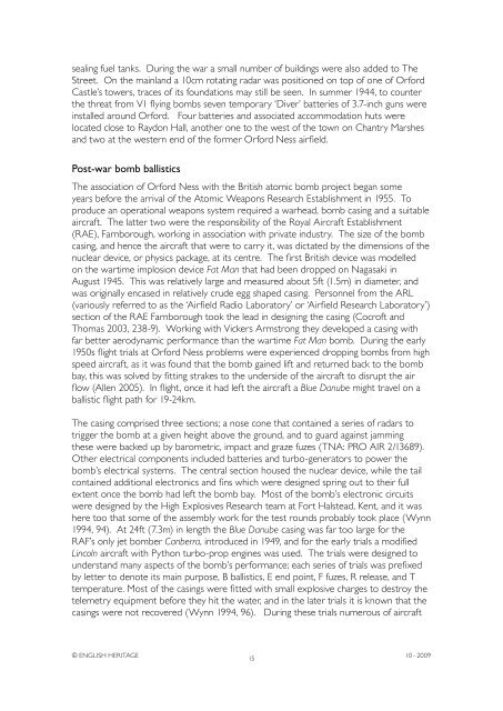
sealing fuel tanks. During the war a small number of buildings were also added to The<br />
Street. On the mainland a 10cm rotating radar was positioned on top of one of <strong>Orford</strong><br />
Castle’s towers, traces of its foundations may still be seen. In summer 1944, to counter<br />
the threat from V1 flying bombs seven temporary ‘Diver’ batteries of 3.7-inch guns were<br />
installed around <strong>Orford</strong>. Four batteries and associated accommodation huts were<br />
located close to Raydon Hall, another one to the west of the town on Chantry Marshes<br />
and two at the western end of the former <strong>Orford</strong> Ness airfield.<br />
Post-war bomb ballistics<br />
The association of <strong>Orford</strong> Ness with the British atomic bomb project began some<br />
years before the arrival of the <strong>Atomic</strong> <strong>Weapons</strong> <strong>Research</strong> <strong>Establishment</strong> in 1955. To<br />
produce an operational weapons system required a warhead, bomb casing and a suitable<br />
aircraft. The latter two were the responsibility of the Royal Aircraft <strong>Establishment</strong><br />
(RAE), Farnborough, working in association with private industry. The size of the bomb<br />
casing, and hence the aircraft that were to carry it, was dictated by the dimensions of the<br />
nuclear device, or physics package, at its centre. The first British device was modelled<br />
on the wartime implosion device Fat Man that had been dropped on Nagasaki in<br />
August 1945. This was relatively large and measured about 5ft (1.5m) in diameter, and<br />
was originally encased in relatively crude egg shaped casing. Personnel from the ARL<br />
(variously referred to as the ‘Airfield Radio Laboratory’ or ‘Airfield <strong>Research</strong> Laboratory’)<br />
section of the RAE Farnborough took the lead in designing the casing (Cocroft and<br />
Thomas 2003, 238-9). Working with Vickers Armstrong they developed a casing with<br />
far better aerodynamic performance than the wartime Fat Man bomb. During the early<br />
1950s flight trials at <strong>Orford</strong> Ness problems were experienced dropping bombs from high<br />
speed aircraft, as it was found that the bomb gained lift and returned back to the bomb<br />
bay, this was solved by fitting strakes to the underside of the aircraft to disrupt the air<br />
flow (Allen 2005). In flight, once it had left the aircraft a Blue Danube might travel on a<br />
ballistic flight path for 19-24km.<br />
The casing comprised three sections; a nose cone that contained a series of radars to<br />
trigger the bomb at a given height above the ground, and to guard against jamming<br />
these were backed up by barometric, impact and graze fuzes (TNA: PRO AIR 2/13689).<br />
Other electrical components included batteries and turbo-generators to power the<br />
bomb’s electrical systems. The central section housed the nuclear device, while the tail<br />
contained additional electronics and fins which were designed spring out to their full<br />
extent once the bomb had left the bomb bay. Most of the bomb’s electronic circuits<br />
were designed by the High Explosives <strong>Research</strong> team at Fort Halstead, Kent, and it was<br />
here too that some of the assembly work for the test rounds probably took place (Wynn<br />
1994, 94). At 24ft (7.3m) in length the Blue Danube casing was far too large for the<br />
RAF’s only jet bomber Canberra, introduced in 1949, and for the early trials a modified<br />
Lincoln aircraft with Python turbo-prop engines was used. The trials were designed to<br />
understand many aspects of the bomb’s performance; each series of trials was prefixed<br />
by letter to denote its main purpose, B ballistics, E end point, F fuzes, R release, and T<br />
temperature. Most of the casings were fitted with small explosive charges to destroy the<br />
telemetry equipment before they hit the water, and in the later trials it is known that the<br />
casings were not recovered (Wynn 1994, 96). During these trials numerous of aircraft<br />
© ENGLISH HERITAGE<br />
15<br />
10 - 2009


