EZ Load Cargo Gate Installation Instructions - RealTruck.com
EZ Load Cargo Gate Installation Instructions - RealTruck.com
EZ Load Cargo Gate Installation Instructions - RealTruck.com

You also want an ePaper? Increase the reach of your titles
YUMPU automatically turns print PDFs into web optimized ePapers that Google loves.
ASSEMBLY INSTRUCTIONS AND WARRANTY INFORMATION<br />
FOR E-Z LOAD RUFF N’ TUFF HEAVY DUTY CARGO GATE<br />
Tools needed for assembly and installation: Tape Measure; Marker; Phillips Screwdriver, Drill or Driver<br />
with #2 Phillips Head Bit; Hack Saw, Allen Wrench (provided).<br />
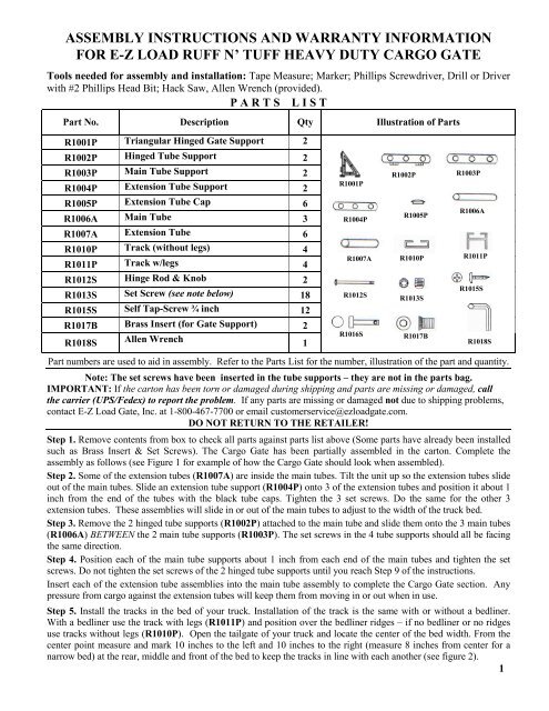
P A R T S L I S T<br />
Part No. Description Qty Illustration of Parts<br />
R1001P Triangular Hinged <strong>Gate</strong> Support 2<br />
R1002P Hinged Tube Support 2<br />
R1003P Main Tube Support 2<br />
R1004P Extension Tube Support 2<br />
R1005P Extension Tube Cap 6<br />
R1006A Main Tube 3<br />
R1007A Extension Tube 6<br />
R1010P Track (without legs) 4<br />
R1011P Track w/legs 4<br />
R1012S Hinge Rod & Knob 2<br />
R1013S Set Screw (see note below) 18<br />
R1015S Self Tap-Screw ¾ inch 12<br />
R1017B Brass Insert (for <strong>Gate</strong> Support) 2<br />
R1018S Allen Wrench 1<br />
R1001P<br />
R1004P<br />
R1002P<br />
R1005P<br />
R1003P<br />
R1006A<br />
R1007A R1010P R1011P<br />
R1012S<br />
R1016S<br />
R1013S<br />
R1017B<br />
R1015S<br />
R1018S<br />
Part numbers are used to aid in assembly. Refer to the Parts List for the number, illustration of the part and quantity.<br />
Note: The set screws have been inserted in the tube supports – they are not in the parts bag.<br />
IMPORTANT: If the carton has been torn or damaged during shipping and parts are missing or damaged, call<br />
the carrier (UPS/Fedex) to report the problem. If any parts are missing or damaged not due to shipping problems,<br />
contact E-Z <strong>Load</strong> <strong>Gate</strong>, Inc. at 1-800-467-7700 or email customerservice@ezloadgate.<strong>com</strong>.<br />
DO NOT RETURN TO THE RETAILER!<br />
Step 1. Remove contents from box to check all parts against parts list above (Some parts have already been installed<br />
such as Brass Insert & Set Screws). The <strong>Cargo</strong> <strong>Gate</strong> has been partially assembled in the carton. Complete the<br />
assembly as follows (see Figure 1 for example of how the <strong>Cargo</strong> <strong>Gate</strong> should look when assembled).<br />
Step 2. Some of the extension tubes (R1007A) are inside the main tubes. Tilt the unit up so the extension tubes slide<br />
out of the main tubes. Slide an extension tube support (R1004P) onto 3 of the extension tubes and position it about 1<br />
inch from the end of the tubes with the black tube caps. Tighten the 3 set screws. Do the same for the other 3<br />
extension tubes. These assemblies will slide in or out of the main tubes to adjust to the width of the truck bed.<br />
Step 3. Remove the 2 hinged tube supports (R1002P) attached to the main tube and slide them onto the 3 main tubes<br />
(R1006A) BETWEEN the 2 main tube supports (R1003P). The set screws in the 4 tube supports should all be facing<br />
the same direction.<br />
Step 4. Position each of the main tube supports about 1 inch from each end of the main tubes and tighten the set<br />
screws. Do not tighten the set screws of the 2 hinged tube supports until you reach Step 9 of the instructions.<br />
Insert each of the extension tube assemblies into the main tube assembly to <strong>com</strong>plete the <strong>Cargo</strong> <strong>Gate</strong> section. Any<br />
pressure from cargo against the extension tubes will keep them from moving in or out when in use.<br />
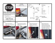
Step 5. Install the tracks in the bed of your truck. <strong>Installation</strong> of the track is the same with or without a bedliner.<br />
With a bedliner use the track with legs (R1011P) and position over the bedliner ridges – if no bedliner or no ridges<br />
use tracks without legs (R1010P). Open the tailgate of your truck and locate the center of the bed width. From the<br />
center point measure and mark 10 inches to the left and 10 inches to the right (measure 8 inches from center for a<br />
narrow bed) at the rear, middle and front of the bed to keep the tracks in line with each another (see figure 2).<br />
1 1
Step 6. Set 2 pieces of track on the marks on one side and check the length. If the tracks are longer than the bed,<br />
mark the correct length (at least 1 inch inside the tailgate) and cut with hacksaw. Do the same for the other side.<br />
Starting at the front of the bed screw the first track down with 3 - ¾”screws (R1015S). Note: Use a screwdriver to<br />
tighten the screws into the bedliner to prevent stripping the threads. Now slide the <strong>Gate</strong> Support (R1001P) on the<br />
installed track and place the second piece of track on the marks butted tightly against the front track. Slide the <strong>Gate</strong><br />
Support an inch onto the rear track so it holds the butted track ends in alignment, then screw the second piece of<br />
track in place starting at rear and working towards the front (see figure 3). Repeat for the other side.<br />
Step 7. Remove both <strong>Gate</strong> Supports (R1001P) from the tracks. Take the brass inserts (R1017B) and press them<br />
into the holes on the bottom of the <strong>Gate</strong> Supports, round end first (see figure 4). The inserts will be drawn tightly<br />
into the hex-sided hole when you turn the hinge rods to the right to secure the gate to the track. If the inserts <strong>com</strong>e<br />
out, use a clear silicone glue to hold them in place. Some units have the inserts pre-installed.<br />
Step 8. Slide the <strong>Gate</strong> Supports into the tracks with the hinged side facing you. Place the main <strong>Cargo</strong> <strong>Gate</strong><br />
assembly from Step 4 with the tube support hinges on TOP of the gate support hinges and insert the Hinge Rods<br />
down through both hinges. Turn the knobs to the right to screw the hinge rods into the inserts (see figure 5).<br />
Step 9. Turn the knobs on the hinge rods to the right to secure the gate to the track, center the gate assembly, then<br />
align the 2 hinged tube supports vertically, and tighten the 6 set screws on the hinged tube supports (see figure 6).<br />
Now your E-Z <strong>Load</strong> <strong>Cargo</strong> <strong>Gate</strong> is installed and ready for use. To operate, loosen the knobs (turn to left)<br />
and slide the <strong>Gate</strong> to the position desired and tighten the knobs (turn to right). DO NOT OVER TIGHTEN!<br />
Slide the end extension units in or out of the Center <strong>Cargo</strong> <strong>Gate</strong> to adjust the <strong>Gate</strong> width to your truck bed<br />
width. The hinge design allows the <strong>Cargo</strong> <strong>Gate</strong> to be positioned on an angle. Any pressure against the<br />
extension units will keep them in place when in use.<br />
Figure 1<br />
<strong>Cargo</strong> <strong>Gate</strong> Assembly<br />
Figure 2<br />
Install Tracks – Narrow Beds 8” from<br />
Center, Full Size Beds 10” from Center<br />
Figure 3<br />
Use <strong>Gate</strong> Support to Align Tracks at<br />
Joint and Screw in Place (Tighten<br />
screws by hand with bedliner to avoid<br />
stripping threads)<br />
Figure 4<br />
Press Brass Insert in Bottom of <strong>Gate</strong><br />
Support with Hex End Aligned with<br />
Hex Hole. Insert will be drawn in tight<br />
when knob is turned to right to secure<br />
to track. Use clear silicone glue if insert<br />
<strong>com</strong>es out.<br />
Figure 5<br />
Use Hinge Rods to Connect <strong>Gate</strong><br />
Assembly to <strong>Gate</strong> Supports<br />
Figure 6<br />
Align Tube Supports Straight Up<br />
And Tighten Set Screws<br />
2