
Create successful ePaper yourself
Turn your PDF publications into a flip-book with our unique Google optimized e-Paper software.
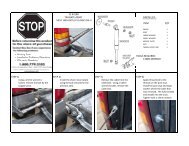
Before returning this product<br />
to the store of purchase<br />
Contact Dee Zee if you experience the following problems:<br />
• Missing Parts<br />
• Installation Problems/Questions<br />
• Warranty Questions<br />
1.800.779.2102<br />
Hours of operation: 8am - 5pm CST, Mon-Friday<br />
Review <strong>com</strong>plete warranty policy and register your product at:<br />
www.deezee.<strong>com</strong>
Dee Zee Running Board Installation Instructions<br />
Congratulations on your purchase of a quality Dee Zee product. Dee Zee is<br />
recognized as having the highest quality running boards and accessories on<br />
the market today. We have earned this reputation by offering our customers<br />
a product they can be proud to place on their vehicles. Dee Zee meets all<br />
the criteria of manufacturing a custom-fit product which guarantees it to<br />
be the easiest product to install.<br />
Note: Please take time to read all of the instructions before beginning this installation.<br />
War ning! Please check for wiring or other obstructions before drilling any holes into<br />
the vehicle. If it is necessar y to drill any holes into the vehicle, Dee Zee re<strong>com</strong>mends<br />
putting a sealant or rust inhibitor around all holes drilled into the body of the vehicle.<br />
War ning! It is the sole responsibility of the vehicle owner to check for tire clearance.<br />
War ning! It is unlawful and dangerous to ride on running boards or side box boards<br />
while the vehicle is in motion.<br />
Cleaning Instructions: To maintain the bright finish of your Dee Zee running boards,<br />
clean with a mild detergent. For our stainless steel products and accessories, the<br />
application of a high grade automotive type wax is re<strong>com</strong>mended.<br />
If you should happen to have any questions with this product or you have an<br />
installation question, please feel free to call us at:<br />
1-800-779-8222<br />
If you would like to find out more infor mation on Dee Zee’s products please<br />
feel free to visit our website at:<br />
WWW.DEEZEE.COM
Dee Zee Brite Tread Running Board Installation Instruction<br />
<strong>DZ</strong> <strong>1358</strong> / <strong>DZ</strong> 1359 (1999 - Current) Chevy 6'/8' Box Pickup<br />
SIDE BOX BOARD BULB SEAL GASKET MUD FLAP LEFT BRACKET<br />
A B C D<br />
BD 1348 L/R<br />
GSK-15<br />
BD 1349 L/R X2 GSK-41 4 FT./6.25 FT. MUDFLAP 1 LH / 1 RH B 1648LP X2<br />
E<br />
RIGHT BRACKET SUPPORT BRACKET<br />
1/4 X 1" RIBNECK 1/4" FLAT WASHER<br />
F G<br />
CARRIAGE BOLT<br />
H<br />
B 1648RP X2 B 1382N X2 PN 87 X8 PN 310 X 16<br />
1/4" HEX NUT SHEET<br />
1/4 X 3/4" HEX<br />
3/8 X 1 1/4" HEX<br />
I J<br />
METAL SCREW<br />
K<br />
HEAD BOLT<br />
L<br />
HEAD BOLT<br />
PN 71 X16 PN 97B X4 PN 70 X4 PN 114B X 2<br />
3/8" FLAT WASHER<br />
3/8" THREADED<br />
1/4 X 1 1/4" HEX<br />
1/4" FENDER<br />
M<br />
N<br />
PLATE<br />
O<br />
HEAD BOLT<br />
P<br />
WASHER<br />
PN 113B X2 PN 407 X2 PN 78 X4 PN 265 X4<br />
1/4 X 1" HEX 1/4" FLAT WASHER<br />
1/4" HEX NUT<br />
9" ANGLE BRACE<br />
Q<br />
HEAD BOLT<br />
R<br />
BLACK<br />
S<br />
BLACK<br />
T<br />
BLACK<br />
PN 96B X8 PN 848-CHY X16 PN 71B X8 B 865 X4<br />
BENT SPACER 8mm X 40mm BOLT<br />
8mm WASHER<br />
U V W<br />
PHB196 X4 PN 836 X2 PN 325 X2<br />
<strong>DZ</strong> <strong>1358</strong> 1 OF 16 6/6/2011
TOOLS REQUIRED<br />
TIN SNIPS<br />
WRENCH/RATCHET<br />
3/8", 7/16", 9/16" TAPE<br />
13mm, 18mm<br />
MEASURE<br />
1<br />
3/16" 1/4" DRILL BIT<br />
PHILLIPS SCREWDRIVER<br />
Secure mudflap [C] to running board [A] using 1/4 x 3/4" hex head bolts [K], 1/4" flat washers [H], and<br />
1/4" hex nuts [I]. Tighten into place using a 7/16" wrench/socket.<br />
Place bulb-seal gasket [B] onto the back lip of the running board and trim the gasket to the board<br />
length using the tin snips.<br />
<strong>DZ</strong> <strong>1358</strong> 2 OF 16 6/6/2011
2<br />
The installation of the board brackets will vary depending on the model year of the vehicle.<br />
On the following pages, find the appropriate section for your model year and follow the installtion<br />
instructions. If your vehicle does not match the photos, there may be some model year crossover features.<br />
If your vehicle model year is at the start or end of a model year change, you may need to use the previous<br />
(or next) model year section. Once the bracket are installed, proceed to STEP #.<br />
1999 -2007 Driver Side Front Brace<br />
Locate the front sub-box support as shown below. Remove the factory bolt holding the frame to<br />
the bottom of the sub-box support using an 18mm socket and ratchet.<br />
<strong>DZ</strong> <strong>1358</strong> 3 OF 16 6/6/2011
1999 -2007 Driver Side Front Brace (continued)<br />
Place the support bracket [F] into the sub-box support.<br />
Attach the support bracekt to the sub-floor support using a 1/4 x 1 1/4" hex head bolt [O] and a 1/4"<br />
fender washer [P] where shown in the photo on the right.<br />
Attach the LH running board brace [D] using the factory bolt previously removed<br />
and a 1/4 x 1 1/4" hex head bolt [O] and a 1/4" fender washer [P].<br />
Tighten the factory bolt using an 18mm socket. Tighten the 1/4" bolts using a 7/16" wrench or socket.<br />
<strong>DZ</strong> <strong>1358</strong> 4 OF 16 6/6/2011
1999 -2007 Driver Side Rear Brace<br />
Locate the rear sub-box support as shown below. Remove the factory bolt holding the frame to<br />
the bottom of the sub-box support using an 18mm socket and ratchet.<br />
<strong>DZ</strong> <strong>1358</strong> 5 OF 16 6/6/2011
1999 -2007 Driver Side Rear Brace<br />
Place the left mounting bracket [D] up to the sub-box support and attach using the factory bolt<br />
previously removed.<br />
Place a 3/8 x 1 1/4" hex head bolt [L] and 3/8" washer [M] up through the other hole in the mounting<br />
bracket and thread into the 3/8" threaded plate [N].<br />
Tighten the factory bolt using an 18mm socket. Tighten the 3/8" bolt using a 9/16" wrench or socket.<br />
<strong>DZ</strong> <strong>1358</strong> 6 OF 16 6/6/2011
2007 - 2010 Driver Side Front Brace<br />
Locate the front sub-box support as shown below. Remove the factory bolt holding the frame to<br />
the bottom of the sub-box support using an 18mm socket and ratchet.<br />
<strong>DZ</strong> <strong>1358</strong> 7 OF 16 6/6/2011
2007 - 2010 Driver Side Front Brace (continued)<br />
Place a 3/8" threaded plate [N] into the end of the sub-box support and align with the hole.<br />
Put the left hand mounting bracket [D] up to the sub-box support and attach using the previously removed<br />
factory bolt. Attach the other end of the bracket using a 3/8 x 1 1/4" hex head bolt [L] and<br />
3/8" flat washer [M] into the threaded plate.<br />
Tighten the factory bolt using an 18mm socket. Tighten the 3/8" bolt using a 9/16" wrench or socket.<br />
<strong>DZ</strong> <strong>1358</strong> 8 OF 16 6/6/2011
2007 - 2010 Driver Side Rear Brace<br />
Locate the rear sub-box support as shown below. Remove the factory bolt holding the frame to<br />
the bottom of the sub-box support using an 18mm socket and ratchet.<br />
<strong>DZ</strong> <strong>1358</strong> 9 OF 16 6/6/2011
2007 - 2010 Driver Side Rear Brace (continued)<br />
Place the support bracket [F] into the sub-box support. Attach using a 1/4 x 1 1/4" hex head bolt [O] and<br />
1/4" fender washer [P] through the sub-floor support into the support bracket.<br />
Attached the mounting bracket [D] using the previously removed factory bolt<br />
and a 1/4 x 1 1/4" hex head bolt [O] and a 1/4" fender washer [P].<br />
Tighten the factory bolt using an 18mm socket. Tighten the 1/4" bolts using a 7/16" wrench or socket.<br />
<strong>DZ</strong> <strong>1358</strong> 10 OF 16 6/6/2011
2010 - Current Driver Side Front Brace<br />
Locate the rear sub-box support as shown below. Remove the factory bolt holding the frame to<br />
the bottom of the sub-box support using an 18mm socket and ratchet.<br />
Remove the bolt at the front of the sub-floor support using a 13mm socket and ratchet.<br />
13mm<br />
18mm<br />
Put the left hand mounting bracket [D] up to the sub-box support and attach using the previously removed<br />
factory bolts. If the white plastic tab interferes with the brace, if may be trimmed to allow the brace to fit.<br />
Tighten the factory bolt using an 18mm socket. Tighten the 8mm bolt using a 13mm wrench or socket.<br />
<strong>DZ</strong> <strong>1358</strong> 11 OF 16 6/6/2011
2010 - Current Driver Side Rear Brace<br />
Locate the rear sub-box support as shown below. Remove the factory bolt holding the frame to<br />
the bottom of the sub-box support using an 18mm socket and ratchet.<br />
Attach the mounting bracket [D] using the previously removed factory bolt, but don't tighten <strong>com</strong>pletely.<br />
<strong>DZ</strong> <strong>1358</strong> 12 OF 16 6/6/2011
2010 - Current Driver Side Rear Brace (continued)<br />
Put the 8mm bolt [V] through the 8mm washer [W] and a bent spacer [U], then put the bolt through<br />
the slot in the brace, and through another bent spacer [U] on the top of the brace. Thread the 8mm<br />
bolt into the weld nut on the sub-floor support.<br />
Tighten the factory bolt using an 18mm socket. Tighten the 8mm bolt using a 13mm wrench or socket.<br />
<strong>DZ</strong> <strong>1358</strong> 13 OF 16 6/6/2011
3<br />
Attach the angle brace [T] to the main upright braces using the 1/4" x 1" hex head bolt [Q],<br />
the 1/4" flat washer [R], and the 1/4" hex nut [S]. The driver side rear bracket is shown below.<br />
The angle braces [T] on the front and rear main brace should be pointing towards each other.<br />
Secure the angle braces in place, but do not tighten <strong>com</strong>pletely.<br />
<strong>DZ</strong> <strong>1358</strong> 14 OF 16 6/6/2011
4<br />
Place the side box board on the angle braces. Align the side box board with the cab board.<br />
Adjust the angle braces [T] as needed to align the step surface of the side box board with the<br />
step surface of the cab board. Tighten the angle braces in place using a 7/16" wrench and socket.<br />
Once the board is straight with the cab board, drill 1/4" holes up through the board using<br />
the 1st and 3rd slots in the braces as location guides.<br />
5<br />
Attach the running board to the angle brace using the 1/4" x 1" ribneck carriage bolt [G],<br />
1/4" flat washer [H], and 1/4" hex nut [I]. Tighten using a 7/16" wrench or deep well socket.<br />
<strong>DZ</strong> <strong>1358</strong> 15 OF 16 6/6/2011
6<br />
Pressing the flap up against the wheel well opening, drill two 3/16" holes through the mudflap and<br />
the sheet metal of the wheel well. Secure the flap using the sheet metal screw [J] with a 3/8"<br />
socket or wrench.<br />
Repeat the assembly steps for the other side of the vehicle.<br />
<strong>DZ</strong> <strong>1358</strong> 16 OF 16 6/6/2011