EZ Load Gate Bed Extender Installation Instructions - RealTruck.com
EZ Load Gate Bed Extender Installation Instructions - RealTruck.com
EZ Load Gate Bed Extender Installation Instructions - RealTruck.com

Create successful ePaper yourself
Turn your PDF publications into a flip-book with our unique Google optimized e-Paper software.
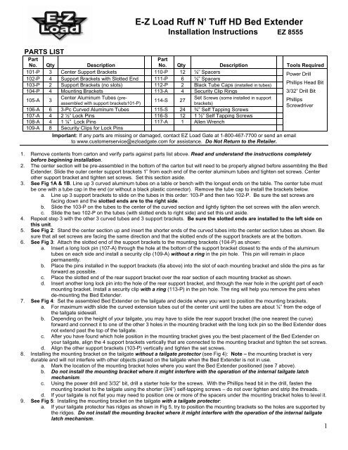
E-Z <strong>Load</strong> Ruff N’ Tuff HD <strong>Bed</strong> <strong>Extender</strong><br />
<strong>Installation</strong> <strong>Instructions</strong> <strong>EZ</strong> 8555<br />
PARTS LIST<br />
Part<br />
Part<br />
No. Qty Description Tools Required<br />
No. Qty Description<br />
101-P 3 Center Support Brackets 110-P 12 ¼” Spacers<br />
102-P 4 Support Brackets with Slotted End 111-P 6 ½” Spacers<br />
103-P 2 Support Brackets (no slots) 112-P 2 Black Tube Caps (installed in tubes)<br />
104-P 4 Mounting Brackets 113-A 4 Security Clip Rings<br />
105-A 3<br />
Center Aluminum Tubes (preassembled<br />
with support brackets101-P)<br />
114-S 27<br />
Set Screws (some installed in support<br />
brackets)<br />
106-A 6 3-Pc Curved Aluminum Tubes 115-S 24 ¾” Self Tapping Screws<br />
107-A 4 2 ½” Lock Pins 116-S 12 1 ½” Self Tapping Screws<br />
108-A 4 1 ¼” Lock Pins 117-A 1 Allen Wrench<br />
109-A 8 Security Clips for Lock Pins<br />
Important: If any parts are missing or damaged, contact <strong>EZ</strong> <strong>Load</strong> <strong>Gate</strong> at 1-800-467-7700 or send an email<br />
to www.customerservice@ezloadgate.<strong>com</strong> for assistance. Do Not Return to the Retailer.<br />
Power Drill<br />
Phillips Head Bit<br />
3/32” Drill Bit<br />
Phillips<br />
Screwdriver<br />
1. Remove contents from carton and verify parts against parts list above. Read and understand the instructions <strong>com</strong>pletely<br />
before beginning installation.<br />
2. The center section will be pre-assembled in the bottom of the carton but will need to be properly aligned before assembling the <strong>Bed</strong><br />
<strong>Extender</strong>. Slide the outer center support brackets 1” from each end of the center aluminum tubes and tighten set screws. Center<br />
other support bracket and tighten set screws. Set this section aside.<br />
3. See Fig 1A & 1B. Line up 3 curved aluminum tubes on a table or bench with the longest ends on the table. The center tube must<br />
be one with a tube cap in the end (or without a black plastic connector). Remove the tube cap to install the brackets below.<br />
a. Line up 3 support brackets to slide on the tubes in this order: 103-P and then two 102-P. Be sure the set screws are<br />
facing down and the slotted ends are to the right side.<br />
b. Slide the 103-P on the tubes to the center of the curved section and lightly tighten the set screws with the allen wrench.<br />
c. Slide the two 102-P on the tubes (with slotted ends to right side) and set this unit aside.<br />
4. Repeat step 3 with the other 3 curved tubes and 3 support brackets. Be sure the slotted ends are installed to the left side on<br />
this unit.<br />
5. See Fig 2: Stand the center section up and insert the shorter ends of the curved tubes into the center section tubes as shown. Be<br />
sure that all set screws are facing the same direction and that the slotted ends of the support brackets are at the bottom.<br />
6. See Fig 3: Attach the slotted end of the support brackets to the mounting brackets (104-P) as shown:<br />
a. Insert a long lock pin (107-A) through the hole at the bottom of the support bracket closest to the ends of the aluminum<br />
tubes on each side and install a security clip (109-A) without a ring in the pin hole. This pin will remain in place<br />
permanently.<br />
b. Place the pins installed in the support brackets (6a above) into the slot of each mounting bracket and slide the pins as far<br />
forward as possible.<br />
c. Place the slotted end of the rear support bracket over the rear section of each mounting bracket as shown.<br />
d. Insert another long lock pin into the hole of the rear support bracket, and through the rear hole in the upright part of each<br />
mounting bracket. Install a security clip with a ring (113-P) in the pin hole. The ring will help you remove the pins when<br />
de-mounting the <strong>Bed</strong> <strong>Extender</strong>.<br />
7. See Fig 4: Set the assembled <strong>Bed</strong> <strong>Extender</strong> on the tailgate and decide where you want to position the mounting brackets.<br />
a. For maximum width slide the curved extension tubes out of the center unit until the tubes are about ¼” from the edge of<br />
the tailgate sidewall.<br />
b. Depending on the height of your tailgate, you may have to slide the rear support bracket (the one nearest the curve)<br />
forward and connect it to one of the other 3 holes in the mounting bracket with the long lock pin so the <strong>Bed</strong> <strong>Extender</strong> does<br />
not extend past the top of the tailgate.<br />
c. After you have found which hole position in the mounting bracket gives you the best placement of the <strong>Bed</strong> <strong>Extender</strong> on<br />
your tailgate, align the 4 support brackets vertically that are connected to the mounting bracket and tighten the set screws.<br />
d. Align the other support brackets (103-P) vertically and tighten the set screws.<br />
8. Installing the mounting bracket on the tailgate without a tailgate protector (see Fig 4): Note – the mounting bracket is very<br />
durable and will not interfere with other objects placed on the tailgate when the <strong>Bed</strong> <strong>Extender</strong> is not in use.<br />
a. Mark the location of the mounting bracket holes where you want the <strong>Bed</strong> <strong>Extender</strong> positioned (see 7 above).<br />
b. Do not install the mounting bracket where it might interfere with the operation of the internal tailgate latch<br />
mechanism.<br />
c. Using the power drill and 3/32” bit, drill a starter hole for the screws. With the Phillips head bit in the drill, fasten the<br />
mounting bracket to the tailgate using the shorter (3/4”) self-tapping screws – do not over tighten and strip the threads.<br />
d. If your tailgate is not flat you may need to position one or more of the spacers under the mounting bracket holes to level it.<br />
9. See Fig 5: Installing the mounting bracket on the tailgate with a tailgate protector:<br />
a. If your tailgate protector has ridges as shown in Fig 5, try to position the mounting brackets so the holes are supported by<br />
the ridges. Do not install the mounting bracket where it might interfere with the operation of the internal tailgate<br />
latch mechanism.<br />
1
. Mark the hole positions, drill a starter hole with the drill bit and fasten the mounting brackets to the tailgate using the<br />
longer (1 ½”) self-tapping screws. The screws need to penetrate the surface of the tailgate to secure the mounting<br />
brackets.<br />
10. See Fig 6: If the placement of the <strong>Bed</strong> <strong>Extender</strong> is such that the mounting bracket holes are not supported by the tailgate protector<br />
ridges, use the small or large spacers to level the mounting bracket.<br />
a. Mark the hole positions, drill a starter hole with the drill bit and fasten the mounting brackets to the tailgate using the<br />
longer (1 ½”) self-tapping screws. Do not over tighten and strip the threads. The screws need to penetrate the surface of<br />
the tailgate to secure the mounting bracket.<br />
11. To connect the <strong>Bed</strong> <strong>Extender</strong> to the mounting bracket, place the front support brackets with the permanent lock pins into the slot of<br />
the mounting brackets, slide it all the way forward, lower the rear support brackets over the mounting brackets and insert the other<br />
lock pins through the rear support brackets and the mounting bracket holes and insert the security clips with rings in the pin holes.<br />
Reverse this procedure to remove the <strong>Bed</strong> <strong>Extender</strong>.<br />
12. See Fig 7: Mounting the <strong>Bed</strong> <strong>Extender</strong> to the front panel of the truck bed. This is an optional connection point for your <strong>Bed</strong><br />
<strong>Extender</strong> to provide a secure cargo storage area inside the truck bed.<br />
a. Remove the <strong>Bed</strong> <strong>Extender</strong> from the tailgate mounting bracket.<br />
b. Insert one of the 1 ¼” lock pins (108-A) in the holes of each of the black plastic connectors at the end of the BOTTOM<br />
curved extension tubes and install a security clip (109-A) without a ring in the pin hole. This pin will remain in place<br />
permanently.<br />
c. Take the other 2 mounting brackets, place the pins installed in the connectors into the slot of the mounting bracket and<br />
connect the other end of the mounting bracket to the connectors in the TOP curved extension tubes using the other 1 ¼”<br />
lock pins.<br />
d. Install the security clips with a ring in the lock pin holes.<br />
e. Position the <strong>Bed</strong> <strong>Extender</strong> with the mounting brackets up to the front panel of the truck bed. Slide the telescoping<br />
extension tubes in or out to the width that you want for the storage area.<br />
f. Mark the location of the mounting bracket holes.<br />
g. If you have a bed liner with ridges, line up the mounting bracket holes so the screws will screw directly into the ridges.<br />
Using the ¾” self-tapping screws fasten the mounting brackets to the bed liner. Do not over tighten and strip the threads.<br />
h. If you are fastening the mounting bracket directly to the truck bed front panel, after marking the hole locations, drill a<br />
starter hole with the 3/32” bit and fasten the mounting bracket with the ¾” self-tapping screws. Do not over tighten and<br />
strip the threads.<br />
13. To connect the <strong>Bed</strong> <strong>Extender</strong> to the front panel mounting brackets, slide the pins in the connectors in the bottom extension tubes in<br />
the slots of the mounting brackets. Fasten the connectors in the top extension tubes to the mounting brackets with the lock pins<br />
and insert the security pins in the lock pin holes. To remove the <strong>Bed</strong> <strong>Extender</strong> reverse this procedure.<br />
Important Note: The E-Z <strong>Load</strong> Ruff N’ Tuff <strong>Bed</strong> <strong>Extender</strong> is sold as a decorative accessory and should<br />
not be relied upon solely as protection for the vehicle, occupants or cargo.<br />
E-Z LOAD GATE, INC.<br />
LIMITED LIABILITY WARRANTY AND DISCLAIMER<br />
E-Z LOAD GATE, INC. (<strong>com</strong>pany) warrants this product to be free of original defects in materials or workmanship as long<br />
as the original owner purchaser owns the motor vehicle in which it is installed. This warranty does not cover damage<br />
resulting from accident, misuse or abuse, neglect, lack of reasonable care, improper installation or normal wear and tear.<br />
The <strong>com</strong>pany will repair or replace, at its option, any product covered by this warranty that be<strong>com</strong>es defective. This is a<br />
parts-only warranty and such repair or replacement shall be the <strong>com</strong>pany’s sole obligation and the customer’s sole<br />
remedy for a defective product. The <strong>com</strong>pany shall have no liability for personal or animal injury, property damage, or any<br />
incidental or consequential damages of any kind or nature. THE FOREGOING WARRANTIES ARE EXCLUSIVE AND IN<br />
LIEU OF ALL OTHER WARRANTIES, EXPRESSED OR IMPLIED, AND THE COMPANY DISCLAIMS ALL OTHER<br />
WARRANTIES, EXPRESSED OR IMPLIED, INCLUDING, WITHOUT LIMITATION, ANY IMPLIED WARRANTY OF<br />
MERCHANTABILITY OR FITNESS FOR A PARTICULAR PURPOSE.<br />
THIS WARRANTY IS VOID if the carrying capacity exceeds 200 pounds. Buyer assumes all risk and liability<br />
whatsoever from the installation and use of E-Z <strong>Load</strong> <strong>Gate</strong> products and/or accessories. E-Z <strong>Load</strong> <strong>Gate</strong> products<br />
and accessories are sold as decorative accessories and should not be relied upon solely as protection for the<br />
vehicle, occupants or cargo. E-Z <strong>Load</strong> <strong>Gate</strong>, Inc. assumes no liability for injury, loss, incidental or consequential<br />
damages in the event of a collision or roll over.<br />
To obtain warranty or repair service, contact E-Z <strong>Load</strong> <strong>Gate</strong>, Inc.<br />
EMAIL: customerservice@ezloadgate.<strong>com</strong><br />
PHONE: 1-800-467-7700<br />
2