Bestop Power Step Install Ford SuperDuty ... - RealTruck.com
Bestop Power Step Install Ford SuperDuty ... - RealTruck.com
Bestop Power Step Install Ford SuperDuty ... - RealTruck.com

Create successful ePaper yourself
Turn your PDF publications into a flip-book with our unique Google optimized e-Paper software.
TM<br />
Inc. ®<br />
<strong>Power</strong>step<br />
<strong>Install</strong>ation Instructions<br />
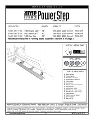
For: <strong>Ford</strong> F250/350 Regular Cab 1999 - 2004 (4 ft.) Part Number: 75102<br />
<strong>Ford</strong> F250/350 Supercab 1999 - 2004 (5 ft.) Part Number: 75103<br />
<strong>Ford</strong> F250/350 Crewcab 1999 - 2004 (6 ft.) Part Number: 75104<br />
<strong>Ford</strong> Excursion 2000 - 2004 (6 ft.)<br />
Part Number:75108<br />
75102/75103/75104/75108 pg 1<br />
Table of Contents<br />
POWERSTEP RUNNING BOARD PARTS LIST................. PAGE 2<br />
POWERSTEP RUNNING BOARD TOOLS NEEDED ............. PAGE 2<br />
POWERSTEP RUNNING BOARD INSTALLATION ............... PAGE 3<br />
POWERSTEP RUNNING BOARD WARRANTY ................. PAGE 8<br />
0305 Rev. A
Parts List and Hardware Identification<br />
<strong>Step</strong>, Qty - 2<br />
4 ft. 404.18<br />
5 ft. 404.19<br />
6 ft. 404.20<br />
Rear Arm, Qty - 2<br />
404.17 or<br />
404.44 (Excursion)<br />
Front Arm, Qty - 2<br />
404.16 or<br />
404.43 (Excursion)<br />
Hex Bolt, Qty - 8<br />
Phillips Head Bolt, Qty - 8<br />
Mounting Clip,<br />
Qty - 9<br />
Connecting Wire<br />
<strong>Install</strong>ation Tube, Qty - 1<br />
Washer Head Hex Bolt, Qty - 1<br />
Large Washer, Qty - 8<br />
Single Diode 404.10<br />
Harness, Qty - 4<br />
Double Diode 404.11<br />
Harness, Qty - 1<br />
Socket Head Bolt, Qty - 8<br />
Small Washer, Qty - 8<br />
Wiring Harness, 404.21<br />
Qty - 1<br />
Control Box, 404.42<br />
Qty - 1<br />
Red Butt Connector,<br />
Qty - 1<br />
Wire Ties, Qty - 25<br />
18 Gauge Connecting<br />
Wire, Qty - 2<br />
Tools Needed<br />
Tape Measure<br />
Flat Screwdriver<br />
Phillips Screwdriver<br />
13mm Wrench<br />
13mm Socket<br />
3/16" Allen Wrench<br />
Crimp Tool<br />
Wire Cutters<br />
Wire Strippers<br />
Safety Glasses<br />
75102/75103/75104/75108 pg 2<br />
0305 Rev. A
<strong>Install</strong>ation<br />
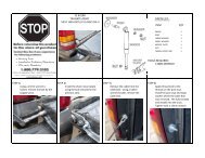
<strong>Step</strong> One<br />
INSTALL MOUNTING CLIPS - DRIVER’S SIDE<br />
Counting from the front, locate the second (2nd) and last set of mounting holes on the<br />
inner sill. Use a Hex Bolt and a Small Washer to install a Mounting Clip on each side of<br />
each hole. Do not tighten the bolts at this time.<br />
Rear<br />
Front<br />
Small<br />
Washers<br />
Hex Bolts<br />
Mounting<br />
Clips<br />
<strong>Step</strong> Two<br />
INSTALL ARMS - DRIVER’S SIDE<br />
Orient the Front and Rear Arms so<br />
the platforms face outside the vehicle<br />
to support the <strong>Step</strong> and with the<br />
motor on the Front Arm toward the<br />
front of the vehicle. Slip the notches<br />
in the Arms under the bolts and<br />
washers installed in <strong>Step</strong> One.<br />
Secure the bottom of the Arms with<br />
two Phillips Head Bolts and two<br />
Large Washers. Do not tighten the<br />
bolts yet.<br />
Repeat <strong>Step</strong>s One and Two on the<br />
passenger side of the vehicle.<br />
Large Washers<br />
Rear Arm<br />
Phillips Head<br />
Bolts<br />
Driver’s Side<br />
Driver’s Side<br />
View from under vehicle<br />
<strong>Step</strong> Three<br />
INSTALL STEPS<br />
Orient the <strong>Step</strong>s to the vehicle and align the holes in the <strong>Step</strong>s with the holes in the Arms.<br />
<strong>Install</strong> two Socket Head Bolts to secure the <strong>Step</strong> to each Arm. Use a 3/16" Allen Wrench to<br />
tighten the bolts to 10 ft./lbs.<br />
Tighten the bolts on the Arms to 16 ft./lbs. (22 Nm)<br />
<strong>Step</strong> Four<br />
INSTALL CONTROL BOX AND WIRING HARNESS<br />
Place the Control Box Mounting Clip over the flange on the Control Box so that the holes<br />
line up. Secure the assembly to the hole in the ledge in the engine <strong>com</strong>partment with the<br />
Washer Head Bolt from the parts kit. Use a 13mm Wrench to tighten the bolt to 5 ft./lbs<br />
(6.5 Nm).<br />
Attach the Wiring Harness to the Control Box.<br />
Washer Head Bolt<br />
Socket Head<br />
Bolts<br />
Wiring Harness<br />
Socket Head<br />
Bolts<br />
Control Box<br />
75102/75103/75104/75108 pg 3<br />
0305 Rev. A
<strong>Step</strong> Five<br />
WARNING<br />
REMOVE FUSE FROM WIRING HARNESS<br />
Remove the fuse from<br />
the Wiring Harness<br />
Remove the fuse from the Wiring Harness. Failure to do<br />
so could result in severe electrical shock which could<br />
harm the installer and/or damage the vehicle.<br />
Ground<br />
<strong>Step</strong> Six<br />
ATTACH WIRING HARNESS TO BATTERY<br />
Attach the ground wires on the Wiring Harness to<br />
the positive and negative terminals on the battery.<br />
Control Box<br />
Wiring Harness<br />
Secure to<br />
Battery<br />
<strong>Step</strong> Seven<br />
SECURE WIRING HARNESS<br />
Route the longer leg of the harness across the front of the engine<br />
<strong>com</strong>partment and down to the motor on the driver’s side step. Route the<br />
shorter leg to the motor on the passenger’s side step. Use the wire ties in<br />
the parts kit to secure the harness out of the way.<br />
Wiring<br />
Harness<br />
Wire<br />
Ties<br />
Battery<br />
<strong>Step</strong> Eight<br />
INSTALL TRIGGER WIRE<br />
Puncture the grommet in the<br />
firewall and thread the Trigger<br />
Wire from the Wiring Harness<br />
through the firewall.<br />
Puncture<br />
Grommet<br />
Trigger Wire - Thread<br />
through grommet<br />
Wire Tie<br />
<strong>Step</strong> Nine<br />
REMOVE STEP PLATE AND KICK PLATE - PASSENGER SIDE<br />
Open the passenger door. Remove the <strong>Step</strong> Plate and Kick Plate from the door<br />
opening and roll back the carpet to access the wiring underneath.<br />
Wire Tie<br />
Wiring Harness<br />
Remove <strong>Step</strong> Plate<br />
Remove Kick Plate<br />
Roll back Carpet<br />
75102/75103/75104/75108 pg 4<br />
0305 Rev. A
<strong>Step</strong> Ten<br />
INSTALL TWO SINGLE DIODE HARNESSES - PASSENGER SIDE<br />
Pull the Trigger Wire through the grommet in the firewall and<br />
connect, splicing as shown in the Wiring Diagram that applies to<br />
your vehicle.<br />
Connecting<br />
Wire<br />
Trigger<br />
Wire<br />
Trigger<br />
Wire<br />
Connecting<br />
Wire<br />
<strong>Step</strong> Eleven<br />
REMOVE DOOR BUTTON PANEL - DRIVER’S SIDE<br />
Use a flat screwdriver to pry up the button panel on<br />
the driver’s side door.<br />
<strong>Step</strong> Twelve<br />
DISCONNECT BUTTON PANEL - DRIVER’S SIDE<br />
Separate the connectors and remove the panel<br />
from the driver’s side door.<br />
<strong>Step</strong> Thirteen<br />
REMOVE DOOR LIGHT LENS - DRIVER’S SIDE<br />
Use a flat screwdriver to pry out the light lens on<br />
the driver’s side door.<br />
Use screwdriver to<br />
remove panel<br />
Separate<br />
Connectors<br />
75102/75103/75104/75108 pg 5<br />
0305 Rev. A
<strong>Step</strong> Fourteen<br />
REMOVE UPPER DOOR MOLDING - DRIVER’S SIDE<br />
Remove the upper door molding on the driver’s<br />
side door.<br />
<strong>Step</strong> Fifteen<br />
REMOVE SPEAKER SCREWS - DRIVER’S SIDE<br />
Remove the screws that attach the speaker<br />
to the driver’s side door.<br />
<strong>Step</strong> Sixteen<br />
INSTALL CONNECTING WIRE - DRIVER’S SIDE<br />
Pull back the molding on the door to access the wiring and splice the one Single Diode<br />
Harness and the Connecting Wire into position according to the wiring diagram that<br />
applies to your vehicle.<br />
Connecting<br />
Wire<br />
Single Diode<br />
Harness<br />
<strong>Step</strong> Seventeen<br />
THREAD CONNECTING WIRE - DRIVER’S SIDE<br />
Locate the plastic Connecting Wire <strong>Install</strong>ation Tube in the<br />
parts kit. Thread the tube into the hole in the door, through<br />
the openings in the door and into the vehicle. Then thread the<br />
Connecting Wire through the tube. Once the wire is in place,<br />
remove the tube.<br />
<strong>Step</strong> Eighteen<br />
REMOVE STEP PLATE AND KICK PLATE - DRIVER’S SIDE<br />
Open the passenger door. Remove the <strong>Step</strong> Plate and Kick Plate from the door<br />
opening and roll back the carpet to access the wiring underneath.<br />
Connecting Wire<br />
<strong>Install</strong>ation Tube<br />
Thread Tube into Vehicle<br />
Remove Kick Plate<br />
Remove <strong>Step</strong> Plate<br />
Connecting<br />
Wire - Thread<br />
through Tube<br />
To the Rear <strong>Step</strong><br />
Plate Wire<br />
Roll back Carpet<br />
75102/75103/75104/75108 pg 6<br />
0305 Rev. A
<strong>Step</strong> Nineteen<br />
INSTALL ONE DOUBLE DIODE AND ONE SINGLE DIODE HARNESS - DRIVER’S SIDE<br />
Pull the Trigger Wire through the grommet in the firewall and<br />
connect to harnesses, splicing as shown in the Wiring Diagram<br />
that applies to your vehicle.<br />
Connecting<br />
Wire<br />
Trigger<br />
Wire<br />
<strong>Step</strong> Twenty<br />
SECURE HARNESS - DRIVER’S SIDE<br />
Thread the plug end of the Wire Harness to the <strong>Step</strong><br />
Motor on the Driver’s Side and make sure that it is<br />
secured with wire ties.<br />
Wire Ties<br />
Wire Harness<br />
Detail of Single Diode Harness<br />
<strong>Step</strong> Twenty-One<br />
PLUG WIRING HARNESS INTO STEP MOTORS<br />
Plug the harness into the <strong>Step</strong> Motors on each side<br />
of the vehicle.<br />
Wiring<br />
Harness<br />
<strong>Step</strong> Twenty-Two<br />
REINSTALL FUSE<br />
Reinstall the fuse in the harness.<br />
CHECK STEP OPERATION<br />
Tip<br />
Before reassembling the driver’s side door,<br />
reinstall the fuse and reconnect the plugs to<br />
check that the <strong>Step</strong>s function properly.<br />
<strong>Step</strong> Twenty-Three<br />
Front Arm<br />
<strong>Step</strong><br />
Motor<br />
REASSEMBLE DRIVER DOOR<br />
Once you have checked that the <strong>Step</strong>s function<br />
properly, reassemble the driver’s side door and<br />
reinstall the Kick Plates and <strong>Step</strong> Plates on both<br />
sides of the vehicle.<br />
75102/75103/75104/75108 pg 7<br />
0305 Rev. A
<strong>Step</strong> Twenty-Four<br />
TEST DOORS<br />
Open the doors to make sure that the <strong>Step</strong><br />
drops into position on each side of the<br />
vehicle.<br />
Check that all bolts and fasteners are<br />
securely tightened.<br />
LIMITED WARRANTY<br />
We warrant our product to be free from defects in material and workmanship, for terms specified below, provided there has been normal use and proper maintenance. This warranty applies to<br />
the original purchaser only. All remedies under this warranty are limited to the repair or replacement of any item or items found by the factory to be defective within the time period specified.<br />
If you have a warranty claim, first you must call our factory at the number below for instructions. You must retain proof of purchase and submit a copy with any items returned for warranty<br />
work. Upon <strong>com</strong>pletion of warranty work, if any, we will return the repaired or replaced item or items to you freight prepaid. Damage to our products caused by accidents, fire, vandalism,<br />
negligence, misinstallation, misuse, Acts of God, or by defective parts not manufactured by us, is not covered under this warranty.<br />
THE WARRANTY TIME PERIOD IS AS FOLLOWS: ALL “HARD GOODS” MANUFACTURED BY OUR COMPANY (USING PRIMARILY VINYLS, PLASTICS, AND/OR FOAM): ONE YEAR FROM DATE<br />
OF PURCHASE.<br />
ANY IMPLIED WARRANTIES OF MERCHANTABILITY AND/OR FITNESS FOR A PARTICULAR PURPOSE CREATED HEREBY ARE LIMITED IN DURATION TO THE SAME DURATION AND SCOPE<br />
AS THE EXPRESS WRITTEN WARRANTY. OUR COMPANY SHALL NOT BE LIABLE FOR ANY INCIDENTAL OR CONSEQUENTIAL DAMAGE.<br />
Some states do not allow limitations on how long an implied warranty lasts, or the exclusion or limitation of incidental or consequential damages, so the above limitations or exclusions may not<br />
apply to you.<br />
This warranty gives you specific legal rights, and you may also have other rights which vary from state to state.<br />
For further information or request for warranty work, please contact:<br />
<strong>Bestop</strong> Inc.<br />
Customer Service<br />
(800)845-3567<br />
(303)465-1755<br />
75102/75103/75104/75108 pg 8<br />
0305 Rev. A