
You also want an ePaper? Increase the reach of your titles
YUMPU automatically turns print PDFs into web optimized ePapers that Google loves.
Rev 0
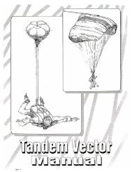
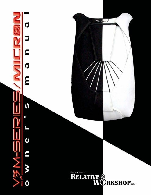
V E C T O R O W N E R ’ S M A N U A L<br />
Page • 2:88 09354 - 11/26/2003<br />
Rev 0
○ ○ ○ ○ ○ ○ ○ ○ ○ ○ ○ ○ ○ ○ ○ ○ ○ ○ ○ ○ ○ ○ ○ ○ ○ ○ ○ ○ ○ ○ ○ ○ ○ ○ ○ ○ ○ ○ ○ ○ ○ ○ ○ ○ ○ ○ ○<br />
○ ○ ○ ○ ○ ○ ○ ○ ○ ○ ○ ○ ○ ○ ○ ○ ○ ○ ○ ○ ○ ○ ○ ○ ○ ○ ○ ○ ○ ○ ○ ○<br />
○ ○ ○ ○ ○ ○ ○ ○ ○ ○ ○ ○ ○ ○ ○ ○ ○ ○ ○ ○ ○ ○ ○ ○ ○ ○ ○ ○ ○ ○ ○ ○<br />
○ ○ ○ ○ ○ ○ ○ ○ ○ ○ ○ ○ ○ ○ ○ ○ ○ ○ ○ ○ ○ ○ ○ ○ ○ ○ ○ ○ ○ ○ ○ ○ ○ ○ ○ ○ ○ ○ ○<br />
○ ○ ○ ○ ○ ○ ○ ○ ○ ○ ○ ○ ○ ○ ○ ○ ○ ○ ○ ○ ○ ○ ○ ○ ○ ○ ○ ○ ○ ○ ○ ○ ○ ○ ○ ○ ○ ○ ○ ○ ○ ○ ○ ○ ○ ○ ○ ○<br />
○ ○ ○ ○ ○ ○ ○ ○ ○ ○ ○ ○ ○ ○ ○ ○ ○ ○ ○ ○ ○ ○ ○ ○ ○ ○ ○ ○ ○ ○ ○ ○ ○ ○ ○ ○ ○ ○ ○ ○ ○ ○ ○ ○ ○ ○ ○<br />
○ ○ ○ ○ ○ ○ ○ ○ ○ ○ ○ ○ ○ ○ ○ ○ ○ ○ ○ ○ ○ ○ ○ ○ ○ ○ ○ ○ ○ ○ ○ ○ ○ ○ ○ ○ ○ ○ ○ ○ ○ ○ ○ ○ ○ ○ ○<br />
○ ○ ○ ○ ○ ○ ○ ○ ○ ○ ○ ○ ○ ○ ○ ○ ○ ○ ○ ○ ○ ○ ○ ○ ○ ○ ○ ○ ○ ○ ○ ○ ○ ○ ○ ○ ○ ○ ○ ○ ○ ○ ○ ○ ○ ○ ○<br />
○ ○ ○ ○ ○ ○ ○ ○ ○ ○ ○ ○ ○ ○ ○ ○ ○ ○ ○ ○ ○ ○ ○ ○ ○ ○ ○ ○ ○ ○ ○ ○ ○ ○ ○ ○ ○ ○ ○ ○ ○ ○ ○ ○ ○ ○ ○ ○<br />
○ ○ ○ ○ ○ ○ ○ ○ ○ ○ ○ ○ ○ ○ ○ ○ ○ ○ ○ ○ ○ ○ ○ ○ ○ ○ ○ ○ ○ ○ ○ ○ ○ ○ ○ ○ ○ ○ ○ ○ ○ ○ ○ ○ ○ ○ ○<br />
○ ○ ○ ○ ○ ○ ○ ○ ○ ○ ○ ○ ○ ○ ○ ○ ○ ○ ○ ○ ○ ○ ○ ○ ○ ○ ○ ○ ○ ○ ○ ○ ○ ○ ○ ○ ○ ○ ○ ○ ○ ○ ○ ○ ○ ○ ○ ○<br />
○ ○ ○ ○ ○ ○ ○ ○ ○ ○ ○ ○ ○ ○ ○ ○ ○ ○ ○ ○ ○ ○ ○ ○ ○ ○ ○ ○ ○ ○ ○ ○ ○ ○ ○ ○ ○ ○ ○ ○ ○ ○ ○ ○ ○ ○ ○<br />
V E C T O R O W N E R ’ S M A N U A L<br />
CONTENTS AT A GLANCE<br />
CONTENTS 3<br />
WARRANTY AND DISCLAIMER 4<br />
LETTER FROM THE PRESIDENT 5<br />
CONVENTIONS USED 6<br />
SECTION 1 7<br />
INTRODUCTION<br />
SECTION 2 15<br />
RESERVE ASSEMBLY PROCEDURES<br />
SECTION 3 21<br />
RESERVE PACKING INSTRUCTIONS<br />
SKYHOOK PACKING INSTRUCTIONS<br />
SECTION 4 35<br />
ASSEMBLING AND PACKING THE MAIN PARACHUTE<br />
SECTION 5 59<br />
THE BOOTH 3-RING RELEASE SYSTEM<br />
SECTION 6 65<br />
MAINTENANCE AND CARE<br />
SECTION 7 71<br />
HOW TO USE THE VECTOR 3<br />
APPENDIX 75<br />
SIZING CHART, TIPS AND TRICKS<br />
09354 - 11/26/2003<br />
contents at a glance<br />
Page • 3:88<br />
Rev 0
V E C T O R O W N E R ’ S M A N U A L<br />
Vector<br />
O W N E R ’ S M A N U A L<br />
W A R N I N G<br />
Sport parachuting is a hazardous activity that can result in injury or death.<br />
Parachutes sometimes malfunction, even when they are properly designed, built, assembled, packed, maintained and<br />
used. The results of such malfunctions are sometimes serious injury or death.<br />
The U.S. Parachute Association estimates that there about 35,000 skydivers in the USA, and these jumpers made<br />
approximately 2.2 million jumps in 2001. The association reported 35 skydiving fatalities that year, meaning the<br />
probability of dying on a skydive is approximately 1 in 64,000. Experts estimate that hundreds of people are also injured.<br />
Some of these deaths and injuries are the result of equipment malfunction.<br />
If you use your Vector 3, or if you allow someone else to use it, you are acknowledging sport parachuting’s risk and<br />
accepting the fact that the Vector 3 and its components may malfunction. If you are not willing to accept the risks of<br />
sport parachuting, or if you are not willing to accept the possibility that your Vector 3 or its components may malfunction<br />
and perhaps cause you to be injured or killed, then you may return your Vector 3 for a full refund before it is used.<br />
Details on how to do this are printed below.<br />
This manual is applicable to the Vector 3 bearing the serial number:<br />
DISCLAIMER – NO WARRANTY<br />
Because of the unavoidable danger associated with the use of this harness and container assembly, the manufacturer<br />
(The Uninsured Relative Workshop, Inc) makes no warranty, either expressed or implied. This rig is sold with all faults<br />
and without any warranty of fitness for any purpose. The manufacturer also disclaims any liability in tort for damages,<br />
direct or consequential, including personal injuries, resulting from a malfunction or from a defect in design, material,<br />
workmanship or manufacturing whether caused by negligence on the part of the manufacturer or otherwise.<br />
By using this rig, or allowing it to be used by others, the buyer waives any liability for personal injuries or other damages<br />
arising from such use.<br />
If the buyer declines to waive liability on the part of the manufacturer, buyer may obtain a full refund on the purchase<br />
price by returning the parachute harness and container, before it is used, to the manufacturer within 30 days from the<br />
date of original purchase with a letter stating why it was returned.<br />
Take note that neon and fluorescent colored fabrics and tapes fade rapidly. Color brilliance may be lost within a year of<br />
manufacture. The Uninsured Relative Workshop, Inc assumes no responsibility for this action.<br />
Save this manual, your rigger may not have an applicable manual and will need it to service your Vector 3. This manual<br />
does not cover the correct assembly and packing procedures for the older Vector models.<br />
7 th Edition, September 2002 Copyright© 1984-2002, The Uninsured Relative Workshop, Inc.®<br />
Page • 4:88 warning / disclaimer<br />
09354 - 11/26/2003<br />
Rev 0
V E C T O R O W N E R ’ S M A N U A L<br />
Dear Skydiver,<br />
Congratulations on your purchase of a Vector 3 harness and container system - without question one of the safest and<br />
most reliable container systems on the market today. I have spent my entire skydiving career personally striving to<br />
improve the safety in our sport through various innovations and design ideas which are now incorporated into Relative<br />
Workshop products. From the 3-Ring release system, the hand-deploy pilot chute, the Booth ball reserve pilot chute,<br />
the first ever riser covers. The list goes on, and will continue to go on, as we develop the next generation of Vectors.<br />
You will find that the majority of other container manufacturers have now incorporated these innovations into their<br />
own designs, following the lead of Relative Workshop.<br />
Here at Relative Workshop, we are totally committed to you, our customer, through the quality and performance in the<br />
harness and container systems we design, build and deliver. We have stood behind our products 100% from the day it<br />
leaves our factory and reaches your doorstep, and have done so for over 30 years. You will find our service after the sale<br />
to be as comprehensive as our customers have come to expect from Relative Workshop. When you buy a Vector, you’re<br />
buying more than a container system, you’re buying innovation, quality, reliability, and most of all a product that has<br />
survived the test of time. Relative Workshop has built more sport, student and tandem harness/container systems than<br />
anyone else in the world. We’ve been here for over 3 decades, designing the equipment that meets the imagination of<br />
today’s skydiver.<br />
Thank you again for your purchase of a Vector - with proper care and maintenance it should provide you with many<br />
years of safe and enjoyable skydiving. Should you have any questions or concerns about your equipment, please do<br />
not hesitate to contact us.<br />
Blue skies!<br />
Bill Booth<br />
President, Relative Workshop<br />
09354 - 11/26/2003<br />
president’s letter<br />
Page • 5:88<br />
Rev 0
V E C T O R O W N E R ’ S M A N U A L<br />
CONVENTIONS USED IN THIS MANUAL<br />
note<br />
An example of a<br />
Note.<br />
This convention is used to highlight additional<br />
information in the form of a note.<br />
An example of a<br />
Warning<br />
This convention is used to highlight areas of safety<br />
and to warn the user of dangers.<br />
Page • 6:88<br />
conventions used<br />
09354 - 4/16/2003<br />
Rev 0
V E C T O R O W N E R ’ S M A N U A L<br />
SECTION<br />
1<br />
INTRODUCTION<br />
! The History Behind Relative Workshop 8<br />
! The History Behind the Vector 3 8<br />
! Contact Information 9<br />
! Unique Features of the Vector 3 10<br />
! Before Jumping the Vector 3 12<br />
! Training Required 12<br />
! About Modifications 12<br />
! Second Hand Vectors 12<br />
! Components 13<br />
! Replacement Parts for the Vector 3 13<br />
09354 - 4/16/2003<br />
section 1<br />
Page • 7:88<br />
Rev 0
V E C T O R O W N E R ’ S M A N U A L<br />
INTRODUCTION<br />
CONGRATULATIONS!<br />
By choosing the Relative Workshop Vector 3, you’ve shown that you’ll settle for nothing less than<br />
the best.<br />
THE HISTORY BEHIND RELATIVE WORKSHOP<br />
Over the past three decades, Relative Workshop has delivered more than 40,000 quality harness<br />
and container systems to skydivers all over the world!<br />
In 1972, Bill Booth started Relative Workshop in a Miami garage. During the late 1970’s Bill made<br />
two major contributions to the world of skydiving. First, Bill invented and patented the hand deploy<br />
pilot chute system. This contribution changed the sport forever. Bill Booth’s second and maybe<br />
greatest contribution and recognition during this period came with the invention and patent of<br />
the Booth 3-Ring release system. In 1983, Bill received the prestigious Parachute Industry<br />
Association (PIA) Achievement Award. The Federation Aeronautic International (FAI) awarded Bill<br />
Booth the 1984 Gold Medal for outstanding achievement in parachute safety design, the highest<br />
award available in this field.<br />
Relative Workshop’s first harness and container system was called the Wonderhog. This rig<br />
incorporated all of the best safety improvements of its era. Not long thereafter, the Wonderhog<br />
Sprint was introduced. In 1981, the Vector was introduced and soon became the most popular rig<br />
in the world. The Vector II followed and soon enjoyed even more popularity. Since 1977, teams<br />
and individuals have been winning gold medals wearing Relative Workshop systems! The U.S.<br />
Skydiving Team at the 1981 World Meet wore the very first Vectors.<br />
In the late 1980s and early 1990s, new freefall disciplines such as Skysurfing and Freestyle made<br />
their way into the skydiving mainstream. Freeflying entered the mainstream shortly thereafter.<br />
These new disciplines brought with them new and increased demands on skydiving equipment.<br />
In these flight attitudes, the container is subjected to direct, high-speed airflow. The need for<br />
more security such as riser protection, pin protection and bridle protection became apparent.<br />
Hence, our engineers went to work.<br />
VECTOR 3<br />
In 1994, Relative Workshop unveiled the Vector 3 harness and container system. This new design<br />
incorporated concepts that originated through years of research and development.<br />
In 1999, using the latest technology and the knowledge Relative Workshop gained in building the<br />
Vector 3, the <strong>Micron</strong> was introduced to suit the growing trend of smaller canopy use. The <strong>Micron</strong><br />
is the most technically advanced harness and container system in the world. Relative Workshop<br />
achieved this by hiring a team of engineers from the arena of sport skydiving. These engineers,<br />
who happen to be world-class competitive skydivers, reviewed current system designs and applied<br />
sound engineering practices to them. The result: improved overall function of the Vector 3 riser<br />
Page • 8:88 section 1: history behind RWS<br />
09354 - 11/26/2003<br />
Rev 0
V E C T O R O W N E R ’ S M A N U A L<br />
covers, greater pin protection, better overall comfort of the rig and the improvement to the<br />
operation of the Booth 3-ring release system.<br />
Consistent innovators and perfectionists, Relative Workshop’s engineers continue to make<br />
improvements to the production and design of products. This determination to make the most<br />
comfortable and safest skydiving systems in the world has resulted in yet another update to the<br />
classic Vector 3. In February of 2002, the Vector 3 M-Series was successfully launched. The M-Series<br />
utilizes <strong>Micron</strong> technology to improve function, safety and comfort but is suited to larger canopies.<br />
We continue to introduce innovative construction techniques that make rigs safer, lighter, and<br />
more comfortable. Many of these innovations have been adopted by the entire skydiving industry.<br />
At Relative Workshop, we have the facilities and expert staff to assemble, pack, and maintain your<br />
entire Vector 3 harness and container system.<br />
Please read this manual thoroughly before assembling or using your Vector 3 even if you have<br />
owned or jumped a Vector 3 before. We recently made several important changes to the rig, and<br />
you should know about them before using it in the air.<br />
If you have any questions, comments or suggestions after reading this manual, please feel free to<br />
contact us at:<br />
The Uninsured Relative Workshop, Inc.<br />
1645 Lexington Avenue<br />
DeLand, Florida 32724<br />
U.S.A.<br />
Tel: +1 (386) 736-7589<br />
Fax: +1 (386) 734-7537<br />
E-mail: rws@relativeworkshop.com<br />
Web site: www.relativeworkshop.com<br />
Relative Workshop is open Monday through Friday, from 8 am to 5 pm EST.<br />
09354 - 11/26/2003<br />
section 1: contact information<br />
Page • 9:88<br />
Rev 0
V E C T O R O W N E R ’ S M A N U A L<br />
FEATURES OF THE VECTOR 3<br />
The following is a list of features that set the Vector 3 apart from other harness and container<br />
systems. Please feel free to contact us if you have any questions or need further elaboration<br />
regarding these attributes.<br />
❋ Pro-Fit Harness<br />
This is a state-of-the-art harness system that contours the jumper’s body for a glove-like fit, while<br />
allowing maximum comfort and freedom of movement. The harness is constructed of Type 7 and<br />
Type 8 Mil-Spec webbing.<br />
❋ Yoke<br />
The contoured yoke brings the harness over the shoulders and curves inward over the chest, which<br />
provides the most efficient placement of the emergency handles eliminating the need for chest<br />
rings and the inherent problems associated with them. This design also prevents the harness from<br />
slipping off the shoulders, should you have narrow shoulders.<br />
❋ Chest Strap<br />
Our double Type 8 chest strap is designed to provide the maximum in upper harness protection<br />
while complimenting the contoured yoke and protecting the cable housings.<br />
❋ Back Pad<br />
This is the foundation of the Pro-Fit Harness. It allows maximum upper body mobility without<br />
compromising total body fit.<br />
❋ Housing Guides<br />
Our guides provide a clean channel for the housings to float upward during high load situations.<br />
These guides also make it very difficult to misroute the cutaway cables.<br />
❋ Cutaway Cable Housings<br />
Our flexible housings are the first step in preventing hard pulls during cutaways. The upward float<br />
allowance provided by these housings significantly reduces the likelihood of near impossible<br />
cutaways. Without upward float, premature loading of the riser loop is almost a certainty. This<br />
would lead to the yellow cutaway cable being pulled up and through the housing end by the<br />
loop.<br />
❋ External Riser Covers<br />
These tuck-tab riser covers utilize the most successful tab/pocket design on the market. Years of<br />
extensive research and development (and thousands of jumps) with Arizona Airspeed, Patrick De<br />
Gayardon, Eric Fradet, and our in-house test jumpers resulted in this superior design. It is the<br />
ultimate in riser protection.<br />
❋ Secondary Riser Cover<br />
Even in the highly unlikely event of an external cover opening during freefall, the secondary riser<br />
cover makes it virtually impossible for a riser or toggle to escape until the main pin is pulled. The<br />
Vector 3 is the only rig on the market to offer this level of riser/toggle security.<br />
❋ Main Pin Protection<br />
The main pin cover flap is integrated into the #1 closing flap and tucks upwards into itself for<br />
maximum protection against external forces. Similar “tuck-up” systems are now being<br />
implemented in rigs around the world. Both the main and reserve pin covers are designed to<br />
Page • 10:88 section 1 : features of the vector 3<br />
09354 - 11/26/2003<br />
Rev 0
V E C T O R O W N E R ’ S M A N U A L<br />
conform better to the container. This ergonomic design helps eliminate protruding corners or<br />
edges that can catch on doorjambs, bulkheads or other such objects.<br />
❋ Reserve Pin Protection<br />
The reserve cover flap utilizes three tuck tabs to remain virtually immovable, without interfering<br />
with the reserve activation process.<br />
❋ Absolute Zero Bridle Exposure<br />
The Vector 3, configured for BOC or Pull-out deployment, totally eliminates bridle exposure and<br />
the need for Velcro-type fasteners on the bridle cord.<br />
❋ Pocketed Corners<br />
Both the main and reserve pack trays utilize pocketed corners at the bottom of the tray. This serves<br />
to ensure optimum bag positioning during deployment, helping to protect against bag tumble or<br />
spin as it leaves the container. The corner of the main tray also serves as a pocket for the main<br />
bridle, virtually eliminating bridle exposure during freefall.<br />
❋ Tru-Lok Toggles<br />
Our new Tru-Lok toggle eliminates the need for hook and loop fasteners. This design utilizes a<br />
stainless steel pin to secure each toggle in place on the main riser without inhibiting the jumper<br />
from releasing the toggles after deployment.<br />
❋ Quality<br />
Just as is true of all of our containers, the Vector 3 is constructed to exacting standards, using only<br />
the finest materials available. Even with nominal care, your Vector 3 will perform faithfully for<br />
years. You don’t have to look very hard to find Vectors out there with thousands of jumps on<br />
them, and lots of life left in them.<br />
❋ Guarantee<br />
Relative Workshop is totally committed to you, our customer, through the quality and performance<br />
in the harness and container systems we design, build and deliver. We will back our products 100%<br />
from the day it leaves our factory. You will find our after sales service to be as comprehensive as<br />
our customers have come to expect from Relative Workshop. When you buy a Vector 3, you are<br />
buying with confidence in the company that has built more sport, student and tandem harness/<br />
09354 - 11/26/2003<br />
section 1 : features of the vector 3<br />
Page • 11:88<br />
Rev 0
V E C T O R O W N E R ’ S M A N U A L<br />
container systems than any other harness/container manufacturer in the world. We’ve been here<br />
for 30 years and we will continue to be here when you need us.<br />
BEFORE JUMPING YOUR VECTOR 3<br />
Please read this manual thoroughly before assembling or using your Vector 3, even if you’ve owned<br />
or jumped a Relative Workshop Vector before. We have recently made several important changes<br />
to the rig, and you should know about them before using your rig.<br />
TRAINING REQUIRED<br />
note<br />
This manual is not<br />
a course of<br />
instruction on how<br />
to make a parachute<br />
jump, nor does it<br />
contain the various<br />
regulations that<br />
govern sport<br />
If you have not jumped a Relative Workshop Vector 3 before, or if you’re transitioning from other<br />
types of equipment to a Relative Workshop Vector 3, make sure you receive instruction on its use<br />
from a certified instructor. This instruction should consist of a practice session in a suspended<br />
harness or on the ground where you practice both routine and emergency procedures.<br />
It is the responsibility of the owner to ensure that their Vector 3 is properly assembled, properly<br />
maintained, correctly packed and used. It is also the owner’s responsibility to seek out and obtain<br />
proper training before using any skydiving equipment such as the Relative Workshop Vector 3.<br />
Ensure that the person who inspects and packs both the main and reserve parachutes is qualified<br />
to do so.<br />
The owner of a Vector 3 should not loan it to another person without first determining that the<br />
person is fully capable of using it properly and safely.<br />
Finally, nothing in this manual is meant to discourage the reader from using the Vector 3 in a<br />
reasonable and prudent way.<br />
The information and specifications in this manual were in effect at the time of printing. The Relative<br />
Workshop, Inc., however, reserves the right to change the Vector 3 at any time without notice or<br />
warning and without incurring any obligation.<br />
ABOUT MODIFICATIONS<br />
It is common for jumpers to “improve” their rigs by altering them. A high percentage of these<br />
alterations cause malfunctions or make the rig harder to use correctly.<br />
Typical alterations include conversions to a pull-out pilot chute, changing the dimensions of the<br />
harness, changing the length of the bridle cord, installing automatic activation devices (AAD),<br />
and so forth.<br />
We strongly urge you to check with the Relative Workshop before you make any changes to your<br />
Vector 3. The Relative Workshop has spent years of testing and development to achieve the current<br />
design and functionality. Check with us before you allow any changes to be made; even seemingly<br />
insignificant alterations to your Vector 3 may have dangerous and unforeseen consequences.<br />
Page • 12:88 section 1 : before jumping the vector 3<br />
09354 - 11/26/2003<br />
Rev 0
V E C T O R O W N E R ’ S M A N U A L<br />
SECOND-HAND VECTORS<br />
If you obtained your second-hand Vector 3 privately, make sure it is airworthy before using it. We<br />
recommend that you have the rig thoroughly inspected by your local rigger before you purchase<br />
it or use it. However, if you prefer, the Relative Workshop will inspect your second-hand Vector for<br />
a nominal service fee.<br />
If you obtain replacement parts from a source other than a Relative Workshop dealer, make sure<br />
that they match the parts they are replacing. For example: When you replace a reserve ripcord<br />
with an incorrectly sized reserve ripcord (i.e. non-matching), you can cause your rig to open<br />
prematurely. Consult a rigger whenever you replace any component of your Vector 3.<br />
COMPONENTS<br />
THE VECTOR 3 COMES COMPLETE WITH THESE COMPONENTS:<br />
! Harness and container<br />
! Hand-deploy main pilot chute<br />
! Main deployment bag<br />
! Main closing loop<br />
! Vector 3 balloon reserve pilot chute<br />
! Reserve bridle and free bag<br />
! Reserve ripcord<br />
! Reserve closing loop<br />
! Main risers and steering toggles<br />
! 3-Ring release handle (cutaway handle)<br />
! The Vector 3 Owner’s Manual (on CD or hardcopy)<br />
Once you are sure you have these components, check that the containers are sized properly for<br />
your main and reserve canopies. Refer to the TSO label on the pocket of the reserve packing data<br />
card to determine the size of the containers. Refer to the Vector 3 compatibility chart to determine<br />
what canopies will fit in your Vector 3. This chart is located in the back of the manual.<br />
REPLACEMENT PARTS FOR THE VECTOR 3<br />
Replacement components for the Vector 3 are readily available from the Relative Workshop. Should<br />
you decide to use any components that were not supplied with the Vector 3 harness and container<br />
system, make sure that they are made to the correct dimensions, exacting standards, and are made<br />
of the same materials. For example, make sure the cutaway cables are the correct length.<br />
09354 - 11/26/2003<br />
section 1 : components<br />
Page • 13:88<br />
Rev 0
V E C T O R O W N E R ’ S M A N U A L<br />
NOTES<br />
Page • 14:88<br />
section 1<br />
09354 - 4/16/2003<br />
Rev 0
V E C T O R O W N E R ’ S M A N U A L<br />
SECTION<br />
2<br />
RESERVE ASSEMBLY PROCEDURES<br />
" Introduction 16<br />
" Attach Reserve Canopy to Reserve Risers 16<br />
" Attach the Reserve Steering Toggles 16<br />
" Procedures 17<br />
Method A • Dacron Steering Lines 17<br />
Method B • Spectra Steering Lines 19<br />
" Installing Automatic Activation Devices 20<br />
09354 - 4/16/2003<br />
section 2<br />
Page • 15:88<br />
Rev 0
V E C T O R O W N E R ’ S M A N U A L<br />
RESERVE ASSEMBLY PROCEDURES<br />
INTRODUCTION<br />
This section provides information needed to assemble the reserve canopy and attach it to the<br />
reserve risers. Take note that all Vector 3 rigs come Cypres ready. Included are instructions on<br />
attaching a RSL. Remember though that a RSL is not standard.<br />
ATTACH THE RESERVE CANOPY TO THE RESERVE RISERS<br />
Attach the canopy to the risers following the canopy manufacturer’s instructions. Double-check<br />
the orientation of the canopy and the continuity of the lines. Check that the links are tightened<br />
securely and correctly. Follow manufacturer’s instructions on installation of Slider Bumpers and<br />
Slinks (Soft Links).<br />
note<br />
To minimize the<br />
chance of having a<br />
malfunction, ensure<br />
that the toggles and<br />
the risers are<br />
compatible.<br />
ATTACH THE RESERVE STEERING TOGGLES<br />
It is important to follow the reserve canopy owner’s manual directions before attaching the toggles<br />
to the steering lines. The reserve owner’s manual contains important information relevant to that<br />
particular make and model of reserve canopy.<br />
The reserve canopy steering toggles are supplied with the Vector 3. These steering toggles are<br />
compatible with the Vector 3 reserve risers.<br />
It is important to attach the steering toggles at the mark that is located along the steering line.<br />
The mark was measured and put there by the reserve manufacturer. Proper alignment of the mark<br />
and the steering toggle will ensure the canopy remains in a true no-brake mode while the toggles<br />
are resting against the guide ring. This will, in turn, ensure that the canopy maintains the correct<br />
glide during flight or landing. If the toggles are mounted too far down the steering lines, the<br />
canopy may be less responsive and the jumper may not be able to apply full brakes. If the toggles<br />
are mounted too high up the canopy, the glide and landing characteristics of the canopy may be<br />
affected or it may even result in a canopy stall (which could result in injury or death).<br />
The situations mentioned above are more likely to occur when a canopy is hastily switched from<br />
one set of risers to another. If the guide rings on both sets of risers are not located the same<br />
distance from the connector links, the steering toggles must be moved to another location on the<br />
steering line.<br />
note<br />
The guide-ring<br />
location on the<br />
reserve riser: The<br />
standard distance<br />
from the end of the<br />
reserve riser to the<br />
top of the guide<br />
ring is 4 inches and<br />
allowing ± 1/4 inch<br />
tolerance (9.7cm).<br />
Almost all rig<br />
manufacturers use<br />
this distance during<br />
harness and<br />
Page • 16:88 section 2 : reserve assembly procedures<br />
09354 - 11/26/2003<br />
Rev 0
V E C T O R O W N E R ’ S M A N U A L<br />
PROCEDURE<br />
Toggles mounted<br />
too far down the<br />
steering lines will<br />
cause the canopy to<br />
be less responsive<br />
and the jumper may<br />
not be able to apply<br />
full brakes. Toggles<br />
mounted too high up<br />
the steering line can<br />
affect the glide and<br />
landing of the<br />
canopy, or stall the<br />
canopy which could<br />
result in injury or<br />
death.<br />
There are 2 methods for attaching steering toggles to steering lines. Method A is for reserve<br />
canopies with Dacron (polyester) lines and Method B is for reserve canopies with small-diameter<br />
Spectra (Microline).<br />
METHOD A—DACRON STEERING LINES<br />
Once the canopy has been correctly attached to the risers and while it is still laid on its side,<br />
begin to attach the reserve steering toggles using the following steps:<br />
1. Ensure the steering lines are correctly routed (i.e. they should not wrap around any suspension<br />
lines). This is accomplished by starting at the tail of the canopy. Trace the upper steering lines<br />
down to the lower steering line. Check that the right hand steering line passes through the<br />
right hand rear slider grommet and the left hand steering line passes through the left hand rear<br />
slider grommet.<br />
2. Locate the mark on the steering line that indicates the correct toggle location. Verify correct<br />
location of this mark by referring to the reserve canopy owner’s manual.<br />
3. Thread the steering line<br />
through the guide ring<br />
that is located on the<br />
riser.<br />
4. Starting from the hook and loop fastener<br />
(loop side), thread the end of the steering line<br />
through the Vector 3 steering toggle<br />
grommet. Adjust the steering line so that the<br />
mark (on the steering line) is close to the<br />
grommet but has not passed through it.<br />
5. Loop the running end of the steering line<br />
around the toggle and thread it through the<br />
grommet again. Now pull it snug. Check that<br />
the mark remains in the correct place.<br />
09354 - 11/26/2003<br />
section 2 : procedures and methods<br />
Page • 17:88<br />
Rev 0
V E C T O R O W N E R ’ S M A N U A L<br />
6. Continue by looping the running end of<br />
the steering line around the other side of the<br />
toggle and, once again, pass it through the<br />
grommet.<br />
note<br />
The hook and loop<br />
fastener side of the<br />
toggle faces the<br />
canopy.<br />
7. Now grasp the steering line on both sides<br />
of the toggle and pull it tight, ensuring the<br />
hook and loop fastener side of the toggle faces<br />
the canopy. The steering line does a figure 8<br />
through the grommet and exits on the other<br />
side of the toggle. Once again, check the mark<br />
on the steering line, ensuring it is still in the<br />
correct place.<br />
If the knot is not<br />
snug, the toggle may<br />
slip off the line.<br />
8. Tie an overhand knot in the free end of the<br />
steering line and tighten it right down to the<br />
toggle. Ensure it is snug for now.<br />
9. Check the canopy with the deployment brakes<br />
set and with both not set to be sure that it is<br />
correctly configured. The reserve canopy owner’s<br />
manual contains the correct brake settings and<br />
steering line lengths. Keep in mind that there are<br />
NO standardized dimensions. Therefore, unless<br />
the lines are the correct length, the canopy may<br />
not open or fly correctly.<br />
Page • 18:88 section 2 : toggles attached to dacron lines<br />
09354 - 11/26/2003<br />
Rev 0
V E C T O R O W N E R ’ S M A N U A L<br />
10. Verify that the brake setting measurements are correct. Tighten the overhand knot at the toggle once more. It is<br />
generally not a good idea to cut off the excess steering line, as you may want to adjust the steering toggles after the<br />
canopy has been jumped.<br />
11. Repeat the procedure for the other toggle.<br />
12. Inspect the installation. Ensure proper routing of the steering lines.<br />
METHOD B—SPECTRA STEERING LINES<br />
1. Ensure the steering lines are correctly routed (i.e. they should not wrap around any suspension lines). This is<br />
accomplished by starting at the tail of the canopy. Trace the upper steering lines down to the lower steering line.<br />
Check that the right hand steering line passes through the right hand rear slider grommet and the left hand steering<br />
line passes through the left hand rear slider grommet.<br />
2. Locate the mark on the steering line that<br />
indicates the correct toggle location. Verify correct<br />
location of this mark by referring to the reserve<br />
canopy owner’s manual.<br />
3. Thread the steering line through the guide ring<br />
that is located on the riser.<br />
4. Starting from the hook and loop fastener<br />
(loop side), thread the end of the steering line<br />
through the Vector 3 steering toggle grommet.<br />
Wrap the steering line around the outside of<br />
the toggle and then over the grommet. The<br />
mark on the steering line that indicates the<br />
correct toggle position should be 1 ¼ inches<br />
(3cm) from the side of the toggle.<br />
5. Slide the line off the looped end of the toggle<br />
and tie a loose overhand knot in the folded line.<br />
6. Now slide the line back over the toggle.<br />
Adjust the knot until the mark is just outside<br />
of the knot away from the toggle. The loop<br />
should fit closely around the toggle. Tighten<br />
the knot.<br />
note<br />
The mark on the<br />
steering line that<br />
indicates the correct<br />
toggle position<br />
should be 1 ¼ inches<br />
(3cm) from the side of<br />
the toggle.<br />
09354 - 11/26/2003<br />
section 2 : toggles attached to spectra lines<br />
Page • 19:88<br />
Rev 0
V E C T O R O W N E R ’ S M A N U A L<br />
7. Pull on the steering lineto draw the knot back up to the grommet. Daisy chain, finger trap or<br />
tack the excess end of the steering line to the toggle. Don’t cut the extra line off; you may wish to<br />
adjust the toggle position later.<br />
8. Repeat the procedure for the other toggle.<br />
9. Inspect the installation. Ensure proper routing of the steering lines.<br />
INSTALLING AUTOMATIC ACTIVATION DEVICES (AAD)<br />
All Vector 3 rigs are manufactured Cypress ready. Consult the Cypres owners manual for instructions<br />
on installing the Cypres into your Vector 3 harness and container system. A manual is provided<br />
with each Cypres device. The Cypres installation was devised and tested by Airtec (makers of<br />
Cypres). It has subsequently been retested and approved by Relative Workshop.<br />
Cypres AAD prior to installation.<br />
Because AAD’s are<br />
reliable only if they are<br />
properly installed and<br />
maintaned, anyone<br />
who purchases a Vector<br />
3 with an AAD must<br />
have the unit tested by<br />
the manufacturer or<br />
an accredited testing<br />
facility at specified<br />
time intervals as<br />
outlined by the<br />
AAD manufacturer.<br />
note<br />
Route the control<br />
cable under the<br />
white polyester tape<br />
in the same way<br />
indicated in this<br />
picture.<br />
Cypres AAD after installation.<br />
An AAD is a backup<br />
emergency device that,<br />
like many complex<br />
mechanical or<br />
electronic devices, is<br />
subject to failure or<br />
malfunction. It is not a<br />
substitute for proper<br />
note<br />
Nothing in this<br />
manual is meant to<br />
contradict any<br />
instructions or<br />
advice from the<br />
manufacturers of<br />
AADs.<br />
Page • 20:88<br />
section 2 : installing automatic activation devices<br />
09354 - 4/16/2003<br />
Rev 0
V E C T O R O W N E R ’ S M A N U A L<br />
SECTION<br />
3<br />
RESERVE PACKING INSTRUCTIONS<br />
# Introduction 22<br />
# Parts List 22<br />
# Inspection 22<br />
# Commonly Used Tools 23<br />
# Setting the Brakes 23<br />
# Flaking and Folding 24<br />
# Placing the Canopy in the Bag 25<br />
# Placing the Bag into the Container 26<br />
# Closing the Reserve Container 27<br />
# Installing RSL 32<br />
09354 - 4/16/2003<br />
section 3<br />
Page • 21:88<br />
Rev 0
V E C T O R O W N E R ’ S M A N U A L<br />
RESERVE PACKING INSTRUCTIONS<br />
INTRODUCTION<br />
After the reserve parachute has been attached per Section 2 “Reserve Assembly Procedures”, you may proceed with<br />
packing the reserve. This section provides instruction for packing the reserve parachute into the Vector 3 harness and<br />
container. Make sure to read through this section entirely before you begin packing the reserve canopy. Because there<br />
are so many different ram-air reserve canopies on the market today, this manual does not contain specific instructions<br />
on canopy inspection, assembly or flaking. For these steps, the rigger must follow the instructions provided by the<br />
canopy manufacturer.<br />
Regarding reserve canopy packing, follow the regulations and guidelines set forth by the sport parachuting governing<br />
body of the country in which you will be skydiving. For example, in the United States, a Federal Aviation Administration,<br />
or FAA Senior or Master rigger certificate is required to pack any reserve parachute that will be carried for use in the US.<br />
PARTS LIST<br />
# Vector 3 harness and container system (including the Vector 3 reserve risers and reserve<br />
steering toggles)<br />
# Ram-Air reserve canopy<br />
# Vector 3 free bag<br />
# Vector 3 spring-loaded pilot chute with bridle<br />
note<br />
Refer to appendix for<br />
reserve packing tips.<br />
To order a reserve<br />
packing video, contact<br />
Relative Workshop.<br />
# Two bridle lengths are acceptable (depending on canopy size): Small: 15.5 ft ± 0.25 ft. (4.7m ± 0.1m) OR Medium:<br />
18.5 ft ± 0.25 ft (5.6m ± 0.1m).<br />
# Safety stow loop for free bag: Small: 6 inches ± 0.25 inches (15.2 cm ± 0.6 cm) for rigs up to a V350 OR<br />
Medium: 7.5 inches ± 0.25 inches (19.1cm ± 0.6cm) for anything above V350.<br />
# Closing loop for reserve container<br />
# Reserve ripcord: 28 inches (71.1 cm) in length for all Vector sizes EXCEPT those with shoulder extensions, which<br />
require 30 inches (76.2cm) in length. Check with the manufacturer of your container for the correct length.<br />
INSPECTION<br />
Thoroughly inspect every part of the canopy and harness and container system including, but not limited to:<br />
# the ripcord<br />
# pilot chute and bridle<br />
# deployment bag<br />
# canopy<br />
# lines<br />
# links<br />
# risers<br />
# harness and container<br />
# closing loop<br />
Page • 22:88 section 3 : reserve packing instructions<br />
09354 - 11/26/2003<br />
Rev 0
COMMONLY USED TOOLS<br />
V E C T O R O W N E R ’ S M A N U A L<br />
# Temporary pins with flag<br />
# Pull-up cords<br />
# Packing paddles<br />
# 2 (6 inches x 1 inches) pile (15.2 cm x<br />
2.5 cm) hook and loop fastener strips<br />
with flags (not shown)<br />
# Cranking tool<br />
# Weight bags<br />
# Seal press<br />
# Hemostats<br />
# Thread<br />
# Adjustable wrench<br />
SETTING THE BRAKES<br />
1. Open the hook and loop fastener cover<br />
on the riser. Use the toggle to pull the righthand<br />
steering line down until the brake loop<br />
just passes through the guide ring.<br />
2. Insert the tapered end of the toggle all the<br />
way into the loop. Pull on the steering line<br />
above the guide ring to seat the toggle<br />
against the ring.<br />
3. Mate the hook and loop fastener on the<br />
toggle with that on the riser. Check to be<br />
sure the tapered end of the toggle is<br />
completely seated in the loop (it shouldn’t<br />
be inserted past the end of the taper, or it<br />
may be difficult to extract in the air).<br />
4. Fold the excess line between the toggle<br />
and the loop into 3 inches (7.6 cm) folds and<br />
lay it neatly next to the toggle.<br />
09354 - 11/26/2003<br />
section 3 : setting brakes<br />
Page • 23:88<br />
Rev 0
V E C T O R O W N E R ’ S M A N U A L<br />
5. Carefully close the hook and loop<br />
fastener cover to encase the stowed toggle<br />
and folded line. Be sure none of the steering<br />
line is caught between the layers of hook<br />
and loop fastener.<br />
6. Repeat the process for the other toggle.<br />
FLAKING AND FOLDING<br />
Follow the canopy manufacturer’s instructions for the following:<br />
# A. Flaking the canopy.<br />
# B. Folding the nose and canopy.<br />
# C. Splitting the tail.<br />
# D. Stowing the slider.<br />
# E. Dressing the canopy.<br />
note<br />
Refer to the packing<br />
tips in the Appendix<br />
section.<br />
Page • 24:88 section 3 : setting brakes<br />
09354 - 11/26/2003<br />
Rev 0
V E C T O R O W N E R ’ S M A N U A L<br />
PLACING THE CANOPY IN THE<br />
BAG.<br />
1. Carefully slide the bag over the canopy,<br />
pushing each “ear” into the top corners of the<br />
bag, filling the corners evenly and leaving a<br />
tapered shape.<br />
2. Lock the bag closed with two bights of<br />
suspension line. A shock cord “safety stow”<br />
is used, not rubber bands.<br />
If a Molar strap is<br />
used, make sure that<br />
it is removed before<br />
placing the canopy in<br />
the bag!<br />
3. Stow the remainder of the suspension<br />
lines into the pouch on the underside of the<br />
bag using S-folds that extend from one side<br />
of the pouch to the other. Be sure none of<br />
the lines are trapped between the hook and<br />
loop fastener at the mouth of the pouch.<br />
Another acceptable method of stowing the<br />
lines which some riggers prefer: Stow all the<br />
lines on top of the pouch first, either S-<br />
folding or Figure-8 folding, and insert the<br />
entire line group into the pouch. Remove<br />
the two hook and loop fastener strips from<br />
the bag.<br />
09354 - 11/26/2003<br />
section 3 : stowing suspension lines<br />
Page • 25:88<br />
Rev 0
V E C T O R O W N E R ’ S M A N U A L<br />
PLACING THE BAG IN THE<br />
CONTAINER<br />
1. Place the bagged canopy on the main<br />
container and position the reserve risers in<br />
the reserve pack tray. Fan the links rather<br />
than stacking them on each other, placing<br />
the rear links to the outside. Be sure to place<br />
the reserve risers far enough in the pack tray<br />
so they will lie flat over the shoulders.<br />
2. Pass the other pull-up cord through the<br />
reserve closing loop.<br />
If a T-bar was passed through the bag, thread the ends of the pull-up cord through the hole in the end of the T-bar.<br />
Remove the T-bar from the bagged canopy, pulling the closing loop and pull-up cord through it.<br />
3. Place the bagged canopy in the pack<br />
tray, taking extra care to fill the lower<br />
corners. Then use the pull-up cord to pull<br />
the closing loop up through the bagged<br />
canopy. Secure it with a temporary locking<br />
pin.<br />
Page • 26:88 section 3 : placing the bag in the container<br />
09354 - 11/26/2003<br />
Rev 0
V E C T O R O W N E R ’ S M A N U A L<br />
CLOSING THE RESERVE<br />
CONTAINER<br />
The reserve flaps are numbered 1-6 for<br />
reference. Close them in proper sequence.<br />
1. Close the inside bottom kicker flap (Flap<br />
#1) and secure it with the temporary pin.<br />
2. Pack the first third of the bridle in the<br />
container by making long S-folds in the<br />
bridle from the top of the bag to the bottom<br />
right-hand corner of the reserve container<br />
as shown. Carefully tuck the bottom of the<br />
S-folded section under the inside bottom<br />
kicker flap (Flap #1).<br />
3. Repeat this process on the left side with the<br />
second third of the bridle, making the S-folds<br />
from the top of the bag to the lower left-hand<br />
corner of the container and tucking the<br />
bottom sections under the inside bottom<br />
kicker flap (Flap #1).<br />
09354 - 11/26/2003<br />
section 3 : closing the container<br />
Page • 27:88<br />
Rev 0
V E C T O R O W N E R ’ S M A N U A L<br />
4. Close the inside top kicker flap (Flap #2)<br />
and secure it with the temporary pin. The<br />
bridle should come out between Flap #1 and<br />
Flap #2. Check the amount of free bridle<br />
extending from the closed flaps to the base<br />
of the pilot chute; there must be at least 5<br />
feet (1.5m). If there is less than 5 feet (1.5m),<br />
reopen the flaps and restow the S-folded<br />
bridle to make the length of free bridle at<br />
least 5 feet (1.5m), maximum 6 feet (1.8m)<br />
long.<br />
5. S-fold the length of free bridle on top of<br />
#1 and #2 kicker flaps from right to left up<br />
to the base of the pilot chute.<br />
6. Thread the pull-up cord up through the<br />
pilot chute from bottom to top.<br />
7. Make sure the pilot chute is centered over<br />
the loop, then compress it straight down and<br />
lock it with the temporary pin.<br />
Page • 28:88 section 3 : closing the container<br />
09354 - 11/26/2003<br />
Rev 0
V E C T O R O W N E R ’ S M A N U A L<br />
8. Pull all the pilot chute fabric out, away<br />
from the spring.. After pulling the fabric<br />
away from the spring, check to make sure<br />
the pilot chute base is centered under the<br />
crown.<br />
Fully compress the<br />
spring to see how<br />
much loop can be<br />
pulled through the<br />
top of the pilot<br />
chute. If you can pull<br />
more than ½ to ¾<br />
inches (1.3 cm – 1.9<br />
cm) through, the<br />
loop is too long.<br />
Now would be the<br />
best time to open<br />
the container and<br />
shorten the loop.<br />
9. Lay the fabric flat<br />
all around the pilot<br />
chute and fold it under<br />
in wide folds to the<br />
center. Fold the top<br />
and bottom first, then<br />
the sides. Do not allow<br />
the folds of fabric from<br />
the pilot chute to get<br />
under the open flaps.<br />
Folding the fabric,<br />
rather than stuffing it<br />
between the coils,<br />
increases pilot chute<br />
launch performance<br />
and reduces the bulk of<br />
the packed container.<br />
10. Thread the pull-up cord through the<br />
reserve bottom flap (Flap #3). Close and<br />
secure with the temporary pin.<br />
09354 - 11/26/2003<br />
section 3 : closing the container<br />
Page • 29:88<br />
Rev 0
V E C T O R O W N E R ’ S M A N U A L<br />
11. Thread the pull-up cord through the<br />
right side flap (Flap #4), then the left side<br />
flap (Flap #5) in that order. Close and secure<br />
with the temporary pin each time. Ensure<br />
the pilot chute folds stay flat and neat.<br />
note<br />
If the force<br />
necessary to close<br />
the last two flaps<br />
seems excessive,<br />
the loop may be too<br />
short. Use a scale to<br />
determine how<br />
much force is<br />
needed to extract<br />
the pin; 8lb (3.6 kg)<br />
to 12lb (5.4kg) is<br />
correct. A short loop<br />
can also bend the<br />
reserve loop anchor<br />
If a cranking tool is<br />
used, care should<br />
be taken that the<br />
22lb (9.9 kg) pull<br />
force is not<br />
exceeded. This is<br />
stipulated by the<br />
FAA FAR’s in the<br />
12. Thread the pull-up cord through the<br />
top center flap (Flap #6).<br />
13. Replace the temporary pin with the<br />
reserve pin.<br />
Page • 30:88 section 3 : closing the container<br />
09354 - 11/26/2003<br />
Rev 0
V E C T O R O W N E R ’ S M A N U A L<br />
14. Remove the pull up cord.<br />
15. Insert the ripcord handle into its pouch<br />
on the main lift web.<br />
note<br />
Walking on the<br />
reserve with stocking<br />
feet or clean shoes to<br />
help expel air from<br />
the container will<br />
make the rig look<br />
flatter and more<br />
aesthetically<br />
pleasing.<br />
16. Dress the container, seal, sign and log<br />
the reserve. Close the reserve pin protector<br />
flap.<br />
17. Count your tools.<br />
Walking on the<br />
reserve without<br />
closing the reserve<br />
pin cover can<br />
dislodge the pin.<br />
09354 - 11/26/2003<br />
section 3 : closing the container<br />
Page • 31:88<br />
Rev 0
V E C T O R O W N E R ’ S M A N U A L<br />
Skyhook RSL - Supplemental Packing Instructions<br />
WARNING - Before Packing:<br />
Note: There is no RSL guide Ring on flap #6 on<br />
Skyhook equipped rigs. Make sure the RSL guide<br />
ring has been removed on converted rigs. It was<br />
never really necessary, and someone might pass<br />
the Skyhook lanyard through it some day, causing<br />
a reserve total.<br />
Make sure the left hand (exposed) yellow<br />
breakaway cable passes through the Collins’<br />
Lanyard loop at the end of the RSL. The Skyhook<br />
should not be used without a Collins’ lanyard.<br />
Make sure that the Skyhook is sewn to the<br />
reserve freebag bridle correctly, with the pointed<br />
end of the hook facing toward the bag. If the<br />
Skyhook were sewn on the bridle facing the<br />
wrong way, a reserve pilot chute in tow would<br />
result if the reserve were pulled in response to a<br />
main total. (This pilot chute in tow could be<br />
cleared by pulling the yellow tab to release the<br />
RSL.) Remember, this malfunction can only occur<br />
if the Skyhook is SEWN to the bridle upside-down.<br />
It cannot be caused by a packing error.<br />
Page • 32:88 Skyhook RSL - Supplemental Packing Instructions<br />
09354 - 11/26/2003<br />
Rev 0
V E C T O R O W N E R ’ S M A N U A L<br />
PACKING<br />
1. Place the bagged reserve canopy in the<br />
container as usual.<br />
2. S-fold the 8-foot section of freebag<br />
bridle (up to the Green flex-tab) under pilot<br />
chute kicker flap #1, in the normal manner.<br />
Close flap #2, and secure with the reserve<br />
closing loop and temporary pin. Make sure<br />
the remaining bridle exits the closed kicker<br />
flaps to the wearer’s LEFT (Right in photos)<br />
of the #2 (upper) flap, with the flex-tab side<br />
up.<br />
3. Attach the RED Skyhook lanyard to flap<br />
#2 by folding the stiffened section of the<br />
lanyard in half, and inserting it in the RED<br />
pocket on the flap. You may have to open<br />
the pocket a little with a pencil before<br />
inserting the flex-tab.<br />
09354 - 11/26/2003<br />
Skyhook RSL - Supplemental Packing Instructions<br />
Page • 33:88<br />
Rev 0
V E C T O R O W N E R ’ S M A N U A L<br />
4. Fold the bridle over the edge of flap #2,<br />
and insert the GREEN flex-tab on the freebag<br />
bridle into the GREEN pocket on the #2 flap.<br />
5. Lift the Lexan cover slightly, rotate the<br />
Skyhook enough to slip the loop on the end<br />
of the red Skyhook lanyard over the<br />
Skyhook, and rotate back into position. The<br />
Skyhook should be held firmly in place<br />
between the two pockets with less than ¼”<br />
of play. (Note: It should take a force of 5-7<br />
lbs. to pull the red or green flex-tab out of<br />
its pouch, at a 180 degree angle to the<br />
mouth of the pouch.)<br />
note<br />
(NOTE) The Skyhook has a Lexan cover piece<br />
designed to:<br />
1. Hinder anything but the Skyhook Lanyard from<br />
entering the Hook-slot.<br />
2. Lower the chance that the hook area might<br />
be damaged by use or misuse<br />
Make sure this cover is in good condition.<br />
Make sure the hook area is smooth and free of<br />
burrs.<br />
Page • 34:88 Skyhook RSL - Supplemental Packing Instructions<br />
09354 - 11/26/2003<br />
Rev 0
V E C T O R O W N E R ’ S M A N U A L<br />
6. Close the Skyhook cover flap (2a) over<br />
the Skyhook assemblage, pass the reserve<br />
closing loop through its grommet, and<br />
secure with the temporary pin.<br />
(WARNING) Make sure that the Skyhook lanyard<br />
goes directly from the RSL lanyard to the Skyhook<br />
hardware, without going under or through<br />
anything. (Except flap #2A)<br />
7. S-fold the remaining 5’ of freebag bridle<br />
on top of flap 1, compress the pilot chute<br />
over the folded bridle, and continue packing<br />
according to exsisting Vector 3 Owner’s<br />
manual staring at page 28, #6.<br />
Completed packjob.<br />
09354 - 11/26/2003<br />
Skyhook RSL - Supplemental Packing Instructions<br />
Page • 35:88<br />
Rev 0
V E C T O R O W N E R ’ S M A N U A L<br />
INSTALLING A RESERVE LANYARD (RESERVE STATIC LINE OR RSL)<br />
1. Inspect the RSL: Check the stainless steel snap shackle is operating smoothly and that the spring will retain the locking<br />
pin. Check that the hook and loop fastener is clean and sufficiently tacky to hold the reserve lanyard in place. The pin<br />
should be curved from the eye to half way down its length. The rest of the pin should be straight.<br />
2. Start by routing the RSL along its hook<br />
and loop fastener path along side the<br />
right-hand riser. Insert the pin-end of the<br />
RSL through the guide ring on the #6 top<br />
reserve flap. Mate the patch of yellow pile<br />
hook and loop fastener on the top reserve<br />
flap.<br />
note<br />
RSLs should only be<br />
installed by a<br />
qualified rigger.<br />
3. After threading the reserve ripcord<br />
through the housing and placing the<br />
ripcord handle into its pocket, insert the<br />
RSL pin through the loop at the end of the<br />
reserve ripcord cable.<br />
4. Place the rig on a clean surface facing up<br />
and walk on it with stocking feet or clean<br />
shoes to help expel air from the container and<br />
to make it flatter.<br />
Page • 36:88 section 3 : installing a reserve static line<br />
09354 - 11/26/2003<br />
Rev 0
V E C T O R O W N E R ’ S M A N U A L<br />
5. Replace the temporary pin with the<br />
reserve pin.<br />
6. Insert the stiffened part of the RSL<br />
(located close to the snap shackle) into the<br />
holding pocket located under the reserve<br />
risers.<br />
7. Attach the main parachute risers to the<br />
harness.<br />
8. Hook the reserve lanyard shackle to the<br />
ring on the right-hand riser.<br />
9. Dress the container, seal, sign and log the<br />
reserve.<br />
10. Count your tools.<br />
09354 - 11/26/2003<br />
section 3 : installing a reserve static line<br />
Page • 37:88<br />
Rev 0
V E C T O R O W N E R ’ S M A N U A L<br />
NOTES<br />
Page • 38:88<br />
section 3<br />
09354 - 4/16/2003<br />
Rev 0
V E C T O R O W N E R ’ S M A N U A L<br />
SECTION<br />
4<br />
ASSEMBLING AND PACKING THE MAIN PARACHUTE<br />
! Introduction 36<br />
! Attaching the Main Canopy to the Main Risers 36<br />
! Using Soft Links 36<br />
! Using Rapide Links 37<br />
! Attaching the Main Steering Toggles 37<br />
! Procedures 37<br />
Method A - Dacron Lines 37<br />
Method B - Spectra Lines 40<br />
! Attaching the Collapsible Pilot Chute 41<br />
! Operation of the Collapsible Pilot Chute 42<br />
! Setting up the Pull-Out Deployment System 43<br />
! Main Canopy Packing Instructions 44<br />
! About the Deployment Brakes 44<br />
! Procedures for Setting Deployment Brakes 45<br />
Tru-Lok Deployment Brake System 45<br />
Standard Deployment Brake System 47<br />
! Packing the Main Container 48<br />
! Closing the Main Container 50<br />
! Folding Pilot Chute for BOC 53<br />
! Packing Pull Out Deployment System 56<br />
09354 - 4/16/2003<br />
section 4<br />
Page • 39:88<br />
Rev 0
V E C T O R O W N E R ’ S M A N U A L<br />
MAIN CANOPY ASSEMBLY AND PACKING PROCEDURES<br />
INTRODUCTION<br />
The Vector 3 is compatible with almost every ram-air canopy in use today. The Vector 3 is available with a variety of<br />
main container sizes. Consult with the Relative Workshop or your dealer to ensure compatibility between the pack<br />
volume of your main canopy and your Vector 3. Failure to follow manufacturers recommendations regarding proper<br />
canopy sizing (i.e., using oversized or undersized canopy volumes) may create a situation such as a pilot-chute-in-tow<br />
or a premature opening of the main container.<br />
This manual does NOT provide specific packing instructions for the various main canopies on the market. It is the<br />
responsibility of the owner to obtain canopy packing information from the canopy owner’s manual. This manual will,<br />
however, walk you through the steps necessary to pack your canopy from the point it is inside the main deployment<br />
bag until the container is closed and pilot chute is packed.<br />
ATTACHING THE MAIN CANOPY TO THE MAIN RISERS<br />
Carefully inspect the main canopy for wear or manufacturing defects.<br />
Attach the main canopy to the main risers<br />
(included with the Vector 3) following the<br />
canopy manufacturer’s instructions.<br />
Double-check the orientation of the canopy<br />
and the continuity of the lines. Check that<br />
the links are tightened securely and<br />
correctly. Leaving the risers attached to the<br />
harness while attaching the canopy will help<br />
minimize confusion.<br />
USING SOFT LINKS<br />
Follow manufacturers instructions on installation of the soft links.<br />
Page • 40:88 section 4 : main packing and assembly<br />
09354 - 11/26/2003<br />
Rev 0
V E C T O R O W N E R ’ S M A N U A L<br />
note<br />
The slider<br />
bumpers must be<br />
properly installed to<br />
ensure they do not<br />
interfere with the<br />
slider functioning<br />
properly and the<br />
c a n o p y ’ s<br />
deployment.<br />
Follow the canopy<br />
maufacturers<br />
instructions for the<br />
correct installation<br />
procedures.<br />
USING RAPIDE LINKS<br />
If the canopy uses Rapide links, make sure the barrel nuts completely cover the threads. After<br />
hand tightening, turn the barrel ¼ turn with the proper sized wrench.<br />
ATTACHING THE MAIN STEERING TOGGLES<br />
It is important to note that Spectra lines (sometimes referred to as “Microlines”) and Vectran lines<br />
require a different method of toggle attachment than that of Dacron lines. Incorrect toggle<br />
attachment to a canopy that has Spectra lines will result in the lines slipping out of the knot and<br />
toggle detachment. This situation may require a cut-away and reserve deployment, if not<br />
something more serious. If there is any question about the type of line the main canopy utilizes,<br />
refer to the canopy owner’s manual, consult a rigger, or contact your canopy manufacturer directly.<br />
The Vector 3 is supplied with steering toggles for the main canopy that are compatible with the<br />
Vector 3 risers. It is important that the toggles and risers be compatible to decrease the risk of<br />
associated malfunctions.<br />
The toggle attachment point should be located along the steering lines so that at full flight, the<br />
toggles are resting against the guide ring. This is important in obtaining proper canopy flight. If<br />
the toggles are mounted too high on the steering lines, the canopy will fly “in brakes” and will not<br />
glide or land correctly. Likewise, if the toggles are mounted too low on the steering lines, the<br />
canopy will become less responsive and the canopy pilot may not be able to apply full brakes or<br />
stall the canopy. This could result in flaring difficulty while landing.<br />
These situations are likely to occur when a main canopy is hastily switched from one set of risers<br />
to another. If the guide rings on both sets of risers are not located the same distance from the<br />
connector links, the steering toggles must be moved to another location on the steering line.<br />
It is also important to securely attach the toggles to the steering lines. Although using the rear<br />
risers may adequately control some canopies, a “lost” toggle can be hazardous in some<br />
circumstances, and may require a cut-away and reserve deployment.<br />
PROCEDURE<br />
There are two methods for attaching steering toggles to steering lines. Method A is for main<br />
canopies with Dacron (polyester) lines and Method B is for main canopies with small-diameter<br />
Spectra (Microline)and Vectran lines.<br />
METHOD A—DACRON LINES<br />
After the main canopy has been properly attached to the risers and while it is still on its side,<br />
attach the toggles by performing the following steps:<br />
1. Ensure the steering lines are correctly routed (i.e. they should not wrap around any suspension<br />
lines). This is accomplished by starting at the tail of the canopy. Trace the upper steering lines<br />
down to the lower steering line. Check that the right hand steering line passes through the right<br />
hand rear slider grommet and the left hand steering line passes through the left hand rear slider<br />
grommet.<br />
09354 - 11/26/2003<br />
section 4 : attaching main steering toggles<br />
Page • 41:88<br />
Rev 0
V E C T O R O W N E R ’ S M A N U A L<br />
2. Locate the mark on the steering line that<br />
indicates the correct toggle location.<br />
3. Thread the steering toggle through the<br />
guide ring located on the riser.<br />
note<br />
Verify that this mark<br />
is in the correct<br />
location by referring<br />
to the main canopy<br />
owner’s manual.<br />
4. Thread the end of the steering line through<br />
the Vector 3 steering toggle grommet. Adjust<br />
it so the mark on the steering line is close to the<br />
grommet but has not passed through it.<br />
5. Loop the running end of the steering line<br />
around the toggle and thread it through the<br />
grommet again. Now pull it snug. Check that the<br />
mark remains in the correct place.<br />
Page • 42:88 section 4 : attaching main steering toggles<br />
09354 - 11/26/2003<br />
Rev 0
V E C T O R O W N E R ’ S M A N U A L<br />
6. Loop the running end around the other side<br />
of the toggle and pass it through the grommet<br />
once again.<br />
7. Grasp the line on both sides of the toggle<br />
and pull it tight. The steering line does a figure<br />
8 through the grommet and exits on the other<br />
side of the toggle. Again, check the mark on the<br />
steering line, ensuring it is still in the correct<br />
place.<br />
8. Tie an overhand knot in the free end of the<br />
steering line and tighten it right down to the<br />
toggle. Ensure it is snug for now. Beware: If the<br />
knot is not snug, the toggle may slip off the line!<br />
09354 - 11/26/2003<br />
section 4 : attaching main steering toggles<br />
Page • 43:88<br />
Rev 0
V E C T O R O W N E R ’ S M A N U A L<br />
9. Check the canopy with the deployment brakes set and with the brakes not set to be sure that it is correctly configured.<br />
The main canopy owner’s manual contains the correct brake settings and steering line lengths. Keep in mind that there<br />
are NO standardized dimensions. Therefore, unless the lines are the correct length, the canopy may not open or fly<br />
correctly.<br />
10. Once the measurements have been verified, tighten the overhand knot at the toggle. Daisy chain, finger trap or<br />
tack the excess end of the steering line to the toggle. Don’t cut the extra line off; you may wish to adjust the toggle<br />
position later.<br />
11. Repeat procedure for the other toggle.<br />
12. Inspect the installation. Ensure proper routing of the steering lines.<br />
METHOD B—SPECTRA (MICROLINES) LINES<br />
After the main canopy has been properly attached to the risers and while it is still lying on its side, attach the toggles to<br />
it by following these steps:<br />
1. Starting at the tail of the canopy, trace the upper steering lines down to the lower steering line. The idea is to be sure<br />
the steering lines are routed correctly; they should not wrap around any suspension lines. The right-hand steering line<br />
must pass through the right-hand rear slider grommet, and the left-hand line must pass through the left-hand rear<br />
slider grommet.<br />
2. Locate the mark on the steering line that indicates the correct toggle location. Verify that this mark is in the correct<br />
location by referring to the main canopy owner’s manual.<br />
3. Thread the end of the steering line through the guide ring located on the riser.<br />
4. Thread the end of the steering line through<br />
the Vector 3 steering toggle grommet. Wrap the<br />
steering line around the outside of the toggle<br />
and then over the grommet. The mark on the<br />
steering line that indicates correct toggle<br />
position should be 1 ¼ inches (3cm) from the<br />
side of the toggle.<br />
5. Slide the line off the looped end of the toggle<br />
and tie a loose overhand knot in the folded line.<br />
Page • 44:88 section 4 : attaching main steering toggles, spectra lines<br />
09354 - 11/26/2003<br />
Rev 0
V E C T O R O W N E R ’ S M A N U A L<br />
6. Now slide the line back over the toggle.<br />
Adjust the knot until the mark is just outside of<br />
the knot away from the toggle. The loop should<br />
fit closely around the toggle. Tighten the knot.<br />
7. Pull on the steering line to draw the knot back<br />
up to the grommet. Daisy chain, finger trap or tack<br />
the excess end of the steering line to the toggle.<br />
Don’t cut the extra off; you may wish to adjust the<br />
toggle position later.<br />
8. Repeat the procedure for the other toggle.<br />
9. Inspect the installation. Check to be sure the<br />
steering lines are routed correctly.<br />
ATTACHING THE COLLAPSIBLE PILOT CHUTE<br />
1. Locate the main canopy’s pilot chute bridle attachment point.<br />
2. Open the new collapsible pilot chute and bridle.<br />
3. Run the end of the bridle opposite the pilot<br />
chute through the grommet in the top of the<br />
main deployment bag. The bridle should be<br />
inserted from the outside to the inside of the<br />
bag.<br />
09354 - 11/26/2003<br />
section 4 : attaching collapsible pilot chute<br />
Page • 45:88<br />
Rev 0
V E C T O R O W N E R ’ S M A N U A L<br />
4. Pull the bridle through the main<br />
deployment bag grommet until the<br />
grommet is snug against the stop block (of<br />
the bridle) on the outside of the bag.<br />
5. Pull the two fabric loops on the bridle<br />
back so they rest against the grommet on<br />
the inside of the bag.<br />
6. Attach the pilot chute and bag to the pilot<br />
chute bridle attachment point on the main<br />
canopy. Pass the pilot chute and bag through<br />
the looped end of the bridle.<br />
OPERATION OF THE COLLAPSIBLE PILOT CHUTE<br />
1. To cock your pilot chute, step on your<br />
main bag and pull the handle on the top of<br />
the pilot chute with one hand, and with the<br />
other hand, stretch the bridle until it is tight.<br />
Your pilot chute<br />
must be cocked to<br />
function correctly.<br />
Page • 46:88 section 4 : attaching collapsible pilot chute<br />
09354 - 11/26/2003<br />
Rev 0
V E C T O R O W N E R ’ S M A N U A L<br />
2. Always remember to cock your pilot<br />
chute before you begin packing and always<br />
recheck it after you place the bag into the<br />
container. This assures that the bridle has<br />
not become partially uncocked while<br />
packing. You must see the green marking<br />
on the kill line to be sure it is cocked.<br />
Cocking the pilot<br />
chute allows the pilot<br />
chute to inflate when<br />
thrown into the airstream.<br />
An uncocked<br />
pilot chute will remain<br />
collapsed and subsequently<br />
create a pilot<br />
chute in tow situation.<br />
SETTING UP THE PULL-OUT DEPLOYMENT SYSTEM<br />
When a Vector 3 is to be set up with the pull-out main deployment system, the bridle/pin and handle setup must first<br />
be attached to the pilot chute. To do this, perform the following:<br />
1. First, thread the end of the bridle with no hook and loop fastener on it through the loop located on the handle/pin<br />
setup.<br />
2. Next, thread the end of the bridle<br />
through the crossed tape and centerline at<br />
the base of the pilot chute.<br />
09354 - 11/26/2003<br />
section 4 : setting up pull out system<br />
Page • 47:88<br />
Rev 0
V E C T O R O W N E R ’ S M A N U A L<br />
3. Finally, thread the end of the bridle back<br />
through the opposite end of the bridle.<br />
MAIN CANOPY PACKING INSTRUCTIONS<br />
Instructions for packing specific main canopies are published by the canopy manufacturer and are beyond the scope of<br />
this manual.<br />
ABOUT THE DEPLOYMENT BRAKES<br />
Every ram-air canopy on the market today is equipped with “deployment brakes” to make it open more gently and<br />
reliably. The brakes work by keeping the tail of the canopy pulled down several inches during deployment. This prevents<br />
the canopy from surging forward as it inflates and begins flying.<br />
Malfunctions and poor deployments may result if the brakes are not set during packing, if the brakes are incorrectly set,<br />
or if one or both brakes release before complete canopy inflation and stabilization. Incompatible toggle and riser<br />
combinations may also create similar problems.<br />
Not all harness and container systems have risers that are configured like those shipped with the Vector 3. Different<br />
riser designs require different procedures and a rigger should be consulted for the correct one.<br />
Page • 48:88 section 4 : setting up pull out system<br />
09354 - 11/26/2003<br />
Rev 0
V E C T O R O W N E R ’ S M A N U A L<br />
PROCEDURES FOR SETTING<br />
DEPLOYMENT BRAKES<br />
TRU-LOK DEPLOYMENT BRAKE<br />
SYSTEM.<br />
1. Insert the tip of the toggle through the<br />
cat’s eye below the guide ring as you would<br />
in a standard brake setup.<br />
2. Insert the tip of the toggle firmly into<br />
the type 3 toggle keeper on the riser.<br />
3. Insert the pin into the pin keeper. Ensure<br />
it is inserted all the way.<br />
09354 - 11/26/2003<br />
section 4 : setting deployment brakes<br />
Page • 49:88<br />
Rev 0
V E C T O R O W N E R ’ S M A N U A L<br />
note<br />
Ensure that the<br />
Tru-Lok pin is<br />
inserted all the way<br />
into the keeper.<br />
4. Route the excess steering line through<br />
the retaining loops on the rear of the riser,<br />
opposite the toggles.<br />
note<br />
With dacron<br />
control lines, use<br />
only the bottom<br />
retaining loop.<br />
Page • 50:88 section 4 : setting deployment brakes<br />
09354 - 11/26/2003<br />
Rev 0
V E C T O R O W N E R ’ S M A N U A L<br />
STANDARD DEPLOYMENT BRAKE<br />
SYSTEM.<br />
1. After the canopy is inspected, use the<br />
toggle to pull the right-hand steering line<br />
down until the brake loop just passes<br />
through the guide ring.<br />
2. Insert the tapered end of the toggle all<br />
the way into the loop.<br />
3. Pull on the steering line above the guide<br />
ring to seat the toggle against the ring. Mate<br />
the toggle hook and loop fastener with that<br />
on the riser. Check to be sure the tapered<br />
end of the toggle is completely seated in the<br />
loop (It shouldn’t be inserted past the end of the<br />
taper, or it may be difficult to extract in the air).<br />
09354 - 11/26/2003<br />
section 4 : setting tru-lok deployment brakes<br />
Page • 51:88<br />
Rev 0
V E C T O R O W N E R ’ S M A N U A L<br />
4. Fold the bight of line between the<br />
toggle and loop with 3 inches (7cm) folds<br />
and stow it in the hook and loop fastener<br />
tab next to the toggle. Repeat the procedure<br />
for the left-hand toggle.<br />
STOWAGE OF EXCESS STEERING<br />
LINES ON TRULOK TOGGLED<br />
RISERS<br />
Warning:<br />
Always stow excess steering line. Failure to<br />
do so may result in a knotted steering<br />
system and uncontrollable canopy. The<br />
TruLok toggle system allows the most<br />
secure steering line stowage available.<br />
Nevertheless, always look at your toggles<br />
before releasing, to make sure a clean<br />
release is possible.<br />
1. Place the toggle tip through the cat eye on<br />
the steering line in the normal fashion.<br />
2. Insert the tip of the toggle into the keeper<br />
located above the riser ring.<br />
Page • 52:88 section 4 : packing the main container<br />
09354 - 11/26/2003<br />
Rev 0
V E C T O R O W N E R ’ S M A N U A L<br />
3. Pass the excess steering line through the<br />
two small loops of material located on the<br />
reverse side of the riser with the toggle<br />
assembly.<br />
4. Take the loop that has been created by<br />
slipping the excess steering line and bring it<br />
around the riser so that you can place it over<br />
the straight pin of the trulok.<br />
5. Insert the straight pin into the channel that<br />
has been created in the material holding the<br />
ring to the riser.<br />
note<br />
For those canopies with longer<br />
excess steering lines you can<br />
position the excess so that there<br />
is an even amount on both the top<br />
and bottom loops.<br />
09354 - 11/26/2003 section 4 : packing the main container<br />
Page • 53:88<br />
Rev 0
V E C T O R O W N E R ’ S M A N U A L<br />
PACKING THE MAIN CONTAINER<br />
The Vector 3 manual does not include instructions on how to pack the main canopy. Instructions for packing the main<br />
canopy can be found in the canopy owner’s manual. Relative Workshop’s instructions for packing the main container<br />
start with stowing the lines (After the main canopy has been inserted into the main deployment bag according to<br />
canopy manufacturer’s instructions).<br />
1. The bag is held shut by four rubber<br />
bands located across the mouth of the bag;<br />
each of these rubber bands pass through a<br />
grommet located along the edge of the<br />
locking flap. To close the bag, pass one of<br />
the center two rubber stow bands through<br />
its corresponding grommet and insert a 1<br />
inch to 2 inches (3-5 cm) bight of lines<br />
through the stow band. Repeat process with<br />
the other center stow band, followed by the<br />
opposite corner band. Repeat for other<br />
corner band.<br />
2. Stow the remainder of the lines across<br />
the bottom of the bag in the rubber bands<br />
located on opposite ends working from<br />
locking stows toward the opposite end of<br />
bag, alternating stows from left to right side<br />
of bag. Keep the line bights one to two<br />
inches long. Leave no more than 15 inches<br />
(37 cm) of lines unstowed between the bag<br />
and the connector links.<br />
3. Use your knees or feet to “walk” on the bag,<br />
squeezing air out and distributing the bulk<br />
until the packed canopy is uniformly<br />
distributed within the bag.<br />
Page • 54:88 09354 - 11/26/2003<br />
Rev 0
V E C T O R O W N E R ’ S M A N U A L<br />
4. Pick the bag up by its sides and set it<br />
into the container on its line stows.<br />
5. Gently roll the bag out of the way. Follow<br />
the risers over the shoulders of the harness<br />
and container system and down along the<br />
sides of the main container. Separating the<br />
risers and laying them side-by-side (versus<br />
“stacking” the risers) against the outside wall<br />
of the reserve container will create a flatter,<br />
cleaner looking pack job. Lay the connector<br />
links into the container neatly against the<br />
sides making sure that no lines will wrap<br />
around them during canopy deployment.<br />
RISER FLAPS<br />
6. Close riser covers by performing the<br />
following:<br />
a) Place main risers on top of (not under) tucktab<br />
pocket (A).<br />
b) Continue routing the main risers down<br />
along side the reserve container and close<br />
internal riser cover (B) over the main risers.<br />
c) Close external riser cover (C) over the risers<br />
& insert tuck-tab into pocket (A).<br />
d) Close main container by the numbers.<br />
B<br />
A<br />
C<br />
note<br />
Once you have 50 jumps<br />
on the container you may<br />
put the risers under tucktab<br />
pocket A and external<br />
riser cover C.<br />
7. Lay the bag down in the container with<br />
the line stows against the bottom flap. Lift<br />
up on the top main flap as you push the top<br />
corners of the bag into the top of the main<br />
container so that the connector links are<br />
kept in place between the bag and the sides<br />
of the container. Make sure that none of the<br />
flaps are under the bag. Pull the bridle to its<br />
full length.<br />
09354 - 11/26/2003<br />
Page • 55:88<br />
Rev 0
V E C T O R O W N E R ’ S M A N U A L<br />
3. Use your knees or feet to “walk” on the bag,<br />
squeezing air out and distributing the bulk<br />
until the packed canopy is uniformly<br />
distributed within the bag.<br />
8. Kneel on the center of the bag and pull<br />
up the main container side flaps until the<br />
bag fills the container and is flush with the<br />
container.<br />
CLOSING THE MAIN CONTAINER<br />
1. Insert a pull-up cord through the<br />
closing loop located on the bottom flap of<br />
the main container (Hint: this is a good time<br />
to check the condition of the closing loop<br />
to ensure no fraying and to ensure your pilot<br />
chute is cocked, if applicable).<br />
2. Route the bridle to the right of the<br />
container. Correct bridle routing is CRITICAL<br />
if the Vector 3 is to function properly. The<br />
position of the pin (whether it is from right to<br />
left or vice versa) is much less critical, as it will<br />
release from all possible angles.<br />
3. Thread the pull-up cord through the<br />
grommet of the top container flap (flap #1).<br />
Pull the pull-up cord towards the bottom of<br />
the container (avoid overstressing the<br />
grommet). Placing your knee on the closing<br />
loop will help hold it in place.<br />
Page • 56:88 section 4 : closing the main container<br />
09354 - 11/26/2003<br />
Rev 0
V E C T O R O W N E R ’ S M A N U A L<br />
4. Place the bridle over the #1 top flap from<br />
right to left and mate the small piece of<br />
yellow loop fastener on the bridle to the<br />
yellow hook fastener on the #1 top flap.<br />
5. Thread the pull-up cord through the #2<br />
right side flap and then through the #3 left<br />
side flap. (The flaps MUST be closed in this<br />
order).<br />
6. Insert the closing pin (located on the<br />
bridle) through the closing loop from right<br />
to left.<br />
Failure to remove<br />
the pull-up cord will<br />
result in a pilot chutein-tow<br />
malfunction.<br />
The container will not<br />
open in freefall.<br />
09354 - 11/26/2003<br />
section 4 : closing the main container<br />
Page • 57:88<br />
Rev 0
V E C T O R O W N E R ’ S M A N U A L<br />
7. Slowly remove the pull-up cord to<br />
prevent excess friction from damaging the<br />
closing loop. It is best to pass the pull-up<br />
cord under the closing pin while extracting<br />
it. Doing so places the primary friction point<br />
between the pull-up cord and the closing<br />
pin, thereby reducing wear on the closing<br />
loop.<br />
note<br />
Note that the<br />
grommets do not<br />
line up - see picture.<br />
It may be necessary to adjust the length of<br />
the closing loop to make the flaps align<br />
properly. The curved pin should be held<br />
firmly in place, but a force of no more than<br />
12 pounds should extract it and open the<br />
container. The standard length for the closing<br />
loop is 1 5/8 inch, (4.1 cm) ± 1/8 inch ( ± 3<br />
mm).<br />
8. Double check the yellow hook and loop<br />
fastener patches to be sure they are mated<br />
properly. If there is not enough slack in the<br />
bridle to allow proper mating of the hook and<br />
loop fastener, create a small amount by<br />
gently pulling the bridle out of the main<br />
container.<br />
9. Tuck the excess bridle under the bottom<br />
edge of the #2 right side flap.<br />
Ensure the bridle extends from the locking pin to the pilot chute without passing through the harness. Mate the loop<br />
fastener on the bridle to the hook fastener on the bottom flap; you’ll have to tuck the bridle under the #2 right side flap<br />
to do this. Close the main pin cover flap and be sure it completely covers the pin and bridle.<br />
Page • 58:88 section 4 : closing the main container<br />
09354 - 11/26/2003<br />
Rev 0
V E C T O R O W N E R ’ S M A N U A L<br />
FOLDING THE PILOT CHUTE FOR<br />
BOC POUCH (BOTTOM OF<br />
CONTAINER / BOC)<br />
1. Lay the pilot chute out (mesh side up),<br />
so the edge of the circle is at the mouth of<br />
the Spandex pouch. S-fold the bridle on the<br />
half of the pilot chute over the pouch.<br />
2. Fold the pilot chute in half over the<br />
bridle.<br />
3. Fold the pilot chute into thirds as shown.<br />
09354 - 11/26/2003<br />
section 4 : folding pilot chute for BOC<br />
Page • 59:88<br />
Rev 0
V E C T O R O W N E R ’ S M A N U A L<br />
4. Fold the pilot chute in half so that the<br />
handle is even with the skirt.<br />
5. Before inserting the pilot chute into the<br />
pouch, pat the bottom of the rig to flatten<br />
out the pouch area. Doing so will allow more<br />
room to insert the pilot chute and will<br />
minimize a difficult extraction.<br />
6. Flip the pilot chute over.<br />
Page • 60:88 section 4 : folding pilot chute for BOC<br />
09354 - 11/26/2003<br />
Rev 0
V E C T O R O W N E R ’ S M A N U A L<br />
7. Fold one quarter of the pilot chute<br />
toward the center. Repeat this for the<br />
opposite side.<br />
8. Fold once more in half lengthwise so the<br />
pilot chute resembles a hotdog bun.<br />
9. Insert the pilot chute into the pouch<br />
until only the handle is exposed. Once again,<br />
pat the pouch to flatten it, reducing the<br />
amount of force necessary to extract the<br />
pilot chute.<br />
note<br />
If you have any<br />
excess bridle after<br />
inserting the pilot<br />
chute, tuck it away in<br />
the BOC pouch,<br />
between the pilot<br />
chute and the<br />
container.<br />
09354 - 11/26/2003<br />
section 4 : folding pilot chute for BOC<br />
Page • 61:88<br />
Rev 0
V E C T O R O W N E R ’ S M A N U A L<br />
PACKING THE PULL OUT<br />
DEPLOYMENT SYSTEM<br />
1. When closing the main, place the bag<br />
in the pack tray as usual, with the lines at<br />
the bottom of the container. S-fold the<br />
bridle over the bag as shown.<br />
2. At the bottom right outside corner of<br />
the container is a flap. Secure the soft<br />
deployment handle to the hook and loop<br />
fastener under this flap, and the hook and<br />
loop fastener tab opposite the pin just<br />
above it.<br />
3. S-fold the stretched-out pilot chute on<br />
top of the bag so that it fits over the main<br />
bag, and is centered as shown at right.<br />
Page • 62:88 section 4 : packing pull out deployment system<br />
09354 - 11/26/2003<br />
Rev 0
V E C T O R O W N E R ’ S M A N U A L<br />
5. Close the top flap #1, again keeping the<br />
pin to the right and outside the flaps to the<br />
bottom, as shown.<br />
6. Close side flaps #2 and #3 and secure<br />
with the main closing pin.<br />
note<br />
Make sure there are<br />
no twists in the bridle<br />
and make sure the<br />
bridle is not looped<br />
around the tab that<br />
has the grommet set<br />
in it<br />
7. Slowly remove the pull-up cord under<br />
the closing pin while extracting it. Doing so<br />
will reduce the wear and tear on the loop.<br />
Close the main pin cover flap and make sure<br />
it completely covers the pin and bridle cord.<br />
Tuck any excess bridle under the right side<br />
flap.<br />
09354 - 11/26/2003<br />
section 4 : packing pull out deployment system<br />
Page • 63:88<br />
Rev 0
V E C T O R O W N E R ’ S M A N U A L<br />
NOTES<br />
Page • 64:88<br />
section 4<br />
09354 - 4/16/2003<br />
Rev 0
V E C T O R O W N E R ’ S M A N U A L<br />
SECTION<br />
5<br />
THE BOOTH 3-RING RELEASE SYSTEM<br />
" Introduction 60<br />
" Getting to Know the Booth 3-Ring 60<br />
" Assembly 61<br />
" Pre-Jump Inspection 63<br />
" Trimming Cutaway Cables 64<br />
09354 - 4/16/2003<br />
section 5<br />
Page • 65:88<br />
Rev 0
V E C T O R O W N E R ’ S M A N U A L<br />
THE BOOTH 3-RING RELEASE SYSTEM<br />
INTRODUCTION<br />
The 3-Ring release system was invented by Relative Workshop founder Bill Booth in 1976. It was<br />
the first practical release system that allowed skydivers to jettison their main canopies by pulling<br />
a single handle. The Booth 3-Ring was not only easier to operate than previous canopy release<br />
systems, but it was also more reliable and far less expensive. The Booth 3 Ring release system is<br />
now the industry standard.<br />
GETTING TO KNOW THE BOOTH 3-RING<br />
Knowing how the Booth 3-Ring release works will help you assemble and inspect it properly.<br />
Begin by peeling the release handle (more commonly referred to as a cutaway handle or breakaway<br />
handle) from the hook and loop fastener on the harness. Peeling upward and then down, rather<br />
than pulling straight down, makes it easier to separate the handle from the webbing.<br />
Take a look behind the risers near the harness and observe the movement of the yellow cable as<br />
you pull the cutaway handle. When the cable clears the white loop, the release is disengaged.<br />
Slowly pull one of the risers off the harness. As you pull, you’ll notice that the white loop gets<br />
pulled through the grommet by the action of the smallest ring.<br />
While opening shock may exceed 1,000 lbs the yellow cable never sees a force in excess of about<br />
10lbs. This is due to the mechanics of the Booth 3-Ring release system.<br />
Because of the tremendous mechanical advantage of the system, it is important to understand<br />
the properties of the nylon components of the system.<br />
When nylon stays in the same position for a long time, it begins to conform to that position. This is<br />
sometimes referred to as a “set”. If the 3-Ring release system stays assembled for too long, the<br />
nylon can become so stiff that the low drag from a malfunction (such as a streamer) won’t pull the<br />
riser off the ring.<br />
The 3-Ring release system must be disassembled, flexed and inspected every 3 months. Procedures<br />
for this are listed in the care and maintenance chapter of the manual.<br />
note<br />
A small stick or<br />
object in the white<br />
loop could prevent<br />
a riser from<br />
releasing. That is<br />
the reason why it’s<br />
important to keep<br />
foreign matter,<br />
such as bits of grass<br />
and other debris<br />
out of the Booth 3-<br />
Ring assembly.<br />
Page • 66:88 section 5 :3 ring release system<br />
09354 - 11/26/2003<br />
Rev 0
V E C T O R O W N E R ’ S M A N U A L<br />
ASSEMBLY<br />
Before assembling the Booth 3-Ring release system, make sure the risers aren’t twisted or reversed. Lay the Vector 3<br />
face down, as you would to pack it.<br />
1. Thread each reserve cutaway cable into its housing and fasten the handle to the harness. The handle should be<br />
positioned as close to the ends of the<br />
housings as possible so that little or no cable<br />
is exposed.<br />
2. With the rings of the riser facing toward<br />
the floor, pass the ring on the end of the riser<br />
(middle ring) through the large harness ring<br />
from above. Fold it back toward the canopy<br />
and risers.<br />
3. Thread the smallest ring through the<br />
middle ring in the same way, but make<br />
sure it doesn’t pass through the large ring.<br />
A) Rigs without RSL: each yellow cable should<br />
extend about 6 inches (15.2 cm) past the<br />
housing ending.<br />
B) Rigs with RSL: the right (RSL) side yellow<br />
cable should extend 7½ inches (19.1 cm) past<br />
the housing ending. The left (non RSL) side<br />
should extend 5½ inches (14 cm) past the<br />
housing ending.<br />
09354 - 11/26/2003<br />
section 5 : 3 ring assembly<br />
Page • 67:88<br />
Rev 0
V E C T O R O W N E R ’ S M A N U A L<br />
4. Bring the white loop over and through<br />
the small ring only, and then through the<br />
riser grommet so it protrudes out the back<br />
of the riser.<br />
5. Continue threading the white loop<br />
through the cable housing grommet on the<br />
end of the cable housing. The flat side of the<br />
cable housing grommet should be against<br />
the riser.<br />
6. Thread the yellow cable through the<br />
white loop, making sure the loop isn’t<br />
twisted. Be careful not to bend or kink the<br />
cable as you insert it through the white loop.<br />
Insert the remaining free end of the cable<br />
into the channel which is on the back of the<br />
riser.<br />
Page • 68:88 section 5 : booth 3 ring assembly<br />
09354 - 11/26/2003<br />
Rev 0
V E C T O R O W N E R ’ S M A N U A L<br />
PRE-JUMP INSPECTION<br />
BEFORE JUMPING THE VECTOR 3,<br />
CHECK THE BOOTH 3-RING RELEASE<br />
SYSTEM FOR THE FOLLOWING:<br />
" Each ring passes through only one other<br />
ring.<br />
" The white loop passes through only the<br />
small ring.<br />
" The white loop passes through the<br />
grommet on the end of the cable housing<br />
without twisting.<br />
" Nothing passes through the white loop<br />
except the yellow cutaway cable.<br />
" The Booth 3-Ring release handle is securely fastened to the harness, and no cable is visible between the handle<br />
and the cable housings. If your release handle has a tendency to hide itself, or flip under your main lift web,<br />
undo the velcro and twist the handle in a clockwise rotation (when wearing rig) so the handle will stick out and<br />
slightly forward for a better grip.<br />
We recommend that only Relative Workshop 3-Ring risers be used with the Vector 3 harness/container. If a Vector 3 is<br />
fitted with 3-Ring risers that were not built by Relative Workshop, it is important that they be checked for proper<br />
configuration. The side view above shows a correctly built Booth 3-Ring riser attached to the harness ring and put<br />
under moderate tension.<br />
NOTE THE FOLLOWING:<br />
" The rings overlap each other and maintain metal-to-metal contact.<br />
" The rings are aligned in parallel planes.<br />
" The smallest ring is not pulled snug against the grommet; the white loop is long enough to give it some play.<br />
" The white locking loop goes straight down through the center of the riser grommet on its way to the cable<br />
housing end fitting; it does not extend past the edge of the grommet hole and then turn back upwards towards<br />
the hole.<br />
If your riser configuration does not match this illustration, the 3-Ring release might not function correctly, contact a<br />
rigger or Relative Workshop if you are unsure of the 3-Ring riser configuration.<br />
note<br />
Refer to the Relative<br />
Workshop web site<br />
for the correct<br />
configuration.<br />
WWW.RELATIVEWORKSHOP.COM<br />
09354 - 11/26/2003<br />
section 5 : booth 3 ring assembly<br />
Page • 69:88<br />
Rev 0
V E C T O R O W N E R ’ S M A N U A L<br />
TRIMMING CUTAWAY CABLES TO MATCH HOUSING LENGTH<br />
There are many different length cutaway cable housings on many different rigs. To accomodate<br />
these differences, cutaway handles are manufactured with over length cables. So that both risers<br />
leave at the same timeduring a cutaway, these cables must be cut to match the housings of the<br />
particular rig on which the handle is to be installed.<br />
" Feed the cutaway cables all the way through both housings, and secure the handle in<br />
place. Do not hook up the risers, and make sure the long housing is not stretched out.<br />
note<br />
Instructions only<br />
apply to cutaway<br />
cables that have<br />
been ordered as<br />
replacement parts.<br />
New rigs come<br />
with correctly<br />
" Measure the cable sticking out of each housing from the end of the housing. Cut each<br />
cable at the same length, 6 ½ “ (16.5 cm) within +/- 1” (2.5 cm).<br />
Each cable end must be finished by exposing it to a (lighter) flame for a few seconds, and then<br />
forming the softened plastic coating to a blunt point using your fingers. The finished point should<br />
completely cover the inner steel cable so that no sharp edges are exposed. Be careful not to<br />
overheat the nylon as you could burn your fingers! It is always a good idea to consult a rigger if<br />
you have any doubt about how to safely accomplish this procedure.<br />
SAFETY TIP:<br />
If you are jumping a high performance ram air canopy, you should consider installing RWS cutaway<br />
cable housings on your risers. Doing so will allow you to cutaway more easily if you experience<br />
line twists which are severe enough to twist down into your risers.<br />
If an RSL is being<br />
used, trim the cable<br />
on the side which the<br />
RSL is attached at 7½<br />
inches (± ½ inch) or<br />
19.1 cm (± 1.2 cm)<br />
and cut the other<br />
cable at 5½ inches<br />
(± ½ inch) or 14 cm<br />
(± 1.2 cm). This is<br />
done to assure that<br />
the riser to which<br />
the RSL is attached<br />
will always leave<br />
last. Make sure<br />
there is 2 inches (±<br />
¼ inches) or 5 cm (±<br />
6 mm) differential<br />
between the<br />
lengths of the<br />
cables.<br />
Page • 70:88<br />
section 5<br />
09354 - 4/16/2003<br />
Rev 0
V E C T O R O W N E R ’ S M A N U A L<br />
SECTION<br />
6<br />
MAINTENANCE AND CARE<br />
❈ Introduction 66<br />
❈ Inspection 66<br />
❈ Caring for Your Vector 3 67<br />
❈ Periodic Maintenance for the Booth 3-Ring 68<br />
❈ Replacement Parts 69<br />
09354 - 4/16/2003<br />
section 6<br />
Page • 71:88<br />
Rev 0
V E C T O R O W N E R ’ S M A N U A L<br />
MAINTENANCE & CARE<br />
INTRODUCTION<br />
The secret to extending the life of your new harness and container system is performing periodic<br />
inspections and maintenance. The inspections and maintenance that will be discussed go beyond<br />
a normal gear-check before boarding a plane. Under most circumstances, the Vector 3 requires<br />
very little maintenance unless it is subjected to abnormal or harsh conditions. Remember, you<br />
entrust your life to the skydiving equipment you have chosen. It is your responsibility to ensure<br />
that equipment remains in optimum working order.<br />
INSPECTING YOUR VECTOR 3<br />
The best approach to rig maintenance is to spend a few minutes performing a periodic, detailed<br />
inspection of the rig. The inspection should be performed at least once per month. Obviously, the<br />
more you use your equipment, the more frequently you should inspect it. If any wear or damage<br />
is found, have it fixed immediately. In addition to inspecting the rig yourself, ask your rigger to<br />
inspect the entire assembly every time the reserve is repacked. If you have ANY questions regarding<br />
the condition of your harness and container system, do not hesitate to ask a rigger or the<br />
manufacturer to take a look at it.<br />
GEAR INSPECTIONS SHOULD COVER ALL PARTS OF YOUR HARNESS<br />
AND CONTAINER SYSTEM, WHILE PAYING PARTICULARLY CLOSE<br />
ATTENTION TO THESE AREAS:<br />
❈ Cutaway System<br />
Refer to the 3-Ring section in this chapter for detailed information on inspecting the canopy<br />
releases.<br />
❈ Reserve System<br />
This includes the reserve ripcord, closing loop, pins, handle, housing, container and associated<br />
sewing. You should NOT attempt any repairs or modifications to ANY of these items unless you<br />
are a rigger. You can, however, identify smaller problems before they become more severe. Some<br />
items to look for would include kinks in the reserve ripcord cable, frayed or worn closing loop,<br />
frayed stitching on the container, etc.<br />
❈ Harness<br />
The harness should be inspected periodically for broken stitching or frayed webbing.<br />
❈ Main Container<br />
Inspect the plastic stiffeners in the container flaps and have replaced any that are broken. Replace<br />
any grommets that are deformed, nicked, damaged, or that are pulling out of their setting.<br />
❈ Main Pilot Chute<br />
Check the centerline (the length of nylon line inside the pilot chute that extends from the handle<br />
to the base) of the main pilot chute. It must be firmly sewn at each end; there must be no broken<br />
stitches or torn fabric. Inspect the seam that joins the pilot chute mesh to the pilot chute fabric. If<br />
the mesh is torn or badly frayed, replace the pilot chute.<br />
Page • 72:88 section 6 : maintenance and care<br />
09354 - 11/26/2003<br />
Rev 0
V E C T O R O W N E R ’ S M A N U A L<br />
❈ Closing Loop<br />
The main container is held shut with a closing loop made of nylon suspension line sheathing. This<br />
loop is subject to wear. If it wears out and breaks, the main canopy may release prematurely and a<br />
malfunction may result. Replace the closing loop upon the first sign of wear. A closing loop is a lot<br />
less expensive than some of the possible consequences of a premature opening.<br />
❈ Hook and Loop Fastener<br />
Hook and loop fastener have many applications within skydiving. Even though it can eventually<br />
wear out, there exist few materials that can compete against it with regard to its flexibility,<br />
adaptability, and wide variety of applications. The “hook” portion of hook and loop fastener often<br />
attracts dirt, bits of grass, hair and other debris. You can clean the hook portion using a fine-toothed<br />
comb. The “loop” section generally remains clean but the nylon fibers sometimes tend to get pulled<br />
out of place. When you find that your hook and loop fastener is losing its adhesive qualities, replace<br />
it. Again, replacing a worn hook and loop fastener is a lot less expensive than a reserve repack or<br />
purchasing a main canopy due to a dislodged cutaway handle.<br />
CARING FOR YOUR VECTOR 3<br />
Your Vector 3 is manufactured primarily from nylon. Nylon is very durable, but is still susceptible<br />
to damage from several sources:<br />
❈ Sunlight<br />
The ultraviolet rays in sunlight quickly and permanently weaken nylon. Keep your Vector 3 out of<br />
direct sunlight as much as possible. Structural weakening of nylon may not be immediately<br />
noticeable. Prevention is the key.<br />
❈ Acids<br />
Acids damage nylon. Keep your Vector 3 away from hangar floors, dirty car trunks and similar areas<br />
where acids may be found. If such contamination does occur, immediately and thoroughly wash<br />
the rig with plenty of warm soapy water. Until a rig can be washed, baking soda will quickly<br />
neutralize most acids. If acid damage occurs or is suspected, a rigger should thoroughly inspect<br />
your Vector 3. Pay attention to where you place or store your rig.<br />
❈ Oils and Grease<br />
Most petroleum compounds do not weaken nylon; they simply stain it. A rigger using the proper<br />
petroleum solvent should promptly remove such stains.<br />
❈ Water<br />
Water will not structurally damage your Vector 3, but prolonged agitation in fresh water weakens<br />
webbing or may cause some fabric and tape colors to bleed. Salt water may damage nylon and<br />
cause hardware to corode if not promptly and thoroughly washed off with plenty of fresh water.<br />
Your rig will maintain its new appearance longer if it is kept dry.<br />
❈ Soil<br />
Soil may damage your Vector 3. Brush off the soil after it has dried and gently wash with warm<br />
soapy water. Be sure that the soil is not in the cable housings, Booth 3-Ring release or reserve<br />
ripcord pins or loops. Consult a rigger if your rig is heavily soiled or extremely dirty.<br />
❈ Sand<br />
Fine sand will weaken and cut webbing and fabrics of all types. Prolonged exposure to sand will<br />
shorten the life of the entire parachute assembly. One way to minimize the damage done by sand<br />
is to use a packing mat while packing.<br />
09354 - 11/26/2003<br />
section 6 : caring for your vector 3<br />
Page • 73:88<br />
Rev 0
V E C T O R O W N E R ’ S M A N U A L<br />
❈ Abrasion<br />
Nylon quickly frays if dragged over concrete or other rough surfaces. Do not drag your rig on the<br />
concrete while packing.<br />
PERIODIC MAINTENANCE FOR THE BOOTH 3-RING RELEASE SYSTEM<br />
The Booth 3-Ring release system has been in use for many years with excellent results. Although<br />
the system is as durable as the rest of the rig, it requires periodic maintenance and inspection to<br />
ensure proper operation.<br />
The procedures below should be done at least every 3 months. This is especially important if the<br />
rig has not been used for an extended period, such as during the winter. Immediate inspection is<br />
required if it has been subjected to some abuse such as a drag across the runway, a water landing<br />
or exposure to a lot of dust or sand.<br />
It’s important to maintain the system even more frequently in humid, muddy or freezing conditions.<br />
If the Vector becomes immersed in mud or muddy water, clean the 3-Ring release system with a<br />
mild solution of soap and water. Any rusted components must be replaced.<br />
PROCEDURE FOR PERIODIC MAINTENANCE OF THE BOOTH 3-RING<br />
RELEASE SYSTEM<br />
1. Every 3 months operate the 3-Ring release system on the ground. Extract the cable completely<br />
from the housings and disconnect the risers.<br />
2. While the system is disassembled, closely inspect it for wear. Check the white locking loops (the<br />
ones that pass over the smallest ring and through the grommet) to be sure they are not frayed.<br />
3. Check the hook and loop fastener on the cutaway handle and main lift web to be sure it is clean<br />
and adequately holds the handle.<br />
4. Check the cable ends for a smooth finish. The ends are finished at the factory to have a smooth,<br />
tapered surface. This prevents the cable from hanging up in the loop. Check the cable ends and<br />
consult a rigger or the manufacturer if a burr or “hook” is present.<br />
5. Check the stitching, including that which holds the large rings to the harness.<br />
6. Check the 3-Ring release housings for solid hand tacking and proper stretch. The housing ends<br />
lay at the chest strap area, pull downward on these housing ends and check that they don’t move<br />
downwards more than ½ inch. Pull the housings from the free end and expect 1-2 inches of<br />
movement.<br />
7. Take each riser and vigorously twist and flex the webbing near where it passes through each<br />
ring. The idea is to remove any set or deformation in the webbing. Do the same thing to the white<br />
loop.<br />
8. Check the housings for dents or other obstructions. Use the cable to do this.<br />
9. Clean and lubricate the release cable with a light oil such as “3 in 1” brand or silicon. Put a few<br />
drops on a paper towel and firmly wipe the cable a few times. A thin, invisible film should remain—<br />
Page • 74:88 section 6 : periodic maintenance<br />
09354 - 11/26/2003<br />
Rev 0
V E C T O R O W N E R ’ S M A N U A L<br />
too much will attract grit and dirt, or the oil could become tacky in cold weather. Too much oil will<br />
require more force to extract the cable during a breakaway.<br />
10. Inspect the fittings at the end of each housing. If one of these fittings were to come off the<br />
housing, a riser might release prematurely.<br />
11. If any wear is found, consult the Relative Workshop or a rigger before using the Vector 3.<br />
12. Reassemble the system. Double check it. Make sure the risers aren’t reversed.<br />
The Relative Workshop appreciates and welcomes any comments from users that relate to the<br />
safety, operation or maintenance of the 3-Ring release.<br />
REPLACEMENT PARTS<br />
The Relative Workshop supplies replacement parts for its rig at a reasonable cost. When ordering<br />
parts for your rig, include the serial number, type and date of manufacture of your Vector so the<br />
proper items can be quickly supplied. This information is written on the lable tucked under the<br />
left hand ring cover.<br />
09354 - 11/26/2003<br />
section 6 : replacement parts<br />
Page • 75:88<br />
Rev 0
V E C T O R O W N E R ’ S M A N U A L<br />
NOTES<br />
Page • 76:88<br />
section 6<br />
09354 - 4/16/2003<br />
Rev 0
V E C T O R O W N E R ’ S M A N U A L<br />
SECTION<br />
7<br />
HOW TO USE THE VECTOR 3<br />
$ Suggested Equipment 72<br />
$ Pre-Jump Equipment Check 72<br />
$ Donning and Adjusting the Vector 3 73<br />
$ Jumping the Vector 3 74<br />
Deploying the Main 74<br />
Deploying the Reserve 74<br />
09354 - 4/16/2003<br />
section 7<br />
Page • 77:88<br />
Rev 0
V E C T O R O W N E R ’ S M A N U A L<br />
HOW TO USE THE VECTOR 3<br />
This chapter provides specific procedures for using the Vector 3. It is not a training syllabus.<br />
It is the responsibility of the owner to possess the specific knowledge required to make a safe<br />
skydive, including how to use their equipment properly. This kind of knowledge can only be gained<br />
by personal professional instruction.<br />
SUGGESTED EQUIPMENT<br />
It is essential that someone jumping a Vector 3 for the first time practice normal and emergency<br />
procedures on the ground. Practicing normal and emergency procedures should be performed<br />
using training aids that simulate the equipment to be used in the air.<br />
If required, Relative Workshop can provide a Vector 3 training harness. It is equipped with simulated<br />
cutaway handles, reserve handles and main deployment handles that are located in the same<br />
positions as the Vector 3. If you decide to build your own practice harness make sure the main,<br />
reserve and cutaway handles are located in the same positions as the Vector 3 rig.<br />
PRE-JUMP EQUIPMENT CHECK<br />
The equipment check should follow a logical order. For example: top to bottom, front to back.<br />
STARTING AT THE FRONT:<br />
$ Make sure the 3-Ring system is assembled correctly and free of any dirt or other foreign<br />
matter.<br />
$ Check the position of the cutaway handle and reserve ripcord handle. Do not remove them<br />
from their pockets unless you suspect a problem, as this puts unnecessary wear and tear<br />
on the hook and loop fastener. Ensure that the chest strap is not threaded through the<br />
reserve ripcord handle.<br />
$ If you step into your harness, check the leg straps to make sure that they are threaded<br />
correctly. Should you prefer to leave them unthreaded prior to putting on your gear, make<br />
sure they are not wrapped around the main lift web but rather hang straight down.<br />
$ Open the reserve container pin protector flap by grasping the sides of the flap, and pulling<br />
straight up. Do not grasp the bottom edge of the flap. This will cause the end of the flap to<br />
curl up, becoming permanently deformed and more easily snagged. Check the pin; it<br />
should be straight and seated well into the closing loop.<br />
note<br />
When asking<br />
another jumper for a<br />
pin check, make sure<br />
they also follow<br />
proper procedures.<br />
Page • 78:88 section 7 : how to use<br />
09354 - 11/26/2003<br />
Rev 0
V E C T O R O W N E R ’ S M A N U A L<br />
$ Slide the reserve ripcord cable back and forth in its housing to be sure it moves freely.<br />
$ Lift the main container pin-protector flap and check the curved closing pin. It must be at least halfway through<br />
the closing loop. Make sure that the yellow hook and loop fastener patches on the bridle cord and container<br />
flap are mated.<br />
$ Make sure the bridle is routed correctly from the closing pin, under the right-hand flap along the main lift web<br />
and into the pilot chute pouch.<br />
Routing the bridle<br />
around the leg strap<br />
will cause a pilotchute-in-tow<br />
malfunction.<br />
$ Check the 3-Ring release cutaway handle. The hook and loop should be mated correctly.<br />
No more than ½ inch (1.2cm) of yellow cable should be visible between the cutaway<br />
handle and the cable housings.<br />
$ If you have an AAD installed, make sure that you switch it on according to the instructions<br />
provided by the manufacturer.<br />
DONNING AND ADJUSTING THE VECTOR 3<br />
The Vector 3 is designed so that it fits snugly, yet comfortably, when the harness is properly adjusted.<br />
Pick up the Vector 3 using the main lift web close to where the 3-Rings are located. Put on your Vector 3 in the same way<br />
you would put on a coat.<br />
Check the leg straps for twists before threading them. Make sure you route the webbing correctly before tightening<br />
them until they are snug. Slide the excess strap through the black elastic keepers provided and then stow the excess<br />
strap in the pockets on the leg pads. This will ensure that the leg straps don’t flap around in the air while you are in<br />
freefall.<br />
Threading the chest strap. The chest strap<br />
enters the adjuster from behind (closest to<br />
the jumper’s chest), around the sliding bar,<br />
and back through between the bar and the<br />
end of the adjuster. Adjust it so the main<br />
lift webs are parallel when the chest strap<br />
is tight. Stow the end through the black<br />
elastic keeper. An unstowed running end<br />
will cause major slippage.<br />
I m p r o p e r<br />
threading of the<br />
chest strap may<br />
result in death.<br />
Death has occurred<br />
from a skydiver<br />
falling out of the<br />
harness due to an<br />
improperly fastened<br />
chest strap.<br />
09354 - 11/26/2003 section 7 : donning and adjusting<br />
Page • 79:88<br />
Rev 0
V E C T O R O W N E R ’ S M A N U A L<br />
SUMMARY<br />
To summarize the adjustment procedures:<br />
$ Always check your gear thoroughly before putting it on your back.<br />
$ Put the packed rig on over your jumpsuit.<br />
$ Thread the leg straps through the adapter or connect the straps, checking that they are<br />
not twisted, and position the comfort pads.<br />
$ Tighten the leg straps until snug.<br />
$ Stand up straight and secure the chest strap; it should not be cinched too tightly.<br />
JUMPING THE VECTOR 3<br />
DEPLOYING THE MAIN PARACHUTE<br />
Before a jumper uses a hand deploy system, they should first practice the procedures on the ground<br />
under an appropriately rated instructor’s supervision.<br />
note<br />
You must be<br />
properly trained on<br />
all aspects of<br />
s k y d i v i n g ,<br />
including ground<br />
training, in-air<br />
training and<br />
landings.<br />
DEPLOYING THE RESERVE PARACHUTE<br />
Before a jumper uses a Vector 3, they should first practice the reserve procedures on the ground<br />
under an appropriately rated instructor’s supervision.<br />
A skydiver may be faced with a number of emergencies including those in the aircraft, during<br />
climb out or exit, in freefall, during deployment, under canopy and landing. A currently rated<br />
instructor or parachute center must provide training for any and all emergencies before jumping<br />
a Vector 3.<br />
AAD’s are backup<br />
devices only.<br />
Page • 80:88<br />
section 7 : jumping the Vector 3<br />
09354 - 4/16/2003<br />
Rev 0
V E C T O R O W N E R ’ S M A N U A L<br />
APPENDIX<br />
A • Sizing Your Vector 3 76<br />
B • Canopy Sizing 76<br />
C • Tips on Ordering Your New Vector 3 77<br />
D • Vector 3 Reserve Packing Tips and Tricks 78<br />
• Canopy Sizing Table 81<br />
09354 - 4/16/2003<br />
appendix<br />
Page • 81:88<br />
Rev 0
V E C T O R O W N E R ’ S M A N U A L<br />
APPENDIX A: SIZING YOUR VECTOR 3<br />
This chart was designed to give you an idea which main and reserve canopies are compatible with<br />
one another in the Vector 3 harness/container system. If you already have a preference for a certain<br />
main and reserve canopy, then check the known pack volume in the canopy sizing table and<br />
determine if they will fit in the same container. If not, then another main or reserve must be selected.<br />
WIDTH A:<br />
The width of the backpad at the top of the container. Measured from the outside edge of the<br />
binding tape to the outside edge of the binding tape.<br />
WIDTH B:<br />
The width of the backpad at the bottom of the container. Measured from the outside edge of the<br />
binding tape to the opposite outside edge of the binding tape.<br />
LENGTH:<br />
The length of the backpad from the outside edge of the binding tape at the bottom of the container<br />
to the outside edge of the binding tape at the top of the container (the yoke). For <strong>Micron</strong>s, the<br />
length measure is calculated by adding the reserve container length to the main container length.<br />
THICKNESS:<br />
Measured from the bottom inside corner of the main container up the bottom wall to the upper<br />
end of the bound box.<br />
note<br />
If the Vector 3<br />
harness is too small<br />
or too large for the<br />
jumper’s body size,<br />
the safety of the<br />
jumper can be<br />
affected during the<br />
parachute jump. If<br />
there is any doubt<br />
as to the sizing,<br />
contact Relative<br />
W o r k s h o p<br />
immediately.<br />
APPENDIX B: CANOPY SIZING CHART<br />
The pack volume represented by these sample groups should be considered maximum<br />
recommended pack volumes to ensure proper fit, function and ease of packing. Down sizing main<br />
and/or reserve canopy one size category is acceptable. It is not recommended to use larger reserve<br />
canopies than represented in the sample group. This will compromise the functionality of the<br />
system. It is possible to temporarily use a main canopy one size larger than the recommended<br />
sample group. However this is not recommended for cosmetic and packing reasons.<br />
The sizing chart should serve as a reference only when determining which Vector 3 container will<br />
best fit your canopies. Many factors influence a canopy’s pack volume in the Vector 3 including<br />
humidity, temperature, color of fabric, experience of the packer as well as the date when the canopy<br />
was manufactured.<br />
note<br />
All dimensions<br />
given are<br />
approximate.<br />
Most canopy recommendations are determined by actually packing the canopy into the specified<br />
container by Relative Workshop. Canopy types included in this chart are intended to represent a<br />
group of common canopies suitable for each container size. Any canopy type with similar pack<br />
volume as the sample grouped will naturally be suitable for the same container. Brands appearing<br />
in this chart are in no particular way more suitable for our Vector containers than brands that are<br />
not listed.<br />
Please contact Relative Workshop at rws@relativeworkshop.com to inquire about a canopy that<br />
may not be listed here or if you have any other questions about sizing your rig. Relative Workshop<br />
encourages customer feedback; so if you feel that a canopy not presently listed in the sizing chart<br />
should be included, let us know. We will be happy to add it to our chart should we find the fit is<br />
acceptable.<br />
Page • 82:88 appendix : sizing a vector 3<br />
09354 - 11/26/2003<br />
Rev 0
V E C T O R O W N E R ’ S M A N U A L<br />
APPENDIX C: TIPS ON ORDERING YOUR NEW VECTOR 3<br />
✪<br />
✪<br />
✪<br />
✪<br />
✪<br />
Provide as much information about your canopies as you know. For example, date of<br />
manufacture (or state that it is a new canopy), the type of suspension line, etc. This will<br />
assist the Relative Workshop in identifying the container that is most ideal for you.<br />
Whenever possible, size the container to fit the mid-range of the stated pack volume.<br />
Consider that a canopy with a pack volume at the low-end of the scale will pack easier and<br />
will be more comfortable than a canopy that is at the high-end of the scale.<br />
If you jump in regions that have low humidity, such as Colorado or Arizona, you may need<br />
to go up one container size for the canopies to fit properly.<br />
If you are a dealer ordering a Vector 3, please let us know the state or country of origin of<br />
your customer. This will help us decide if the container fit is compatible.<br />
note<br />
This information<br />
is subject to<br />
change at any time<br />
without incurring<br />
any obligation<br />
whatsoever.<br />
Example: A V5 has a main pack volume range between 425-550 cubic inches. When choosing<br />
canopies, keep in mind that a main canopy with a stated volume of 548 cubic inches may not fit.<br />
The reason is canopies that are the same model, produced by the same company, but are made of<br />
different colored fabrics or manufactured at different times can have pack volumes that vary quite<br />
a bit.<br />
We have found that the pack volumes given by the canopy manufacturers can range from 5-20%<br />
less or more than the actual pack volumes that have been determined by the Parachute Industry<br />
Association.<br />
For this reason the Relative Workshop reserves the right to change the container size when we<br />
know your choice will not fit. We will make every effort to inform you of the discrepancy.<br />
09354 - 11/26/2003<br />
appendix : ordering a vector 3<br />
Page • 83:88<br />
Rev 0
V E C T O R O W N E R ’ S M A N U A L<br />
APPENDIX D: VECTOR 3 AND MICRON RESERVE PACKING TIPS AND<br />
TRICKS<br />
ORDER OF IMPORTANCE:<br />
1 Functionally safe and airworthy<br />
2 Comfortable<br />
3 Good looking<br />
WHETHER YOU PRO-PACK OVER THE SHOULDER OR ON THE FLOOR:<br />
✪ Lay the canopy out on its side and pull all of the cell’s high points even before<br />
starting the pack job.<br />
✪ This reduces the amount of work required to flake the canopy and produce a neat,<br />
orderly pack job with good bulk distribution.<br />
MAKE ALL OF YOUR FOLDS AS NEAT AND WRINKLE FREE AS POSSIBLE.<br />
✪ Less wrinkles = less bulk = easier and neater pack job<br />
USE PACKING WEIGHTS AND TENSION TECHNIQUES TO KEEP THE CANOPY<br />
UNDER CONTROL AT ALL TIMES.<br />
✪ Develop handling methods which allow you to work on one section of the canopy<br />
at a time without disturbing the rest.<br />
APPLY TENSION ALONG YOUR FOLD LINES WHEN FLAKING THE CANOPY.<br />
✪ This causes the canopy material to fold at the line of tension, allowing better<br />
control.<br />
KEEP ALL SUSPENSION LINES IN THE MIDDLE, WITH THE CANOPY MATERIAL<br />
EVENLY SPREAD TO THE SIDES.<br />
✪ The center cell’s center seam should run down the middle of the pack job to ensure<br />
the center cell bulk is evenly distributed.<br />
WIDTH REDUCTION FOLDS SHOULD PRODUCE A FOLDED CANOPY THAT IS<br />
APPROXIMATELY 2 INCHES WIDER THAN THE FREEBAG.<br />
USE THE CENTER OF THE TAIL TO COCOON THE PACK JOB.<br />
✪ The tail should help isolate the steering lines from the leading edge of the canopy<br />
when packed as shown in the Relative Workshop Vector 3 packing video.<br />
PULL THE TAIL DOWN CAREFULLY.<br />
✪ Do not pull slack into the “D” suspension lines.<br />
✪ Do not distort the top portion of the flaked canopy.<br />
✪ Cocoon the pack job carefully to avoid moving any suspension lines or steering<br />
lines from the middle.<br />
MAKE ALL “S” FOLDS WITH PACKING PADDLES.<br />
✪ This establishes precise fold lines.<br />
✪ This also maintains line tension within the packed canopy.<br />
Page • 84:88 appendix : packing tips and tricks<br />
09354 - 11/26/2003<br />
Rev 0
V E C T O R O W N E R ’ S M A N U A L<br />
note<br />
Use a friction lock<br />
and pull up cord to<br />
keep the freebag<br />
grommets together -<br />
this will keep bulk on<br />
the outside of the<br />
bag.<br />
note<br />
Do not rely on the<br />
container to shape<br />
the pack job or hide<br />
any poor fabric<br />
distribution.<br />
SPREAD THE SLIDER GROMMETS APART AND STAGGER THEM.<br />
✪ Be sure the grommets are lying flat relative to the reserve pack tray.<br />
✪ This distributes the bulk over a wider area, minimizing lumps in the pack job.<br />
✪ Spread them apart 4 inches if the rig is Cypres-equipped.<br />
• This allows the pack job to mold around the Cypres unit and reduce it’s protrusion into<br />
the main container<br />
• It also prevents the unit from contacting the hard grommets if the rig is dropped<br />
LEAVE 2-3 INCHES OF FOLDED CANOPY PROTRUDING OUT OF THE MOUTH OF<br />
THE BAG.<br />
✪ This helps fill the corners of the reserve container.<br />
✪ This also helps prevent excessive bulk distribution in the center of the pack tray.<br />
THE BAGGED CANOPY SHOULD REFLECT THE DESIRED SHAPE OF THE RIG FOR<br />
BEST RESULTS.<br />
✪ Putting the canopy in the bag is best described as:<br />
“Pulling the bag onto the pack job, not putting the pack job into the bag”<br />
✪ It should be square at the bottom, wedge shaped in profile, and thin at the top.<br />
✪ When pressing down on the pack job, it should be firm at the mouth of the bag and get<br />
progressively softer as you get closer to the bridle attachment point.<br />
✪ Leave very little, if any canopy in the ears/top corners of the freebag.<br />
MAKE NEAT AND ORDERLY LINE STOWS.<br />
✪ Use protective strips on the bag hook and loop fastener to protect the lines from snags.<br />
✪ Make the line stows the same width as the line stow pocket.<br />
✪ Distribute the lines evenly from the bottom of the pocket to the top to minimize bulk.<br />
✪ Leave 12 inches of line unstowed between the bag and riser ends.<br />
USE A ¾ INCH OPENING IN THE RESERVE CLOSING LOOP.<br />
✪ This allows a temporary pin to remain in place while the loop is pulled through the reserve<br />
flap grommets.<br />
✪ It gives you a chance to determine if you can close the flap prior to unpinning the container,<br />
at which time you are committed to closing the flap or losing the pack job.<br />
✪ The ¾ inch opening will be contained within the stacked grommets, minimizing any risk<br />
of canopy material from becoming lodged in the loop<br />
WHEN USING A CYPRES CLOSING LOOP, USE TWO CYPRES PULL-UP CORDS.<br />
✪ Two cords will hold the eye of the loop open wider to ease pin insertion.<br />
✪ The second cord is inserted after the closing loop is through the loop cutter, as two will<br />
not fit.<br />
✪ Another option is to finger trap one cord into another to produce a fatter pull-up cord.<br />
note<br />
Make a Cypres<br />
“indent” in the pack<br />
job prior to placing<br />
the bag into the<br />
container.<br />
PRE-STRETCH CYPRES CLOSING LOOPS.<br />
✪ Pre-stretched loops will behave more consistently than unstretched loops.<br />
✪ Consistent loop behavior combined with consistent packing techniques will allow you to<br />
establish known loop lengths for different canopy/container combinations.<br />
09354 - 11/26/2003<br />
appendix : packing tips and tricks<br />
Page • 85:88<br />
Rev 0
V E C T O R O W N E R ’ S M A N U A L<br />
WHEN PREPARING THE CONTAINER TO RECEIVE THE CANOPY, TURN THE UPPER<br />
RESERVE WRAP AROUND CORNERS INSIDE OUT.<br />
✪ This allows the reserve bag and canopy to drop straight down into the container.<br />
✪ It also makes it easier to fill the bottom corners of the container.<br />
✪ Leave the upper corners turned inside out until it is time to close flaps #4 and #5.<br />
PLACE THE RESERVE RISERS TO THE FAR SIDE EDGES OF THE PACK TRAY.<br />
✪ This places the bulk of the toggle assembly to the outer edges, allowing the backpad to<br />
lay comfortably flat against the jumper’s back.<br />
✪ Fanning the risers slightly with the rear risers to the outside will help with bulk distribution,<br />
and minimize lumps in the backpad.<br />
SECURELY POSITION THE RESERVE BAG BEFORE INSERTING THE TOP CORNERS.<br />
✪ Pull up on the closing loop and press the reserve bag against the reserve pack tray.<br />
✪ This will properly position the reserve bag in the reserve pack tray.<br />
✪ Place your knee on the center of the reserve bag, over the closing loop to hold it in position<br />
while you work the corners of the reserve container around the bag.<br />
✪ Your knee will prevent the reserve bag from moving out of position.<br />
✪ Leave your knee in position until the #1 kicker flap is nearly closed.<br />
CHECK RESERVE RISER PLACEMENT BEFORE CLOSING FLAP #2<br />
✪ Ensure that the risers are at the edge of the pack tray with the rear riser fanned to the<br />
outside.<br />
✪ Adjust the risers so that they lay flat against the yoke or shoulder padding.<br />
HOLD A PACKING PADDLE ACROSS THE TOP OF THE RESERVE BAG AND BRIDLE<br />
TO HOLD THEM IN POSITION WHILE CLOSING FLAP #2.<br />
✪ This prevents the top of the bag from rolling up and creating a lump at the top of the pack<br />
job.<br />
✪ Too much bulk or lumpiness at the top of the pack job contribute to an uncomfortable fit<br />
and a security reduction of the outer riser covers.<br />
KEEP ALL FOLDED RESERVE PILOT CHUTE MATERIAL WITHIN 1.5 INCHES OF THE<br />
TAPED PILOT CHUTE TOP.<br />
✪ “S” folds in the pilot chute material will produce better launches than rolling the material.<br />
✪ Keeping the material close to the pilot chute top will help fill the void between the stacked<br />
pilot chute spring and the container flaps.<br />
CLOSE BOTH SIDE FLAPS, #4 AND #5, AT THE SAME TIME.<br />
✪ This prevents the bulk of the pack job from pushing to the side that isn’t closed, which<br />
then makes it more difficult to close that side.<br />
✪ By closing both side flaps at the same time, the pack job is evenly compressed from both<br />
sides.<br />
NEVER PULL THE CLOSING LOOP THROUGH THE GROMMETS TO LINE THEM UP!<br />
• Work both side flap grommets into place with the pull up cord BEFORE pulling the closing<br />
loop through.<br />
• This prevents the loop from getting pinched in between the grommets and subsequently<br />
damaged.<br />
ALWAYS COUNT YOUR TOOLS WHEN FINISHED!<br />
Page • 86:88 appendix : packing tips and tricks<br />
09354 - 11/26/2003<br />
Rev 0
V E C T O R O W N E R ’ S M A N U A L<br />
Container<br />
Size<br />
Width<br />
A<br />
Width<br />
B<br />
Length<br />
Thickness<br />
Main<br />
Canopy<br />
Reserve Canopy<br />
V303<br />
MICRON<br />
V304<br />
MICRON<br />
V306<br />
MICRON<br />
V308<br />
MICRON<br />
V310<br />
MICRON<br />
V314<br />
MICRON<br />
V316<br />
MICRON<br />
V319<br />
MICRON<br />
10"<br />
10"<br />
15.5"<br />
4.5"<br />
Velocity<br />
75, Stiletto 97<br />
10"<br />
10"<br />
16"<br />
4.5"<br />
10"<br />
10"<br />
16"<br />
5"<br />
10"<br />
11"<br />
16"<br />
5.5"<br />
10"<br />
11"<br />
17.5"<br />
5.5"<br />
10"<br />
10"<br />
18"<br />
4"<br />
10"<br />
10"<br />
18"<br />
4.5"<br />
10"<br />
10"<br />
18"<br />
5"<br />
V 326M 10"<br />
12"<br />
17.75"<br />
4"<br />
V 328M 10"<br />
12"<br />
17.75"<br />
5"<br />
V 335M 10"<br />
12"<br />
19.5"<br />
3.5"<br />
V 336M 10"<br />
12"<br />
20"<br />
3.5"<br />
V 339M 10"<br />
12"<br />
19.5"<br />
4"<br />
V 340M 10"<br />
12"<br />
20"<br />
4"<br />
V 343M 10"<br />
12"<br />
19.5"<br />
4.5"<br />
V 344M 10"<br />
12"<br />
20"<br />
4.5"<br />
V 347M 10"<br />
12"<br />
19.5"<br />
5"<br />
V 348M 10"<br />
12"<br />
20"<br />
5"<br />
PD106R<br />
Stiletto 107, Safire 109, Diablo 110,<br />
Velocity 96, Icarus Extreme 94<br />
PD106R,<br />
Micro Raven 109<br />
PD113R, Micro Raven<br />
Diablo 120, Stiletto 120, Icarus Omega<br />
120, Tempo 120, Techno<br />
119, Icarus Extreme 109, Velocity 103<br />
115<br />
Batwing 134, Falcon 150, Monarch<br />
Micro Raven 135, Mini<br />
135, PD150, Sabre 135, Silhouette 135,<br />
Cricket 130, PD 126R<br />
Spectre 135, Stiletto 135<br />
Batwing 153, Falcon 175, Monarch Cricket 145,<br />
155, PD170, Sabre 150, Silhouette 150, Micro Raven 135 &<br />
Spectre 150, Stiletto 150 150,PD143R, Swift 145<br />
Stiletto 107, Safire 109, Diablo 110,<br />
Velocity 96, Icarus Extreme 94<br />
Micro Raven 109<br />
PD113R, Micro Raven<br />
Diablo 120, Stiletto 120, Icarus Omega<br />
120, Tempo 120, Techno<br />
119, Icarus Extreme 109, Velocity 103<br />
115<br />
Diablo 120, Stiletto 120, Icarus Omega PD126R, Micro Raven<br />
119, Icarus Extreme 109, Velocity 111 120, Tempo 120<br />
Batwing 116, Falcon 135, Icarus<br />
Micro Raven 109 & 120,<br />
Extreme 104, Monarch 120, PD135,<br />
PD113R<br />
Sabre 120, Spectre 120, Stiletto 120<br />
Batwing 134, Falcon 150, Monarch<br />
Micro Raven 135, Mini<br />
135, PD150, Sabre 135, Silhouette 135,<br />
Cricket 130, PD126R,<br />
Spectre 135, Stiletto 135<br />
Batwing 98, Falcon 120, Sabre 97 & Micro Raven 109 & 120,<br />
107, Spectre 107, Stiletto 97 & 107<br />
PD113R<br />
Batwing 116, Falcon 135, Icarus<br />
Micro Raven<br />
Extreme 104, Monarch 120, PD135,<br />
120,PD113R<br />
Sabre 120, Spectre 120, Stiletto 120<br />
Batwing 116, Falcon 135, Icarus Micro Raven 135, Mini<br />
Extreme 104, Monarch 120, PD135, Cricket 130, PD126R<br />
Sabre 120, Spectre 120, Stiletto 120<br />
Batwing 134, Falcon 150, Monarch<br />
Micro Raven 135, Mini<br />
135, PD150, Sabre 135, Silhouette 135,<br />
Cricket 130, PD126R<br />
Spectre 135, Stiletto 135<br />
Batwing 134, Falcon 150, Monarch Cricket 145, Micro Raven<br />
135, PD150, Sabre 135, Silhouette 135, 135 & 150, PD143R,<br />
Spectre 135, Stiletto 135 Swift 145, Tempo 150<br />
Batwing 153, Falcon 175, Monarch Cricket 145, Micro Raven<br />
155, PD170, Sabre 150, Silhouette 150, 135 & 150,PD143R, Swift<br />
Spectre 150, Stiletto 150<br />
145<br />
Batwing 153, Falcon 175, Monarch<br />
PD160R, Raven1, Swift<br />
155, PD170, Sabre 150, Silhouette 150,<br />
175, Tempo 170<br />
Spectre 150, Stiletto 150<br />
Batwing 171, Falcon 195, Monarch<br />
175, PD190, PD210, Sabre 170, PD160R, Raven 1, Swift<br />
Silhouette 170, Spectre 170, Stiletto 175, Tempo 170<br />
170<br />
09354 - 11/26/2003 appendix : canopy sizing chart<br />
Page • 87:88<br />
Rev 0
V E C T O R O W N E R ’ S M A N U A L<br />
Container<br />
Size<br />
Width<br />
A<br />
Width<br />
B<br />
Length<br />
Thickness<br />
Main<br />
Canopy<br />
Reserve Canopy<br />
V 350M 10"<br />
12"<br />
20"<br />
5.5"<br />
V 351M 12"<br />
14"<br />
21"<br />
3.75"<br />
V 352M 12"<br />
14"<br />
20"<br />
4.25"<br />
V 353M 12"<br />
14"<br />
20"<br />
5"<br />
V 354M 12"<br />
14"<br />
21"<br />
4.25"<br />
V 355M 12"<br />
14"<br />
21"<br />
5"<br />
V 357M 12"<br />
14"<br />
20.5"<br />
5.5"<br />
Falcon 215, Monarch 195, PD210,<br />
PD218, Sabre 190, Silhouette 190,<br />
Spectre 190<br />
Falcon 215, Monarch 195, PD210,<br />
Sabre 190, Silhouette 190, Spectre<br />
190<br />
Falcon 215, Monarch 195, PD210,<br />
Sabre 190, Silhouette 190, Spectre<br />
190<br />
Falcon 235, Monarch 215, PD230,<br />
Sabre 210, Silhouette 210, Spectre<br />
210<br />
Falcon 235, Monarch 215, PD230,<br />
Sabre 210, Silhouette 210, Spectre<br />
210<br />
PD230 Dacron, Raider, Sabre 230,<br />
Silhouette 230, Spectre 230<br />
PD230, Sabre 210, Silhouette 210,<br />
Spectre 210, Falcon 235, Monarch 215<br />
Firelite 175, PD176R,<br />
Raven 1, Swift 175,<br />
Tempo 170<br />
PD160R, Raven 1, Swift<br />
175, Tempo 170<br />
Firelite 175, PD176R,<br />
Raven 1, Swift 175,<br />
Tempo 170<br />
Maverick 200, PD193R,<br />
Raven 2<br />
Firelite 172, PD 176R<br />
Raven 1, Swift 175,<br />
Tempo 170<br />
Maverick 200, PD193R,<br />
Raven 2<br />
PD218, Swift 225, Raven<br />
3, Tempo 250<br />
V 358M 12"<br />
14"<br />
21"<br />
5.5"<br />
PD260, Sabre 230, Silhouette 230,<br />
Spectre 230, Falcon 265, Triathalon<br />
220<br />
V 375M 14"<br />
16"<br />
22"<br />
5"<br />
Falcon 300, PD280, PD300<br />
V 378M 14"<br />
16"<br />
23"<br />
5"<br />
Falcon 300, PD 300, PD 340<br />
V 386 15"<br />
17"<br />
23"<br />
8"<br />
Tandem 421 / 500<br />
PD218, Swift 225, Raven<br />
3, Tempo 250<br />
Fury 220, PD253R, Raven<br />
3, Swift225<br />
Fury 220, PD 253R,<br />
Raven 3, Swift225<br />
Tandem Reserve<br />
360/421<br />
Page • 88:88 appendix : canopy sizing chart<br />
09354 - 11/26/2003<br />
Rev 0
Rev 0