Biomechanics Gait Analysis Lab - Biomedical Engineering ...
Biomechanics Gait Analysis Lab - Biomedical Engineering ...
Biomechanics Gait Analysis Lab - Biomedical Engineering ...

You also want an ePaper? Increase the reach of your titles
YUMPU automatically turns print PDFs into web optimized ePapers that Google loves.
Equation for 1st Inverting Amplifier<br />
V (RHeel)1 = -V FSR (R 6 /R FSR ) Eq.1<br />
Equation for 1st Inverting Amplifier<br />
V (RHeel)2 = -V (Rheel)1 (R 9 /R 8 ) Eq.2<br />
Equation for 1st Inverting Amplifier<br />
V (RHeel)3 = -V (Rheel)2 (R 13 /R 12 ) Eq.3<br />
Definition of Variables<br />
R FSR Force Sensitive Resistor<br />
R All other resistors are numbered according to fig. 3.3<br />
V (Rheel)X X represents output of matching inverting amplifier<br />
Output Voltage from FSR<br />
V FSR<br />
Figure 39: Inverting Amplifier Equations as Shown in Figure<br />
37<br />
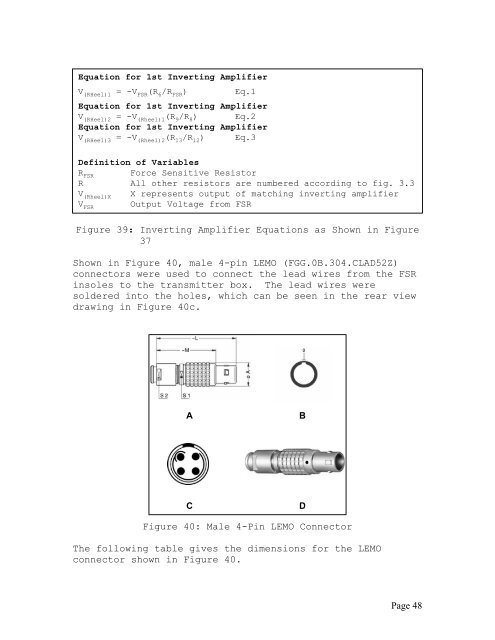
Shown in Figure 40, male 4-pin LEMO (FGG.0B.304.CLAD52Z)<br />
connectors were used to connect the lead wires from the FSR<br />
insoles to the transmitter box. The lead wires were<br />
soldered into the holes, which can be seen in the rear view<br />
drawing in Figure 40c.<br />
A<br />
B<br />
C<br />
D<br />
Figure 40: Male 4-Pin LEMO Connector<br />
The following table gives the dimensions for the LEMO<br />
connector shown in Figure 40.<br />
Page 48