Biomechanics Gait Analysis Lab - Biomedical Engineering ...
Biomechanics Gait Analysis Lab - Biomedical Engineering ...
Biomechanics Gait Analysis Lab - Biomedical Engineering ...

You also want an ePaper? Increase the reach of your titles
YUMPU automatically turns print PDFs into web optimized ePapers that Google loves.
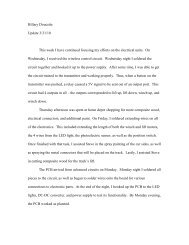
A<br />
B<br />
C<br />
D<br />
Figure 45: Male LEMO Connector<br />
The following table gives the dimensions for the LEMO<br />
connector shown in Figure 45.<br />
Metric A L M S1 S2<br />
mm. 9.5 35.0 25.0 8.0 7.0<br />
in. 0.37 1.38 0.98 0.31 0.28<br />
Table 3: Measurements for Figure 45A<br />
The female LEMO connector was soldered to the printed<br />
circuited board in the transmitter box and is shown in<br />
Figure 46. The layout for the lead input is shown in<br />
Figure 47, which shows the sections of the foot coming into<br />
each pin as well as the input voltage.<br />
A<br />
B<br />
Figure 46: Female LEMO Connector<br />
Page 53